Page 9Fiberlink® 3355 Series User’s Manual
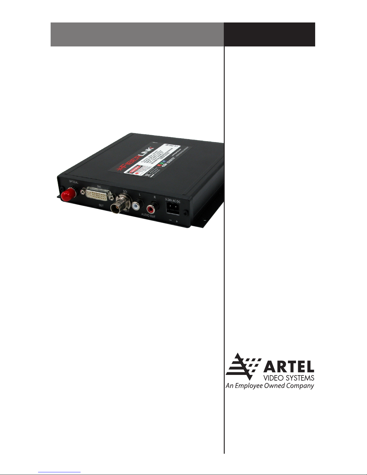
Fiberlink® 3355 Series
Operating Pointers
Remember to check attenuation of the ber optic cable. The system will only operate
properly if these specications fall within the range of the system’s loss budget.
Note: If no signal is applied to the 3355 Transmitter, no optical power will be present on the
3355 Transmitter’s output.
Troubleshooting
Multimode ber optic cable contains an optical ber with a light carrying “core” that is
only .0025 inches (62.5 microns) in diameter. Single mode ber optic cable has an even
smaller “core,”only .00032 to .0004 inches (8-10 microns). This is smaller than a human hair!
Therefore, any minute particles of dirt or dust can easily block the ber from accepting or
radiating light. To prevent this from happening, always use the provided dust caps when
ever optical connectors are exposed to air. It is also a good idea to gently clean the tip of an
optical connector with a lint-free cloth moistened with alcohol whenever dust is suspected.
The status of the LEDs should provide the rst clue as to the origin of any operational
failure. If these are o, it usually means that the ber is broken or has too much attenuation.
Next, be certain that the input and output signal connections are correct.
An optical power meter, such as the Fiberlink® 6615, a visible light source, such as the
Fiberlink® 6610, and a Three Wavelength Light Source, such as the Fiberlink® 6620, can
greatly assist and expedite troubleshooting of ber optic transmission systems and are
recommended tools all installers should have available.
Finally, although multimode and single mode devices may look the same, they will not
operate properly together. Using the wrong device or ber can easily add more attenuation
than specied, resulting in poor overall performance. It should be noted that some of our
ber optic products support both single mode and multimode ber in the same unit.
If, after reviewing the above possibilities, the system is still not operating, please contact
the Customer Service Department for further assistance. If you suspect your problem is
caused by the optics or the ber optic cable, and you have an optical power meter, please
take the appropriate measurements prior to contacting support.
Operating Pointers | Troubleshooting