ARVEN OP Series User manual

SUBMERSIBLE MOTOR OP 4”
OPERATING INSTRUCTION

CONTENTS
1.00 Introduction
1.01 Warranty
1.02 Description of motor
1.03 Trasport and installation
1.04 Thechnical particulars
,GHQWLÀFDWLRQSODWH
1.06 Generaly safety precatuions
1.07 Operating conditions
2.00 Installation
2.01 Start-up
3.00 Maintenance and service
4.00 Spare parts
5.00 Descriptions of symbol
1.00 INTRODUCTION
This brochure gives important information con-
cerning the installation,use and maintenance
of the motors. The contents of this brochure
refer to the standard product, and presented
in the sales documentation. Please refer to the
sales contract for the futures of variants and
special version. Always specify the exact type
of motor and code when requesting our Sales
and Service Department for technical informa-
tion spare parts. For any instruction,situations
and event not covered in this brochure or in
the sales documentation, please conctact
the nearest Technical Assistance Center.
Read this manual carefully before installing and
using the product.
The manufacturer shall not be held directly or
indirectly liable for any negligence or failure
to observe the instructions given in this bro-
chure, nor for any damage caused by faulty
installation and/or improper use of the motor.
At the time of purchase, check that the mo-
tor is intact and complete. Any complaints
shall have to be presented in writing within
seven (7) days of receving the motor.
1.01 WARRANTY
The manufacturer guarantees its products for
a period of twelve (12) months from the date
of purchase. This warranty is onlyexpressed
in the repair or replacement free of charge of
those parts that after careful examination by
the manufacturer turn out to be defective. War-
ranty excluding all liability for direct or indirect
damage, is considered to be restricted to ma-
terial defects inly (excluding electrical parts)
and ceases to have effect if the parts returned
anyhow turn out to have been dismantled.
tampered with, or repaired outside the fac-
tory. Returned equipment, even if in warran-
ty, shall have to be shipped with freight paid.
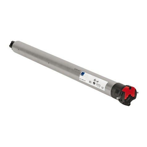
1.02 DESCRIPTION OF MOTOR (Fig.1)
1) Electric cable
2) Double ends studs, washer and nuts
,GHQWLÀFDWLRQVSODWH
The 4OS range comprises a number of 4”
submersible motors with stator and rotor in coo-
OLQJÀOOLQJÁXLGVXLWDEOHIRUXVHZLWKIRRGVWXIIV7KH
ÁDQJHFRQQHFWLRQVL]HPHHWV1(0$VWDQGDUGV
Each motor includes a cable with removable
connector.
1.03 TRASPORT AND INSTALLATION
The motor is supplied completely with a power
supply cable, in sturdy cardboard boxes suitable
for transportation and storage. It is advisable, in
thecaseofstorage,nottoexceedastackof4units.
Before installation, carefully read this bro-
chure and especially the safetyprecau-
tions described in paragraph 1.06. Pay at-
tention to the danger sign marked in this
brochure wich highlights a potential danger.

3
1.04 TECHNICAL PARTICULARS
MOTOR
TYPE
POWER H
mm
WEIGHT
Kg
kW Hp
OPM00750 0.55 0.75 381.5 8.5
OPT00750 386.5 8
OPM01000 0.75 1.0 401.5 9.4
OPT01000 406.5 9
OPM01500 1.1 1.5 432.5 10.7
OPT01500 442.5 10.4
OPM02000 1.5 2.0 472.5 12.6
OPT02000 482.5 12.1
OPM03000 2.2 3.0 585 17.3
OPT03000 560 16.9
OPT04000 3.0 4.0 635 20
OPT05500 4.0 5.5 684 22.3
OPT07500 5.5 7.5 804 27.9
OPT10000 7.5 10 919 33.6

4
1.05 IDENTIFICATION PLATE
1 Type of motor
2 Manufacturing date
3 Rated voltage
4 Protection class
5 Rated power in kW
6 Rated power in Hp
7 Frequuncy
8 Rated current
9 Power factor
10 Phase
11 Rated speed
12 Starter capacitor capacity
13 Capacitor voltage
14 Maximum ambient temperature
15 Class of insulation
16 The weight of the motor
17 Code
18 Maximum thrust load
19 Service factor
20 Symbol RAEE
1.06 GENERAL SAFETY PRECAUTIONS
When using electrical equipement, it is ne-
cessary to take the appropriate safety pre-
JH\[PVUZ [V YLK\JL [OL YPZR VM ÄYL LSLJ[YPJHS
shock, and injury to person. Therefore, before
using the equipement, carefully read and me-
morize the following safety instructions. After
reading, keep this brochure with care. The ma-
nufacturer shall not be heald liable for any non-
observance of the safety and accident-preven-
tion instructions described in this brochure.
- Keep the work area clean and tidy. Untidy areas
and environments make accidents more likely.
- Before starting work, become familar with the
control devices and their functions.
- Do not subject the equipment to work it could
not reasonably support.
- Operate only with good lighting, in a safe po-
sition free from hindrances.
- When handling the motor use suitable lifting.
- Equipment in conformity with the safety regu-
lations, and wear safety shoes and gloves.
- Never handle the equipement by pulling in its
power cable.
- Use only cables of allowed lenght, marked
and with suitable cross-sections.
- Protect the cable from high temperature, lubri-
ÄJHU[ZHUKZOHYWJVYULYZ
- During the installation operations, pay atten-
tion to hanging loads and follow the correspon-
ding safety instructions.
- Make the control panel and the electrical sy-
stem in accordance with current regulations.
- It is essential to use skilled personnnel since
motor are machines that due to their type of in-
stallations and starting to require precise tech-
nical knowledge.
1.07 OPERATING CONDITIONS
-Liquids in wich the motor can operate
This motor can be used in cold water. Do not
use this motor with corrosive or explosive li-
quids, or particularly dirty or hard water (impuri-
ties may deposit on the outer casing).
-Water temperature
Minimum water temperature is 0°C
Maximum water temperature is +35°C as long
HZ[OL ÅV^YH[LVM [OL^H[LY HYV\UK[OLTV[VY
does not fall below 0.16m/s

5
-Cooling the motor
To ensure the motor is correctly cooled, make
sure the plowrate of the water around the outer
casing is at least 0.16m/s when positioning the
motor in wells or tanks.
-Installation position
All the motors in the range can be installed
vertically.
Motors up to 2.2 kW power can be installed
horizontally.
-Depth of immersion
The maximum depth of immersion for all motors
is 150m.
-Power supply requirements
Make sure the supply voltage and frequency
match yhose indicated on the rating plate of the
motor.
The motors can generally work at the following
supply voltage tolerances.
f UN
Hz ~ V ± %
50 1 220V ± 10%
50 3 220V ± 10%
50 3 380V ± 10%
-Number of starts per hour
To get the best operation and longest service
life out of your motor and pump, the maximum
number of starting times is not more than 30
times.
-Compatible pumps
Make sure the motor is compatible with the
pump.
Incompatible combinations may cause pro-
blems.
In particular, before coupling the motor to the
pump check that:
-the power of the pump to couple to the motor
is less than or equal to that of the motor.
- the supply voltage and frequency match those
PUKPJH[LKVU[OLPKLU[PÄJH[PVUWSH[LVM[OLTV-
tor.
-the motor and pump shafts turn freely.
-Motor powered by a frequency converter
Only specially ordered motors can be powered
with a frequency converter.
If the motor is combined with a frequency con-
verter, downgrade power by 10% and make
sure never exceed the rated input frequency of
the motor.
To ensure the motor is properly cooled, the mini-
T\T^H[LYÅV^YH[LH[[OLTPUPT\TMYLX\LUJ`
VM\ZLT\Z[LX\HS[V[OLTPUPT\TÅV^YH[LPUKP-
cated in the previous points.
2.00 INSTALLATION
Installation must be done by competent and
authorized operators.
During installation,apply all the safety pro-
visions issued by the competent bodies in
the country of use and dictated by common
sense.
Before installing the motor, read this instruc-
tions manual and the one supplied the pump
or electric pump to wich the motor will be cou-
pled. Keep both manuals with care.
Use suitable equipment and protective devices.
-Selecting the electrical panel
Motors must be suitably protected against
overloads and short circuits.
The following starting systems can be used:
direct, impedance, autotransformer, soft-start.
Make sure the panel power ratings match those
of the pump. Incompatible combinations may
cause faults and fail to fully protect the motor.
Before installing, carefully read the instructions
supplied with the electrical panel.

6
- Pump connections
Before connecting the motor to the pump, read
this instructions manual and the one supplied
with the pump or electric pump to wich the mo-
tor will be coupled.
Keep both manuals with care.
-Installing the motor in a well or tank
Follow the instructions in the pump or electric
pump brochure.
When installing the electric pump vertically,
make sure the motor does not rest on the bot-
tom of the well ot tank.
When installing the electric pump horizontally,
make sure the motore does not rest on the bot-
tom of the tank.
2.01 START-UP
Follow the instructions in the pump or electric
pump manual
-Electrical connections to the electric pump
Electrical connections may only be performed
I`HX\HSPÄLKPUZ[HSSLY PUJVTWSPHUJL^P[OJ\Y-
rent regulations.
Make sure that the supply voltage and fre-
quency are compatible with the electrical panel.
The relative information is shown on the motor
PKLU[PÄJH[PVUWSH[LHUKPU[OLKVJ\TLU[ZZ\W-
plied with the panel. Provide suitable short cir-
cuit protection on the supply line.
Before proceeding, make sure that all the con-
nections (even if they are potential-free9 are
voltage-free.
UnlesZV[OLY^PZLZWLJPÄLKPUSVJHSI`SH^Z[OL
Z\WWS`SPULT\Z[ILÄ[[LK^P[O!
- a short circuit protection device.
- a high sensitivity residual current circuit brea-
ker (30mA) for addictional protection from elec-
[YVJ\[PVUPUJHZLVMPULMÄJPLU[NYV\UKPUN
- a general switch with a contact aperture of at
least 3 millimiters.
Ground the system in compliance with current
regulations.
Single-phase version
Connect the electric pump to a supply line via
a suitable electrical control panel containing the
overload protection and the capacitor.
Refer to the wiring KPHNYHTPUÄN\YLHUK[OL
documentation supplied with the electrical pa-
nel.
Refer to the motor rating plate for the capacity
of capacitor.
Install the electrical panel in a sheltred area.
Figure 2: Single-phase wiring diagram
Three-phase version
Connect the electrical pump to a supply line via
a suitable electrical control panel.
Install the electrical panel in a sheltered area.
Refer to the documentation supplied with the
electrical panel.
For connections to any external control follow
the instructions supplied with these devices.

7
3.00 MAINTENANCE AND SERVICE
Before proceeding, always make sure the motor
is disconnected from the supply line.
Maintance operations may only be performed
I` L_WLY[Z HUK X\HSPÄLK WLVWSL <ZL Z\P[HISL
equipment and protective devices. Observe all
accident prevention regulations.
Do not attempt to disconnect the connector
from the motor hand cable.
This may only be done by authorised personnel.
Only use original spare parts to replace faulty
components.
The motor does not require any scheduled rou-
tine maintenance.
Users wishing to prepare a maintenance sche-
dule should bear in mind that maintenance
cycle depends on the conditions of use.
For any requirements, please contact our Sales
and Service Department.
4.00 SPARE PARTS
Always specify the exact type of motor and
code when requesting our Sales and Assistan-
ce Service for technical information or spare
parts.
Only use spare parts to replace faulty compo-
nents. Unsuitable spare parts may cause the
product to work incorrectly and cause hazards
for people and property.
For further information, please contact our Sa-
les and Service Department.
5.00 DESCRIPTIONS OF SYMBOL
Read this brochure carefully
before proceeding
Electric shock failure to observe
this warning may result in the
electric shock
Warning sign indicates a potential
hazard

Arven S.r.l.
Via Artigiani n°10
25030 Maclodio - Brescia Italy
Tel. +39.030.9973973
Fax +39.030.9973975
www.Arven.it
0940.ARV0005.00
Ed. 04/2019_00
This manual suits for next models
14
Table of contents
