AS MOTOR AS 730 EcoBrush User manual

AS-Motor Germany GmbH & Co. KG
Ellwanger Straße 15 D-74424 Bühlertann
Internet: www.as-motor.de
E09800, E09810, E09875
Owners Manual Power Sweeper
Copyright © 2011 by AS-Motor Germany GmbH & Co. KG, Bühlertann Reproduction not permitted, neither in part nor in full. KR-332-025AB 10/2012-1
AS 730 EcoBrush/AS 830 EcoBrush
AS 830 H EcoBrush
EN- Translation of the Original Operating Instructions

Trademark
All trademarks, registered trademarks, trade names and brand names are property of their respective owners
and are acknowledged by us.
Shown drawings and illustrations may differ from the original.

1
Inhaltsverzeichnis
1 Operating and assembly instructions ........................................................................................................................... 2
1.1 General ..................................................................................................................................................................... 2
1.2 Warnings and symbols .............................................................................................................................................. 3
2 Fundamental safety instructions .................................................................................................................................. 4
2.1 Designated use of the machine ................................................................................................................................. 4
2.2 Organizational measures .......................................................................................................................................... 4
2.3 Selection and qualication of personnel - Basic responsibilities ............................................................................. 5
3 Condition on delivery, included in delivery ................................................................................................................ 5
4 Machine illustrations with danger zone, component description, safety label location and markings ................ 6
5 Assembly ......................................................................................................................................................................... 7
6 Commissioning ............................................................................................................................................................. 14
6.1 Fundamental safety instructions for standard operation ......................................................................................... 14
6.2 Steering height adjustment .................................................................................................................................... 15
6.3 Brush pressure ....................................................................................................................................................... 16
6.4 Adjusting the ejection direction ............................................................................................................................... 17
6.5 Swept material container (accessory) .................................................................................................................... 18
6.6 Stone impact protection cover (accessory) ............................................................................................................ 19
6.7 Plough blade (accessory) ........................................................................................................................................ 20
6.8 Snow chains (accessory) ........................................................................................................................................ 21
6.9 Movement drive and brush drive ........................................................................................................................... 22
6.10 Starting/switching off the motor (brief instructions) .......................................................................................... 23
7 Service and maintenance ............................................................................................................................................. 24
7.1 Fundamental safety instructions ............................................................................................................................. 24
7.2 Filling with fuel ..................................................................................................................................................... 25
7.3 Checking the oil ..................................................................................................................................................... 26
7.4 Replacing the brushes ............................................................................................................................................. 27
7.5 Cleaning the device ............................................................................................................................................... 28
7.6 Adjusting orresetting the Bowden cables ............................................................................................................... 29
7.7 Checking and correcting tyre pressure .................................................................................................................. 30
7.8 Freewheel lubricate only tk18 ............................................................................................................................. 30
7.9 Cleaning the air lter ............................................................................................................................................. 32
7.10 Storage .................................................................................................................................................................. 32
7.11 Maintenance plan ............................................................................................................................................... 32
8 Troubleshooting and fault elimination ....................................................................................................................... 33
9 Transport ...................................................................................................................................................................... 35
10 Specication ................................................................................................................................................................ 36
10.1 Specication AS730 ................................................................................................................................................. 36
10.2 Specication AS830 ................................................................................................................................................. 37

2
1.1 General
Operating and assembly instructions
1 Operating and assembly instructions
These operating and assembly instructions are desi-
gned to familiarize the user with the machine and its
designated use.
The operating and assembly instructions contain im-
portant information on how to operate the machine
safely, properly and most efciently. Observing these
instructions helps to avoid danger, to reduce repair
costs and downtimes and to increase the reliability and
life of the machine.
The operating and assembly instructions must always
be available wherever the machine is in use.
These operating and assembly instructions must be
read and applied by any person in charge of carrying
out work with and on the machine, such as
- operation including setting up, troubleshooting
in the course of work, evacuation of production waste,
care and disposal of fuels and consumables
-maintenance (servicing, inspection, repair)
and/or
-transport.
In addition to the operating and assembly instructions
and to the mandatory rules and regulations for acci-
dent prevention and environmental protection in the
country and place of use of the machine, the generally
recognized technical rules for safe and proper working
must also be observed.

Read the instructions for use
1.2 Warnings and symbols
WARNING!
indicates a potentially dangerous situation. Ignoring this instruction may lead to serious or
fatal injury.
CAUTION!
indicates a potentially dangerous situation. Ignoring this instruction may lead to minor injury.
IMPORTANT!
indicates tips for use and other useful information.
3
Operating and assembly instructions
Use a workbench
Do not use tools
Symbol
Type
Quantity
2x M8x20
DANGER!
indicates immediate danger. Ignoring this instruction poses a risk of serious or fatal injury.
Symbol
Bolt
Washer
Nut
Open-end spanner
Nut driver
Screwdriver
Phillips screwdriver
Type
Example:
M8 x 16
8,1 - 58 - 5
M8 (S)
8
PZ 2
PH 2
Description
M = Metric
S = Diameter in mm
16 = Length in mm
8,1 = Inner diameter
58 = Outer diameter
5 = Material thickness in
mm
M = Metric
8 = Inner diameter
(S) = Lock nut
8 = Size in mm
PZ 2 = Pozidrive in mm
PH2 = Phillips size 2

Fundamental safety instructions
4
2.2 Organizational measures
The operating and assembly instructions must always
be at hand at the place of use of the machine.
In addition to the operating and assembly instructions,
observe and instruct the user in all other generally ap-
plicable legal and other mandatory regulations relevant
to accident prevention and environmental protection.
These compulsory regulations may also deal with
the handling of hazardous substances, issuing and/or
wearing of personal protective equipment, or trafc
regulations.
must be supplemented by instructions covering the
duties involved in supervising and notifying special
organizational features, such as job organization,
working sequences or the personnel entrusted with
the work.
Personnel entrusted with work on the machine must
have read the operating instructions and in particular
the chapter on safety before beginning work. Reading
the instructions after work has begun is too late. This
applies especially to persons working only occasionally
on the machine, e.g. during setting up or maintenance.
Check - at least from time to time - whether the per-
sonnel is carrying out the work in compliance with the
operating instructions and paying attention to risks
and safety factors.
For reasons of safety, long hair must be tied back or
otherwise secured, garments must be close-tting and
no jewellery may be worn, including rings. Injury may
result from being caught up in the machinery or from
rings catching on moving parts.
Use protective equipment wherever required by the
circumstances or by law.
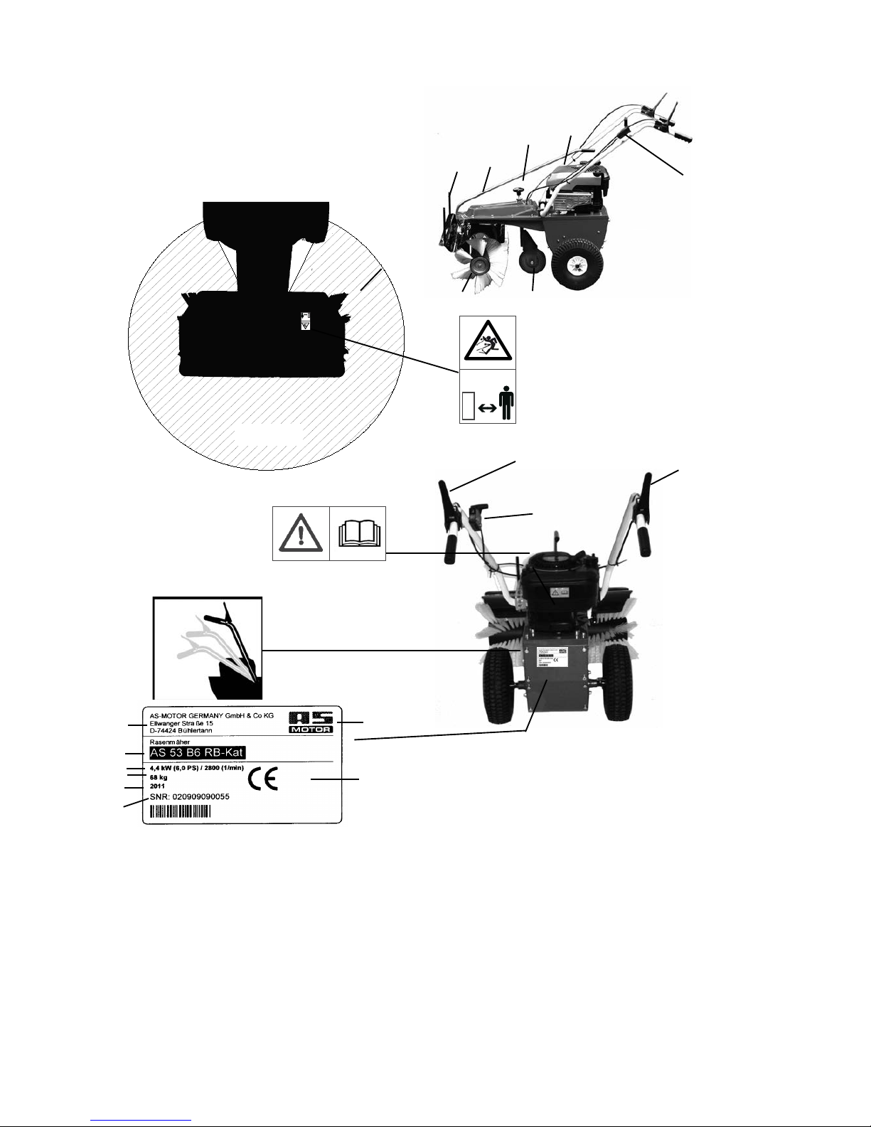
Observe all safety instructions and warnings attached
to the machine.
Make sure that safety instructions and warnings
attached to the machine are always complete and
perfectly legible.
In the event of safety-relevant modications or changes
in the behaviour of the machine during operation, stop
the machine immediately and report the malfunction
to the relevant specialized dealer.
Never make any modifications, additions or con-
versions which might affect safety without the
manufacturer’s approval. This also applies to the in-
stallation and adjustment of safety devices and valves
as well as to welding work on load-bearing elements.
Only use original spare parts from the manufacturer.
These meet technical requirements and include war-
ranty and guarantee claims. Adhere to prescribed inter-
vals or those specied in the operating and assembly
instructions for routine checks and inspections.
For the execution of maintenance work, tools and
workshop equipment adapted to the task on hand are
absolutely indispensable.
The personnel must be familiar with the location and
operation of re extinguishers.
Observe all re-warning and re-ghting procedures.
2.1 Designated use of the machine
The product has been built in accordance with state-
of-the-art standards and the recognized safety rules.
Nevertheless, its use may constitute a risk to life and
limb to the user or third parties, or cause damage to
the product and other material property.
The product must only be assembled in technically
perfect condition in accordance with its designated
use and the instructions set out in the operating and as-
sembly manual, and only by safety-conscious persons
who are fully aware of the risks involved in operating
the machine. Any functional disorders, especially
those affecting safety, should therefore be rectied
immediately.
The product is designed exclusively for tting to
machines approved by the manufacturer and for ac-
cessories approved by the manufacturer. Using the
machine for purposes other than those mentioned
above is considered contrary to its designated use. The
manufacturer/supplier cannot be held liable for any da-
mage resulting from such use. The risk of such misuse
lies entirely with the user. The machine is exclusively
intended for the private use.
Operating the machine within the limits of its designa-
ted use also involves observing the instructions set out
in the operating and assembly manual and complying
with the inspection and maintenance directives.
2 Fundamental safety instructions

3) Please dispose of the packaging material as recy-
cling waste.
4) The machine is delivered in a folding carton:
1 brushing machine
1 extra package with
- operating manual
- motor operating manual
Accessories (to be ordered separately)
- swept material container
- plough blade
- stone impact protection cover
- snow chains
3 Condition on delivery, included in delivery
1) Checking the original packing (dirt collector
box)
2) Checking the original packing (tk520 sweeper
attachment)
5
Fundamental safety instructions
2.3 Selection and qualication of personnel - Basic responsibilities
Any work on and with the product must be executed by
reliable personnel only. Statutory minimum age limits
must be observed.
Employ only trained or instructed staff and set out
clearly the individual responsibilities of the personnel
for operation, set-up, maintenance and repair.
Make sure that only authorized personnel works on or
with the product.
Do not allow persons to be trained or instructed or
persons taking part in a general training course to work
on or with the product without being permanently
supervised by an experienced person.
Work on the electrical system and equipment of the
product should only be carried out by a skilled elec-
trician or by instructed persons under the supervision
and guidance of a skilled electrician and in accordance
with electrical engineering rules and regulations.
Work on chassis, brake and steering systems must
only be performed by skilled personnel that have been
specially trained for such work.
Work on the hydraulic system must only be carried out
by personnel with special knowledge and experience
of hydraulic equipment.

1
6
23
5
6
7
8
16 18
17
1. Danger zone
2. Swept material container retainer
3. Swivel lever for side adjustment of brushes
4. Brush height adjustment
5. Motor
6. Handlebar, height-adjustable
7. Support wheel
8. Brushes
9. Manufacturer‘s name
10. CE identication
11. Serial number
4
Carefully read
opeator’s manual
before handling the
machine. Observe
instructions and safety
rules when operating
Danger - ying objekts; keep safe di-
stance from the machine as long as the
engine is running.
Ø = 10 m
Machine illustrations with danger zone
4 Machine illustrations with danger zone, component description, safety label location and markings
12. Motor power
13. Motor manufacturer
14. Machine type
15. Manufacturer‘s address
16. Movement drive (forwards)
17. Throttle lever
18. Brush drive
19. Weight
20. Construction year
10
9
14
19
20
12
15
11

Assembly
7
5 Assembly
Delivery-condition.
Clamp with xing material to x the handlebar.
Put the clamp on the screw threads.
Clamp in correkt position.
Put the handlebar onto the clamp.

Assembly
8
Put the clamp on the screw threads.
Put the washer on the screw threads.
Tighten the locknut on the screw threads.
SW 10
4 x M6
6,4-18-1,5
Choose the steering height.
M8 x 24
Star grasp screw in. The steering wheel must t laterally.

Put the wheel onto the axle.
CAUTION!
The valve is outside.
Tighten the wheel with washer and a hinged pin.
To the better montage of the support wheel, the machine
should be back-tilted.
CAUTION!
It tilts machine only if no strength and lubri-
cants were yet lled.
Assembly
9
Fortify the Clutch cable with cable-straps.
Nuts with a ring thin spanner easily attract. The steering
wheel must be rmly installed. The steering wheel must be
able itself to turn in the clips.
CAUTION!
The steering wheel must be rmly installed. If
the star grasp is not screwed in, the steering
wheel in the deepest position may not tilt
automatically downward.

Assembly
10
Support wheel with xing material
Push the sleeve through the wheel.
Push the hex bolt through.
Put on the washer.
M 12 x 70
13-24-2
Positioning the support wheel

Brushes with extra components.
Push the nut onto the axle.
Push the washer and cap onto the axle and then tighten
the nuts.
M10
M10
14-58-5
Assembly
11
Tighten the nut. Hold the bolt head with a ring spanner and
tighten the nut with a second ring spanner
M12
2 x SW 19
Tighten using two ring spanner.
2 x SW 17

Assembly
12
Push the brush onto the axle.
Push the brush with the axle through the opening in the
gearbox.
Assembly information:
The brush recesses should be placed against the gear spigot.
Push the other brush onto the axle
Push the washer and cap onto the axle.
14-58-5

Assembly
13
Tighten the locknut.
M10
Tighten using two ring spanner. (You will have to hold the
nut at the other end of the axle with another ring spanner).
2 x SW 17

14
Commissioning
6.1 Fundamental safety instructions for standard operation
6 Commissioning
Avoid any operational mode that may be prejudicial
to safety.
Before beginning work, familiarize yourself with the
location of installation and circumstances of the site.
This includes obstacles in the working and travelling
area, the earth load capacity and any barriers separating
the location of installation from public roads.
Take the necessary precautions to ensure that the
machine is used only when in a safe and reliable state.
Operate the machine only if all protective and safety-
oriented devices, such as removable safety devices,
sound-proong elements and exhausters, are in place
and fully functional.
Check the machine for obvious damage and faults each
time you use it. Report any changes (incl. changes in
the machine’s working behaviour) to a specialized
dealer. If necessary, stop the machine immediately
and lock it.
In the event of malfunctions, stop the machine im-
mediately and lock it. Have any defects rectified
immediately.
Start the machine from the driver’s seat only.
During start-up and shut-down procedures always
watch the indicators in accordance with the operating
and assembly instructions.
Before starting up or setting the machine in motion,
make sure that nobody is at risk.
Before starting work or travelling with the machine,
check that the braking, steering, signalling and lighting
systems are fully functional.
Before setting the machine in motion always check that
the accessories have been safely stowed away.
When driving on public roads, pathways or open
spaces, observe the applicable trafc regulations and,
if appropriate, make the necessary adjustments to the
machine to ensure it meets the legal requirements.
In conditions of poor visibility and after dark always
ensure that there is sufcient lighting.
Always keep at a distance from the edges of building
pits and slopes.
Avoid any operation that might be a risk to machine
stability.
Never travel across slopes; always keep the working
equipment and the load close to the ground, especially
when travelling downhill.
On sloping terrain always adapt your travelling speed
to the prevailing ground conditions. Never change to
a lower gear on a slope but always before reaching it.
Before leaving the driver’s seat always secure the
machine against inadvertent movement and unautho-
rized use.

1) There are three settings for adjusting the handlebar
height.
6.2 Steering height adjustment
2) Choose the righthandlebar height.
CAUTION!
Switch off motor. Secure the machine against unintentional starting.
Commissioning
15
4) Heed the three settings for adjusting the handlebar
height.
5) You can fold the handlebar right to the front before
putting the machine away or storing it to save space.
3) Fix the handlebar with the stargripp.
CAUTION!
Make sure that steering control is
safely locked.

6.3 Brush pressure
Commissioning
3) Turn clockwise (+) : raise brush
Turn anticlockwise (-) : lower brush
1) You can adjust the brush pressure in ne stages.
For this reason the support wheel can be adjusted
for height.
2) The adjustment knob can be found above the sup-
port wheel.
IMPORTANT!
If the brushes are heavily worn, or if you are brushing cobblestones, lower the brush one more turn.
Please note: if the brush pressure is too heavy, the cleaning effect is decreased because the brush
hairs are bent too much.
If you do not intend to use the brushing machine for a long period, please release the pressure on
the brush. Raise brush
4) Lower the brush until it just touches the oor. Then
turn two rotations anticlockwise in the direction of
the arrow (-).
16
5) Tighten the support wheel

Commissioning
6.4 Adjusting the ejection direction
1) There are ve different settings available for adju-
sting the ejection direction.
Here: ejection direction forwards. This direction
means that the swept material will heap up in front
of the brushes. You should give preference to side-
ways facing brush settings.
3) The swept material will now be placed or
brushed to one side. This setting is particularly
advantageous in snow for clearing footpaths.
Here: ejection direction to the left.
2) Lift the pivoted lever out of the front toothing so
that the lever is disengaged.Turn the brush in the
required direction and allow the lever to engage
securely again.
Here: ejection direction to the right.
4) If you are using a swept material container, we
recommend a sideways setting. This will enable
you to work right up to a border (such as a house
wall or kerbstone) even with the container attached.
17
5) If you use a plough blade, you have to chose a side-
ways setting.
Here: ejection direction to the right.
DANGER!
Hurling parts at brush-rotation. Make completely sure that there are no persons or objects within
the danger zone, otherwise injuries and damage to materials could result. Secure the machine
against unintentional starting.
6) With the reversing with the sweeper, the brushes
must always be brought into the straight position.

6.5 Swept material container (accessory)
1) The swept material container (accessory) includes:
1 Swept material container
2 Operating manual
3 Washer
3) Push the swept material container over the receiving
bar.
1
2
Commissioning
18
4) When doing so, make sure that the upper rubber lip of the container is located below the sweeping brush cover.
WARNING!
Switch off motor. Secure the machine against unintentional starting.
3
2) Put the washers onto the receiving bars.
This manual suits for next models
2
Table of contents