ASAHI PENTAX AL-M2 Series User manual

PENTAX
AUTOMATIC
LEVEL
/1L-A12
SERIES
gL-Aia
•
AL-MSc
•
/IL-AIgs
INSTRUCTION
MANUAL

(For
proper
operation
of
instrument)
Pentax
automatic
level
AL-M2
series
consist
of
a
variety
of
instruments
in
order
to
comply
with
a
wide
range
of
surveying
from
second
or
third
order
leveling
surveying
to
civil
engineering
requiring
high
accuracy.
Our
surveying
instruments
are
precise
in
function
and
precision
made.
Survey¬
ing
instruments
do
not
either
work
well
nor
become
of
value
unless
they
are
carefully
handled
and
operated.
For
the
instrument
to
work
efficiently
and
be
useful
for
long
time,
read
through
this
instruction
book.
Storage
This
instrument
should
be
stored
in
a
dry,
dust-proof
room,
which
does
not
have
a
big
temperature
range.
When
the
instrument
is
stored
for
a
long
time,
it
must
occasionally
be
taken
out
of
the
case
and
air
circulated
freely
around
the
instrument.
When
storage
or
transportation
temperature
is
extremely
different
from
the
working
temperature,
the
instrument
must
be
allowed
to
come
to
the
ambient
temperature.
Exposure
time
required
is
approximately
one
minute
per
one
degree
temperature
difference.
Transport
For
shipment,
the
instrument
should
be
packed
with
cushioning
material
with
reasonable
thickness
on
all
sides.
Insurance
coverage
is
recommended.
Vehicle
transportation
does
not
require
packing
but
movement
should
be
restricted
by
securing
it.
When
heavy
vibration
or
rough
travel
is
encountered,
it
is
recommended
that
the
instrument
be
secured
in
a
padded
box.
Checking
Before
measurement,
an
instrument
should
be
examined
according
to
this
instruction
book.
If
necessary,
the
instrument
should
be
adjusted.
Even
a
new
instrument
or
completely
repaired
instrument
needs
to
be
checked.
This
proce¬
dure
is
also
recommended
during
long
intervals
of
non-use
or
after
long
journey.
At
least
once
per
year,
or
more
often,
it
is
recommended
that
the
instrument
should
be
checked
by
a
qualified
Pentax
dealer.

Unpacking
When
removing
an
instrument
from
its
carrying
case,
pay
attention
to
how
it
is
positioned
so
that
it
can
be
returned
properly.
Grasp
the
instrument
securely
when
removing
or
returning
it
from
or
to
the
case.
Setting
up
When
installing
or
removing
the
instrument
on
or
from
the
tripod,
the
instru¬
ment
should
be
securely
held
with
one
hand
while
the
other
hand
manipulates
tripod
center
screw.
The
instrument
should
never
be
left
on
the
tripod
without
being
fastened
down.
Failure
to
carry
out
these
instructions
can
result
in
a
bad
accident.
Careful
operation
and
handling
of
the
instrument
in
accordance
with
these
instructions
and
plain
common
sense
will
provide
long
and
useful
service.
-
2
-

Contents
1.
Features.4
2.
Description
.5
3.
Equipment.6
4.
Specifications
.7
5.
Operation
□
Preparation
for
surveying
1)
Setting
up
the
tripod
.8
2)
Setting
up
the
instrument.8
3)
Leveling
.9
□
Observation
1)
Reticle
collimation.9
2)
Sighting
.
10
3)
Reading
the
staff.
11
HI
Surveying
1)
Leveling
.
11
2)
Stadia
survey.
12
3)
Angle
measurement.
13
6.
Maintenance
and
packing
□
Maintenance.
14
□
Packing
.
14
7.
Precaution.
15
8.
Inspection
and
adjustment
□
Circular
level.
15
□
Leveling
line
of
sight.
16
9.
Optional
accessories
□
Electric
illumination
[EP].
18
□
Parallel
plate
micrometer
[SM3].
19
□
Diagonal
eyepiece
[SBL1]
.
21
-
3
-

1.
Features
■
Easy
to
operate
due
to
simple
design,
and
compact
and
light
construction,
■
The
telescope
is
of
dust
-
and
water
resistance,
enabling
use
of
the
instru¬
ment
in
the
rain
or
tunnel
with
humidity.
■
Minimum
focus
distance
is
extremely
short,
0.8m.
Anallactic
optics
of
the
telescope
makes
stadia
surveying
easy
as
the
stadia
constant
is
0.
■
With
special
alloy
ribbon
with
long-established
reputation,
a
newly
developed
automatic
compensator
having
magnet
damper
is
of
wire-
suspension
type
and
provides
extremely
stable
surveying
results
even
under
unfavorable
conditions
such
as
vibration,
■
Optical
collimator
provides
fast
and
accurate
sighting.
■
Concurved
foot
plate
fits
domed
head
tripod
as
well
as
flat-head
tripod.
■
Adjustable
reflecting
prism
permits
operator
to
observe
the
circular
level
without
changing
his
operating
position,
thus
enabling
easy
confirmation
of
leveling.
■
Clampless
horizontal
drive
screw
equipped
with
knobs
on
both
ends
pro¬
vides
endless
movement
of
the
telescope.
■
AL-M2C
with
a
horizontal
circle
permits
horizontal
angle
measurement
as
well
as
angle
setting.
■
AL-M2S
equipped
with
a
glass
circle
graduated
down
to
10'
or
10c
permits
angle
measurement
with
higher
accuracy.
Fine-coarse
focussing
screw
provides
fast
and
accurate
focussing.
■
Electric
illumination,
parallel
plate
micrometer
and
diagonal
eyepiece
are
available
as
optional
accessories.
-
4
-

2.
Description
Collimator
Circle
rotation
ring
Circle
reading
window
(For
AL-M2C,
AL-M2S
only)
(For
AL-M2C
only)
-
5
-

3.
Equipment
[T]
Standard
Equipment
Instrument.1
Carrying
case
.1
Objective
cap
.1
Sunshade
.
1
Plumb
bob
(AL-M2C,
M25
only)
.1
Screw
driver
.1
Adjusting
pins.2
Brush.1
Rain
cover
.1
Silicone
cloth.1
[2]
Optional
accessories
Tripod
(TS-3)
Parallel
plate
micrometer
(SM3)
Electric
illumination
(EP)
Diagonal
eyepiece
(SBL1)
6
-

4.
Specifications
AL-M2
AL-M2C
ALM2S
■
Telescope
(Internal
Anallactic
Optics)
Image
Erecting
Magnification
32
x
Objective
aperture
45mm
Resolving
power
2.5"
Field
of
View
2.3%
(2.3m
at
100m
or
2.3
feet
at
100
feet)
or
1
°2Q'
Minimum
focus
distance
0.8m
Stadia
ratio
1
:
100
Stadia
constant
0
■
Automatic
Compensator
Range
±12'
Setting
accuracy
±0.3"
Standard
deviation
1
km
double
run
levelling
±1.0mm
■
Circular
level
Sensitivity
872mm
■
Horizontal
Circle
—
metal
glass
Diameter
—
100mm
88mm
Graduation
—
1°
or
1G
10'
or
10C
Reading
method
—
Index
Index
Least
Reading
—
Tor
1G
10'or
10c
Estimation
Reading
—
0.1°
or
0.1G
V
or
1c
■
Tripod
attaching
screw
Thread
5/8"
x
11
■
Dimensions
&
Weight
Length
254mm
Width
140mm
Height
137mm
Weight
2.1
Kgs/4.6
lbs
2.3
Kgs/5.0
lbs
■
Case
350
(L)
x
210
(W)
x
200
(H)
mm,
2.5
Kgs/55
lbs
Tripod
TS-3
1-1.7m
Length,
4.5
Kgs/9.9
lbs
7
—

5.
Operation
[T]
Preparation
for
surveying
1)
Setting
up
the
tripod
©
Prepare
the
tripod
having
a
center
locking
screw
with
5/8"x11
thread.
©
Dig
the
legs
firmly
into
the
ground
and
adjust
the
tripod
to
the
height
suitable
for
observation
when
the
instrument
is
mounted.
©
For
angle
measurement,
set
the
tripod
so
that
the
center
of
the
tripod
head
is
positioned
right
above
the
ground
point.
2)
Setting
up
the
instrument
©
Mount
the
instrument
on
the
tripod
head
and
secure
it
using
a
center
lock
screw.
{Fig,
4)
©
Suspend
the
plumb
bob
from
the
hook,
adjusting
the
length
of
the
string,
(for
angle
measurement)
©
Loosing
the
center
lock
screw,
move
the
instrument
with
the
tips
of
fingers.
Tighten
it
as
a
tip
of
plumb
bob
coincides
with
the
ground
point
(for
angle
measurement)
-
8
-

3)
Leveling
(D
Place
the
telescope
in
parallel
to
the
line
connecting
two
optionally
selected
leveling
screws,
and
turn
them
to
move
the
bubble
of
the
circular
level
at
a
position
even
to
the
left
and
the
right.
(Fig.
A)
■
Turn
the
two
leveling
screws
in
opposite
directions.
©
Turning
a
remaining
leveling
screw,
shift
the
bubble
to
the
center.
(Fig.
B)
CD
Make
sure
that
the
bubble
stays
at
the
center
of
the
circle
even
after
turning
the
telescope
180°.
■
See
arrows
in
Fig.
A
and
B
for
the
relation
between
the
direction
of
leveling
screw
rotation
and
the
bubble
shifting
direction.
■
If
the
bubble
is
out
of
the
center
in
(5),
"adjustment
of
the
circular
level"
on
page
15
is
needed.
[
2
]
Observation
1)
Reticle
collimation
©
Remove
the
objective
cap.
If
necessary,
attach
the
sunshade.
©
Directing
the
telescope
to
the
bright
background,
rotate
the
eyepiece
coun¬
terclockwise
to
draw
out
the
eyepiece
ring.
©
While
looking
into
the
eyepiece,
rotate
it
clockwise
until
the
cross
hair
of
the
reticle
comes
to
its
extreme
sharpness.
■
It
is
advisable
to
relax
when
looking
into
the
eyepiece.
An
intense
look
at
the
reticle
may
tend
to
cause
parallax
or
eye
fatigue.
-
9
-

Cross
hairs
Fig.
6
Field
of
view
2)
Sighting
©
Sight
the
telescope
at
the
object
looking
through
the
collimator.
©
Looking
into
the
eyepiece,
rotate
the
focussing
knob
until
the
object
be¬
comes
dearly
visible.
Make
sure
that
the
relation
between
the
object
and
the
cross
hair
does
not
change
even
when
you
move
your
eye
up
or
down¬
ward.
(Fig.
7)
■
If
parallax
exists
in
®,
the
relation
between
the
object
and
the
cross
hair
may
change.
This
may
cause
surveying
error.
Fig.
7
-
1
0
-

3)
Reading
the
staff
How
to
read
the
graduation
on
the
staff.
Reading
value
2.195m
■
Reading
of
the
staff
should
be
done
at
the
center
of
the
cross
hair
on
the
reticle.
[
3
]
Surveying
1)
Leveling
•
How
to
get
the
difference
in
height
and
the
elevation
Difference
in
height
(Ah)
^
backsight
(b)
-
foresight
(f)
Elevation
at
point
B
(he)
=
Elevation
at
point
A
(hA)
+
Ah
S
(1):
Staff
(I)
S
(IT):
Staff
(II)
I:
Instrument
B.S:
Backsight
(Staff
reading
at
the
point
where
eleva¬
tion
is
specified.)
F.S:
Foresight
(Staff
reading
at
the
point
where
elevation
is
unspecified.)
hA
Fig.
9
Datum
level
i

I
Difference
in
height
(AH)
=
£Ah
■
Set
the
instrument
at
almost
middle
of
two
staffs.
■
When
reading
the
staff,
try
to
get
least
reading
by
tilting
the
staff
back
and
forth
slightly.
■
For
more
precise
surveying,
use
the
double
run
method.
2)
Stadia
survey
Distance
from
the
instrument
to
the
staff
can
be
measured
by
the
stadia
hairs
visible
within
the
field
of
view
of
the
telescope.
■
To
measure
the
distance
is
easy
as
stadia
constant
is
0.
S:
Horizontal
distance
f
:
Difference
in
reading
between
of
upper
and
of
lower
stadia
lines
S=100
t
(A)
Fig.
11
(B)
-
1
2
-
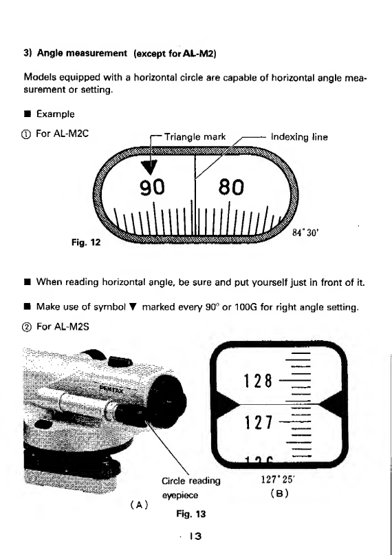
3)
Angle
measurement
(except
for
AL-M2)
Models
equipped
with
a
horizontal
circle
are
capable
of
horizontal
angle
mea¬
surement
or
setting.
■
Example
■
When
reading
horizontal
angle,
be
sure
and
put
yourself
just
in
front
of
it.
■
Make
use
of
symbol
T
marked
every
90°
or
100G
for
right
angle
setting.
©
For
AL-M2S

6.
Maintenance
and
packing
[T]
Maintenance
©
Clean
dust
or
water
from
the
instrument
and
then
put
it
back
to
the
case
after
using
it.
(2)
Brush
dust
off,
wipe
off
moisture
on
exposed
parts
with
a
soft
cloth.
<D
Wipe
off
the
moisture
on
the
surface
of
the
lenses
with
a
cotton
cloth,
using
light
pressure,
after
brushing
the
dust
off.
[
2
]
Packing
©
Gently
put
the
instrument
into
the
case,
facing
focussing
knob
toward
you.
©
Close
the
case
and
secure
the
latch.

7.
Precaution
O
Attach
the
sunshade
to
the
telescope
to
avoid
the
direct
sunlight
when
high
precise
survey
needed.
<0
Operate
the
instrument
carefully.
Do
not
apply
excessive
pressure
to
it.
O
Store
the
instrument
in
a
dry
place,
removing
dust
or
moisture
after
use
of
it.
O
Be
careful
not
to
subject
the
instrument
to
impact
or
vibration
during
trans¬
port.
O
When
moisture
or
disorder
is
found
inside
the
lens,
contact
your
dealer,
do
not
attempt
to
dismantle
the
instrument
by
yourself.
<0
When
any
malfunction
due
to
falling
down
or
some
other
cause
is
recog¬
nized,
contact
your
dealer,
do
not
attempt
to
forcibly
dismantle
the
instru¬
ment
by
yourself.
O
Check
all
parts
of
the
tripod
are
firmly
secured.
8.
Inspection
and
adjustment
[7]
Circular
level
1)
Inspection
©
Setting
the
instrument
on
the
tripod,
level
it
so
that
the
bubble
of
circular
level
is
positioned
at
the
center
of
the
circle.
(Refer
to
P.9
"Leveling".)
©
Turn
the
telescope
180°.
©
No
further
adjustment
is
necessary
if
the
bubble
stays
at
the
center
of
the
circle.
2)
Adjustment
©
if
the
bubble
moves
out
of
the
center
in
the
circle,
turn
the
leveling
screw
to
shift
the
bubble
halfway
back
after
taking
off
the
reflecting
prism.
(Fig.
A)
©
Shift
the
bubble
remaining
halfway
to
the
center
by
turning
adjustment
screws.
(Fig.
B)
©
Turn
the
telescope
180°
to
check
to
see
if
the
bubble
stays
at
the
center
of
the
circle.
®
Repeat
again
from
©
should
the
bubble
move.
-
15

■
When
doing
adjustment,
finish
screws
being
firmly
tightened.
[
2
]
Leveling
line
of
sight
Target
plate
Approx.
2m
1)
Inspection
(T)
Prepare
two
same
target
plates.
Setting
up
the
instrument
midway
between
two
walls
at
a
distance
of
50
to
100
meters,
level
it.
(Fig.
16(A))
(2)
Sighting
both
walls
alternately*
adjust
the
target
plates
to
the
height
so
that
readings
of
the
target
plates
are
identical,
and
secure
them
in
position.
(5)
Move
the
instrument
to
a
position
approx.
2
meters
from
one
target
plate
and
level
it.
(Fig.
16(B))
®
Read
both
target
plates.
(
5
)
No
adjustment
is
necessary
if
readings
of
both
target
plates
are
identical.
16

2)
Adjustment
©
Sight
the
farthest
target
plate
through
the
telescope.
(
2
)
Remove
the
eyepiece
cover,
rotate
the
reticle
adjusting
screw
using
the
adjusting
pin
and
adjust
the
reading
to
be
identical
to
that
of
the
nearest
target
plate.
(D
After
checking
that
correct
adjustment
has
been
made,
mount
the
eyepiece
cover
back
in
place.
Adjustment
screws
17

9.
Optional
accessories
[7]
Electric
illumination
[EP]
Electric
illumination
permits
surveying
work
in
a
tunnel
or
any
dark
place
by
way
of
illuminating
the
reticle.
Light
source
.
Green
LED
Power
supply
...
Two
1.5V
dry
batteries
(SUM-3)
(p
It
can
be
mounted
in
the
same
way
that
a
sunshade
is
attached
to
the
tele¬
scope
objective.
(
2
)
Turn
the
switch
on
and
adjust
brightness
by
rotating
illuminator
knob
while
looking
into
the
telescope.
■
Remove
battery
when
device
will
not
be
used
for
an
extended
period
as
extended
storage
may
cause
damage
to
the
device
due
to
leakage
of
battery
acid.
-
Electric
illumination

\T}
Parallel
plate
micrometer
[SM3]
Parallel
plate
micrometer
is
used
for
leveling
or
civil
engineering
work
requiring
precise
accuracy.
With
a
bright
microscale
etched
on
optical
glass,
it
provides
reading
down
to
0.1mm.
■
Use
the
instrument
with
wedge
type
reticle
for
use
of
the
parallel
plate
mic¬
rometer.
■
Replacement
of
the
reticle
if
your
instrument
is
equipped
with
ordinary
reticle
should
be
made
at
your
dealer.
■
Use
second
order
staff
or
equivalent
to
it,
not
ordinary
one.
Operation
(T)
Mount
the
parallel
plate
micrometer
horizontally
on
the
object
and
counter¬
weight
on
the
eyepiece
of
the
telescope,
respectively
and
secure
both.
(Fig.
19)
(
2
)
Turning
the
micrometer
knob,
accurately
put
the
staff
graduation
between
the
wedge-shaped
lines,
(Fig.
20)
(5)
Read
the
staff
<A|
and
microscale
(B}
.
micrometer
Fig.
19
-
19-
This manual suits for next models
3
Table of contents


