Solutions for Fluid Technology
HBE GmbH
Hönnestraße 47 | 58809 Neuenrade | Germany
Phone +49 (0) 23 94 / 616-0
Fax +49 (0) 23 94 / 616-25
info@hbe-hydraulics.com
www.hbe-hydraulics.com
5.2 CHANGES OF COUPLING
DANGER!
A change at the coupling parts is only permitted
after having checked with the manufacturer.
For making the shaft bore by the user, please pay attenti-
on to the following items:
• The maximum admissible bore diameter d1 + d2 (see
Technical Data) must not be exceeded. In case of
disregard of these values, the coupling might break.
Flying fragments can cause serious personal injuries.
This concerns all materials.
• The predetermined planning and rotation accuracy of
the manufacturer must be adhered to.
• For making the finish bore, a careful alignment must be
made.
• For the axial safety device, please use a locking screw.
• If using a locking screw, following tightening torques
must be kept (see table):
5.3 MOUNTING
INDICATION!
Before mounting, we recommend to check the bores,
shaft, hub and feather key for accuracy.
A heating of the hubs to approx. 80°C eases the fitting
onto the shaft.
DANGER!
In order to avoid burnings by the contact with ted
hubs, please wear safety gloves.
CAUTION!
Please pay attention to the danger of ignition in
hazardous areas.
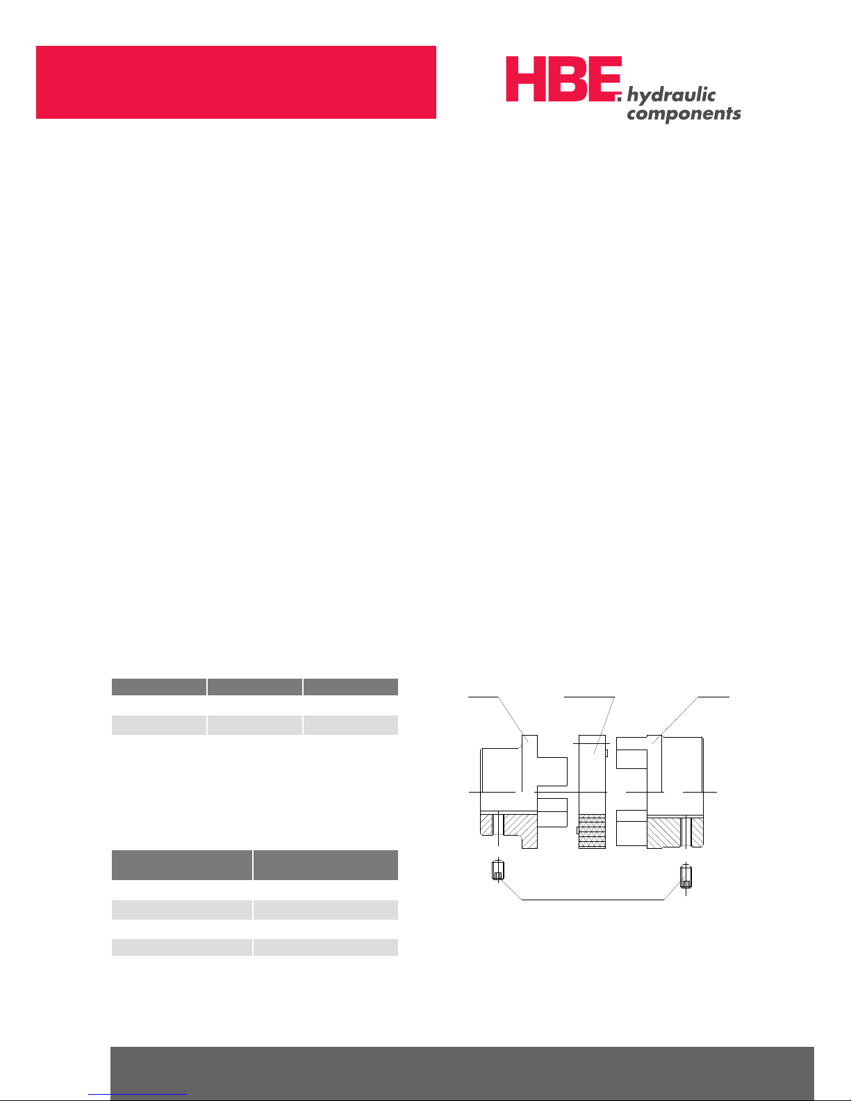
ATTENTION!
When mounting the coupling, please ensure that the
dimension E (see Technical Data) must absolutely be
kept, so that the gear ring is axially movable during
operation. Disregard might lead to damages.
• After mounting of the hubs to the shafts of the drive and
load side, the dimension “E” must be adjusted by relo-
cation of the aggregates or the hubs on the shafts.
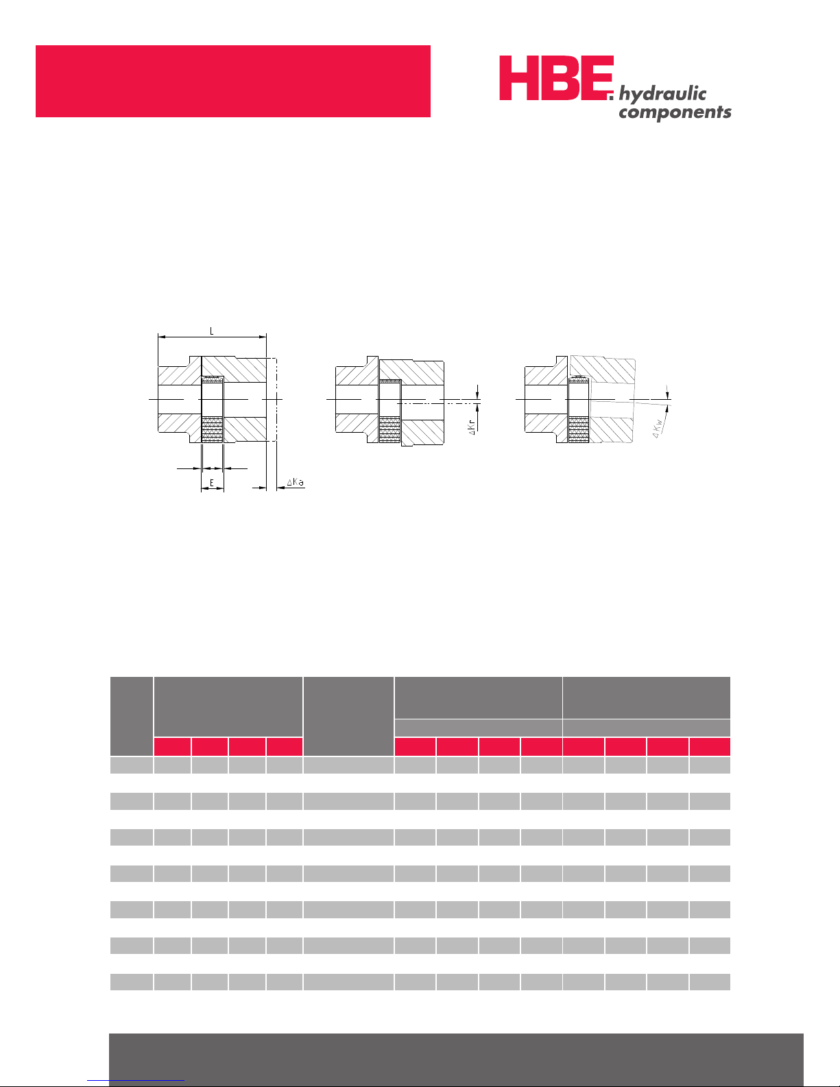
• Shafts with inserted feather key and a smaller diameter
than the inner diameter of the gear ring dh may reach
into the gear ring. The distance between the shafts must
not be lower than 50% of the dimension “E”.
• For securing the hubs by relocation, please tighten the
locking screw with corresponding starting torque
(Table 5.3).
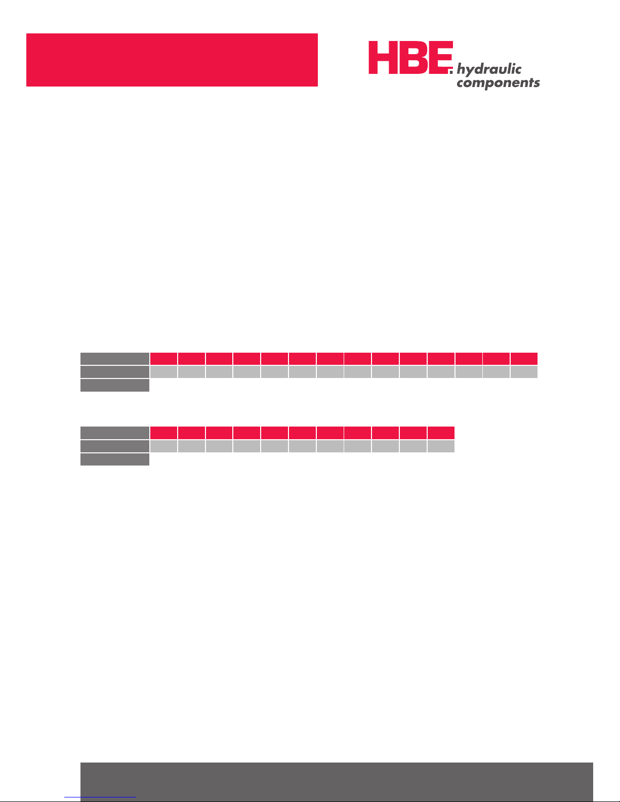
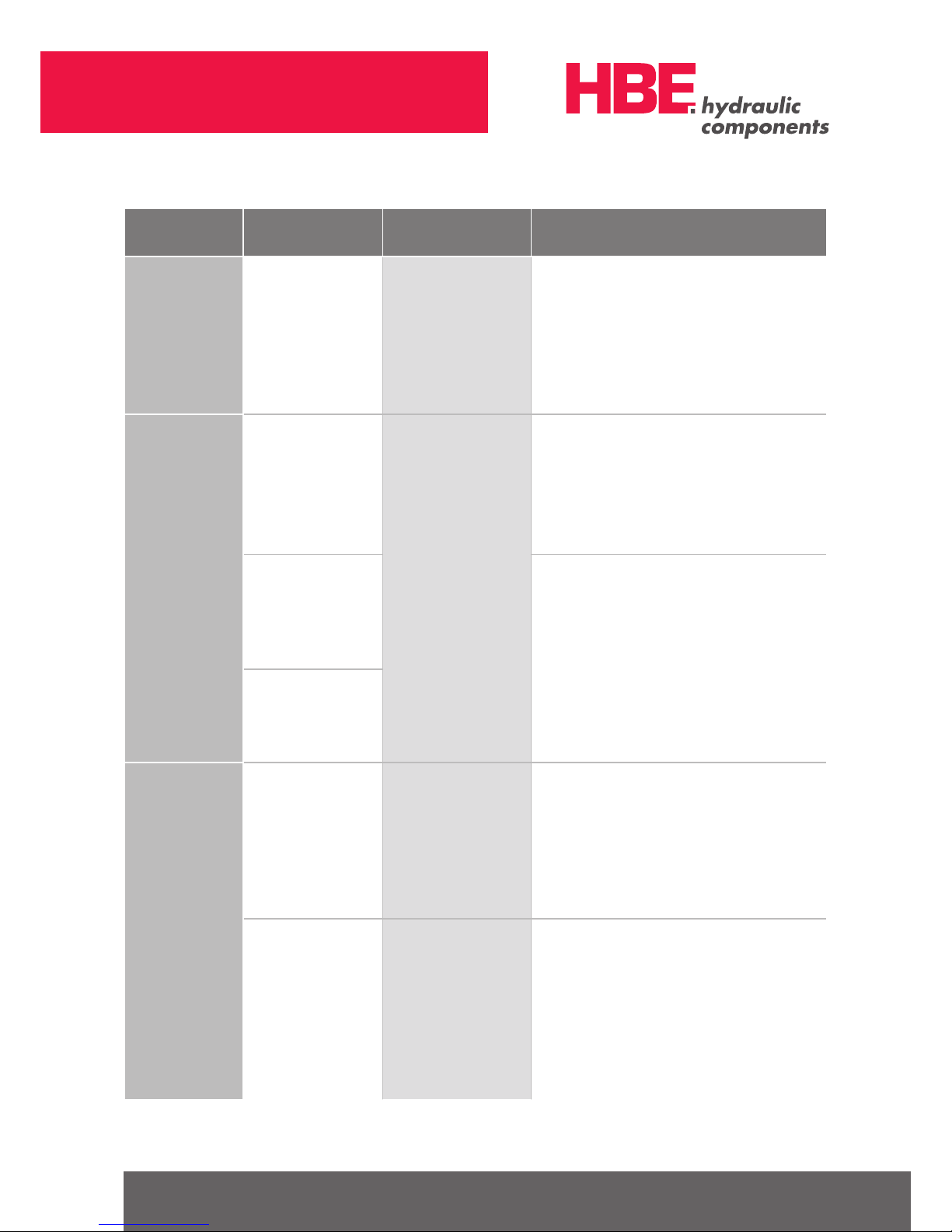
TYPE 14 19 24 28 38 42 48 55 65 75 90 100 110 125
THREAD M4 M5 M5 M6 M8 M8 M8 M10 M10 M10 M10 M12 M16 M16
TORQUE Nm 1.5 2 2 4,8 10 10 10 17 17 17 17 40 80 80
TYPE 14 19 24 28 38 42 48 55 65 75 90
THREAD M3 M6 M8 M8 M10 M10 M10 M12 M12 M16 M20
TORQUE Nm 1.34 10.5 25 25 60 60 60 100 100 250 490
Tightening torques of the locking screws
Tightening Torques of the locking screws for clamping hubs