ASC ASC300LW User manual
_____________________________________________________________________
ATLANTIC SATELLITE CORPORATION
MODEL ASC300LW
BEACON RECEIVER
1
Model ASC300LW
Beacon Receiver
Instruction Manual
Rev. 351-4-0111
www.atlanticsat.com
www.beaconreceiver.net
Atlantic Satellite Corporation
259 Expressway Court
Virginia Beach, Virginia 23462
Phone: 757-318-3500
Fax: 757-318-7020

_____________________________________________________________________
ATLANTIC SATELLITE CORPORATION
MODEL ASC300LW
BEACON RECEIVER
2
Model ASC300LW
Beacon Receiver
Table of Contents Pages
1.0 Functional Description 3
2.0 System Specifications 3
2.1 Physical Specifications 3
2.2 Environmental Specifications 3
3.0 Front Panel Facilities 4
3.1 Local Operation 4
3.11 Changing Frequency 4
3.12 Changing Gain 5
3.2 Display 5
4.0 Rear Panel Facilities 6
5.0 Serial Communications 8
6.0 Using the ASC Simple User Interface Program 10
7.0 Warning Notice 15
8.0 Warranty 16
9.0 Repair Service Policy 17
10.0 CE Declaration of Conformity 17
11.0 Continuous Digital Streaming (OPTIONAL) 18

_____________________________________________________________________
ATLANTIC SATELLITE CORPORATION
MODEL ASC300LW
BEACON RECEIVER
3
Model ASC300LW
Beacon Receiver
1.0 Functional Description
The Model ASC300LW Beacon Receiver is a high performance unit that is
designed to real time track the power density of a satellite beacon and output a
DC voltage that is linearly proportional to the beacon power. The applications for
the ASC300LW are for antenna step track controlling and uplink power control
systems.
2.0 System Specifications:
Input Frequency ........................................................................................930 to 2300 MHz
Pre-detection Bandwidth........................................................................................... 50 kHz
Input Level.......................................................... -90 dBm, minimum; -30 dBm, maximum
For full tracking range capability
Frequency Tuning ............................................................................................10 kHz Steps
Frequency Adjust...........................................................................Front Panel or Remotely
AFC (1) ..................................................................................................................+ 23 kHz
Threshold ....................................................................................<45 dB-Hz for acquisition
Input Impedance ......................................................................................................75 Ohm
Input Connector ............................................Type F female STD (N-type female optional)
Output Impedance............................................................................100 Ohm, single ended
Output Connector...............................................................Terminal plug and BNC Female
Tracking Response........................................ 0 to +10 VDC for a 20 dB input level change
System Level Adjust.......................................................................0 to 60 dB, 0.5 dB steps
Frequency Stability .............................................................................................. + 1.0 ppm
Frequency Reference ...............................................................................10 MHz (Internal)
Phase Noise....................................................................... > 75 dB-Hz, 1 kHz from Carrier
Alarms...................................................................................................................Unit Lock
Alarm Relay............................................................................................................. Form-C
LNB Voltage..................................... +18VDC, Switchable from rear panel, 300 ma, max.
M & C ....................................................... RS-232 or RS-485, Switchable, from rear panel
M & C Connector .......................................................................................... DB-9, Female
Streaming.....................................................................................DB-9, Female, (optional)
Ethernet Interface...............................................................................RJ-45 Jack (optional)
2.1 Physical Characteristics:
Size ............................................................................................. 1.75 “H X 16”D X 19”W
Weight............................................................................................................ 8 lb. (3.63 kg)
Primary Power .......................................................................90-264VAC 47 – 63Hz, 1.4A
2.2 Environmental Specifications: Tested in accordance with MIL-STD-2164
Operating Temperature .....................................................................................0
0
c to +50
0
c
Storage Temperature..................................................................................... -40
0
c to +70
0
c
Humidity .....................................................................................................95% RH@ 40
0
c

_____________________________________________________________________
ATLANTIC SATELLITE CORPORATION
MODEL ASC300LW
BEACON RECEIVER
4
3.0 Front Panel Facilities
RES: Pressing the RES (Reset) button reboots the unit. The unit will retain the
parameters of the previous settings.
LOC/REM: While depressing and holding the LOC/REM button and depressing and
releasing the RES button, the unit will toggle between the local and
remote mode of operation. In the local mode all parameters can be
controlled from the front panel facilities. The remote M&C is not
functional in the LOCAL mode of operation.
3.1 Local Operation
3.11 Changing Frequency
FSET: The FSET button activates the cursor. When depressed and released the
cursors will blink over one of the frequency digits.
CURSOR: Depressing and releasing the CURSOR button will cause the cursor to
move one frequency digit to the right. When the last digit is reached, the
cursor will jump to the first frequency digit. When the desired digit is
selected, the value of that digit may be changed.
UP: While in the FSET mode, the UP button increases the value of the
selected frequency digit.
DOWN: While in the FSET mode the DOWN button decreases the value of the
selected frequency digit.
When the desired frequency is selected depress and release the FSET
button. The cursor will no longer be displayed and the unit will be tuned to
the desired input frequency.
3.12 Changing Gain
When the unit is in the LOCAL mode of operation, the attenuation of the
input signal level can be changed to accommodate the variations in the
beacon input signal strength level. The attenuation is displayed in dB from
0 to 60 dB on 0.5 dB steps.

_____________________________________________________________________
ATLANTIC SATELLITE CORPORATION
MODEL ASC300LW
BEACON RECEIVER
5
Once the unit has been tuned to the proper input frequency and the unit
indicates that it has locked to that desired carrier then the signal strength
the attenuation can be adjusted to achieve the desired operating signal
strength voltage.
UP: The UP button increases the value of the attenuation of the unit. The
maximum attenuation setting is 60 dB and is adjustable on 0.5 dB
increments.
DOWN: The DOWN button decreases the value of the attenuation of the unit. The
minimum attenuation setting is 0 dB and is adjustable on 0.5 dB
increments.
Using the above procedure, and when the unit is locked to the desired
carrier, adjust the gain such that the front panel signal strength indication
displays +7.50 VDC. The unit tracks the input signal strength over a 20 dB
range (0.5 V/dB). For a signal strength reading of +7.5 VDC, the unit will
track upwards to +10.00 VDC or a +5 dB increase in input signal strength
and downwards to 0.00 VDC or a –15 dB decrease in signal strength. The
signal strength is not only displayed on the front panel but is also available
for interfacing to external devices by utilizing the rear mounted terminal
plug.
3.2 Display
The front panel display is a 2 x 20 VFD (vacuum fluorescent display). The
display provides operating as well as alarm indication.
F
: 930.00 to 2300.00 MHz on 10 kHz increments
ATTEN
: 0 to 60 dB on 0.5 dB steps.
REM:
Displayed in the lower left corner when the unit is in the
REMOTE
mode of operation.
ALM:
Continuously displayed if the unit is not locked to the carrier. The
green LOCK front panel LED will not be lighted.
SS:
The signal strength voltage is displayed in volts DC. The range that
is displayed is 0.00 to +9.99 VDC. The normal optimum operating
level is +7.50 VDC.

_____________________________________________________________________
ATLANTIC SATELLITE CORPORATION
MODEL ASC300LW
BEACON RECEIVER
6
4.0
Rear Panel Facilities:
J1: RJ-45 (ETHERNET OPTIONAL) Not a standard install.
MODE: Selection switch for RS-232 or RS-485 external
communication.
J2: M&C
The monitor and control input is a female DB-9
connector. The pins for the appropriate interface are:
RS-232: Pin 2 – Transmit
Pin 3 – Receive
Pin 5 – Ground
RS-485 (optional):
Pin 6 – Transmit +
Pin 7 – Transmit -
Pin 8 – Receive –
Pin 9 – Receive +
Pin 5 – Ground
TB1:
Term. 1: Alarm relay common contact
Term. 2: Alarm relay normally open contact
Term. 3: Alarm relay normally closed contact
Term. 4: AFC voltage. When the unit is locked to the carrier the
voltage will be approx.2.05 VDC.
Term. 5: Signal Ground
Term. 6: Signal strength output voltage (SS)
J3: SIGNAL STRENGTH (BNC) The signal strength voltage ranges
from 0 to + 10 VDC as a function of input signal level. The voltage slope
is 0.5 V/dB over a 20 dB input signal change.
S2: LNB Voltage, +18 VDC, 500 ma, max., Switchable In/Out on input
connector center conductor.
AC RECEPTACLE: 90-264 VAC, 47-63 Hz Input, auto-sensing. Spare
fuse compartment within receptacle.\

_____________________________________________________________________
ATLANTIC SATELLITE CORPORATION
MODEL ASC300LW
BEACON RECEIVER
7
SIGNAL STRENGTH OUTPUT CIRCUIT
J4: STREAMING (OPTIONAL) Not a standard install.
Refer to the attachment to the manual if this option is installed.
S2: (Not installed)
LNB PWR: +18 VDC, On/Off
LNB POWER LED: Red LED that is ON when power is applied to the
LNB.
J5: INPUT The frequency input range is 930 to 2300 MHz with an input
level range of –30 to –90 dBm per beacon carrier.
J5 Input: Type-F Female 75 ohm
J6 Input: 50 ohm, N-type, female connector, Optional
J7 Input: (SMA optional)

_____________________________________________________________________
ATLANTIC SATELLITE CORPORATION
MODEL ASC300LW
BEACON RECEIVER
8
5.0 Serial Communications:
REMOTE OPERATION
Note: The unit must be placed in the remote mode of operation to perform any serial
communication functions. Select the interface mode (RS-232 or RS-485) by
placing the rear mounted mode switch in the appropriate position.
The unit can be remotely monitored and commanded by use of an RS-485, 4-wire,
interface or an RS-232, 2-wire interface. The serial protocol is the same for both
modes and is as follows:
2400 Baud, No parity, eight data bits, one stop bit
(2400,N,8,1)
The unit can be assigned a Hex address within the range of values of 1 Hex to F Hex.
The assignment of the unit address is accomplished by the following sequence:
1. Place the unit in the REM (remote) mode of operation by depressing and holding
the LOC/REM button and depressing and releasing the RESET button. The unit
will toggle between the LOCAL and REMOTE mode of operation. When the
REMOTE mode is selected, REM will be displayed in the lower left corner of
the front panel display.
2. To select the address for the unit, press and release the UP or DOWN buttons
until the desired address is selected in the range of NO or 1to F where NO
means that no unit addressing is required and 1to F requires that the hexadecimal
equivalent of the selected address must be sent to communicate with the unit.
3. The unit needs to be left in the REM mode of operation for external control of
the unit.
To poll the unit for operating status when the unit is in addressing mode of 1 to F,
transfer the following sequence:
ADDRESS (HEX) <space>0<space>0<space>0<space>
The unit will respond back with the current operating settings and alarm conditions
AD=address, F=f4f3f2f1.k2,k1, ATT=AT3,AT2 . AT1, SS=v2,v1.m1,m2
Where address is the hex value of the unit, f4f3f2f1 is the operating frequency in
MHz, k2, k1 is the operating frequency in kHz, AT3, AT2, . AT1, is the attenuation
setting in dB from 0.0 to 60.0, v2, v1,m1, m2 is the signal strength in volts from 9.99
to 0.00.
If an alarm condition exits, the unit is out of lock, and then the signal strength voltage
will not be displayed and will be displaced with the word ALARM.
To change parameters of the unit transmit the following command string:

_____________________________________________________________________
ATLANTIC SATELLITE CORPORATION
MODEL ASC300LW
BEACON RECEIVER
9
Address (Hex) <space>f4f3f2f1<space>k2k1<space>at3,at2,at1<space>
Where address is the Hex value of the assigned address, f4 is the most significant
digit of frequency in MHz, k2 is the most significant digit in kHz, g3 is the most
significant digit of gain. The range of frequency is 950.00 to 2300.00 and the range of
attenuation is 0 to 600. If a frequency of less than 950 or greater than 2300 and/or an
attenuation of greater than 600 or a least significant digit of a number other than 0 or
5 is transmitted then ? will be transmitted back. The address, frequency in MHz and
kHz and gain must be simultaneously transmitted. They cannot be transmitted
independently.
The attenuation of the unit can be changed by transmitting any number from 0 to 600.
The least significant digit must either be a 0 or a 5. 0 corresponds to 0.0 dB
attenuation and 600 corresponds to 60.0 dB of attenuation. To change the attenuation
by 0.5 dB, the least significant digit must be a 5. For example, to change the
attenuation setting to 26.5 dB, the number string 265 must be transmitted.
An example to change frequency and attenuation is:
A (Hex) <space>1210<space>99<space>265<space>
The unit will change to 1210.99 MHz and an attenuation of 26.5 dB.
To poll the unit to see if the changes have been made transmit the following
sequence;
A (Hex) <space>0<space>0<space>0<space>
The unit will echo back the following:
AD=A,F=1210.99,ATT=26.5,SS=(As determined)
If there was an alarm conditions the unit would echo back at the end of the response
string the word ALM.
If the unit has NO selected as the address then no address is necessary as a preface to
the serial commands.
To poll the unit to see if the changes have been made transmit the following
sequence;
0<space>0<space>0<space>
All other commands are the same as described above with the exception that the
address character does not need to proceed the command structure.
_____________________________________________________________________
ATLANTIC SATELLITE CORPORATION
MODEL ASC300LW
BEACON RECEIVER
10
6.0 ASC300 Series Using the ASC Simple User Interface Program:
The ASC300 series beacon receivers can be remotely controlled and polled utilizing the
included terminal program. Shown below are various screens that have been preset for
communicating with the unit.
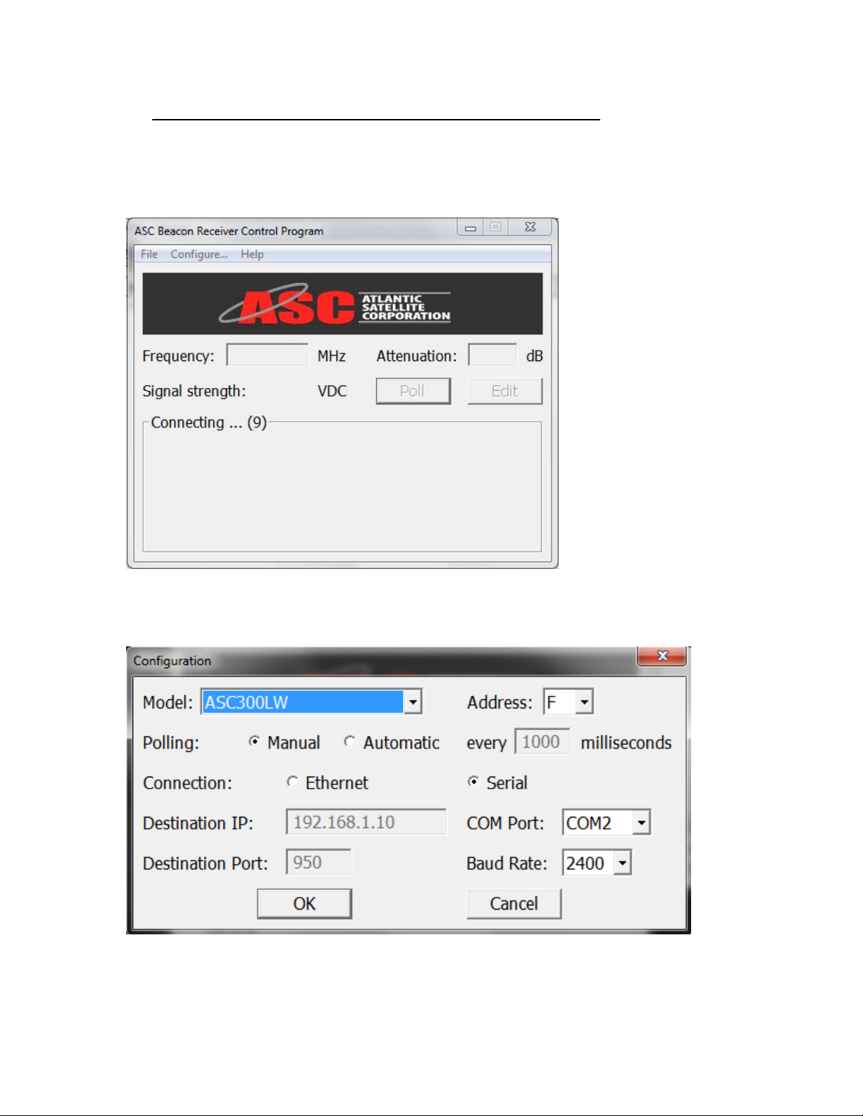
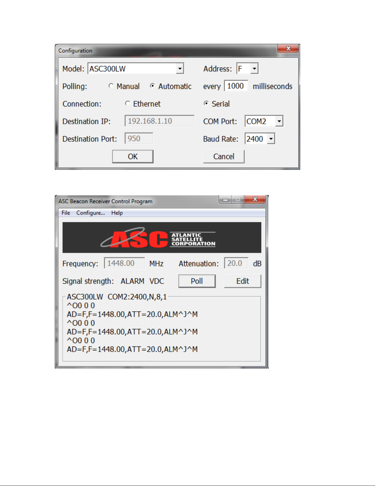
When you initially open the ASC Beacon Receiver Control Program, the above screen
will appear. Click on Configure and the following screen will appear.
_____________________________________________________________________
ATLANTIC SATELLITE CORPORATION
MODEL ASC300LW
BEACON RECEIVER
11
On the Model pull down screen select the model that you will be working with. In this
case you will see that the model ASC300LW has been selected. You will also see that
the baud rate has been set at 2400 and the Address has been set to F. Note all other
ASC300 series beacon receiver baud rates should be set to 2400. Set the connection to
Serial. Select the COM Port to be used. In this case the COM2 has been selected. Note:
if the Ethernet Options is installed you can also set the Destination IP & Port at this
time. Click OK.
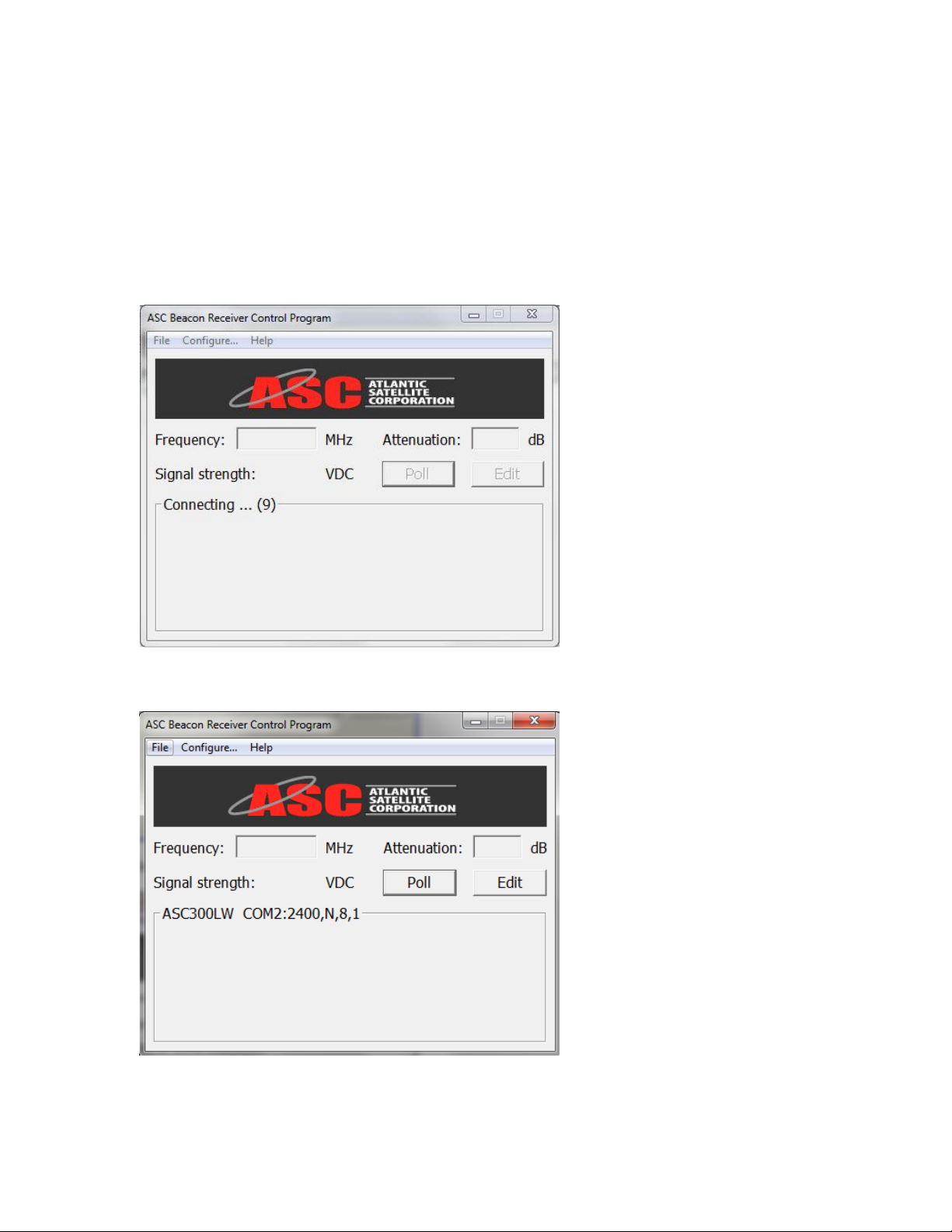
If the selected Com port is not supported then the following screen will appear.
If the selected Com port is supported then the following screen will appear.
Click on the Edit button and the below screen will appear.

_____________________________________________________________________
ATLANTIC SATELLITE CORPORATION
MODEL ASC300LW
BEACON RECEIVER
12
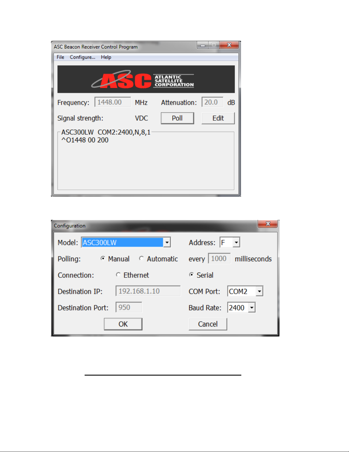
Enter the desired beacon frequency and attenuation for the unit in the appropriate boxes.
The frequency range is from 930.00 to 2300.00 on 10 kHz steps. The attenuation range is
0.0 to 60.0 on 0.5 dB steps. It is recommended that the unit be initially set at an
attenuation of 20.0 dB.
Click OK and the selected parameters will be transmitted to the unit and the following
screen will appear.
_____________________________________________________________________
ATLANTIC SATELLITE CORPORATION
MODEL ASC300LW
BEACON RECEIVER
13
Select and click on Configure. The following screen will appear.
On the above screen the user can select that the unit can be polled manually by clicking
the POLL button on the previous screen or can be selected to automatically poll by
selecting Automatic. In the Automatic mode the polling time in milliseconds can be set
by the user. Do not use a polling rate of less than 300 milliseconds.
_____________________________________________________________________
ATLANTIC SATELLITE CORPORATION
MODEL ASC300LW
BEACON RECEIVER
14
Click OK and the following screen will appear.
In the above screen the transmitted command ^O 0 0 0, the poll command, followed by
the unit response. The trailing characters ^J^M are the control characters for line feed
and carriage return. The signal strength is separately displayed after the line Signal
strength:
This completes the set up of the ASC Beacon Receiver Control Program.

_____________________________________________________________________
ATLANTIC SATELLITE CORPORATION
MODEL ASC300LW
BEACON RECEIVER
15
7.0 Notice:
This publication and its contents are proprietary to Atlantic Satellite Corporation or ASC
and intended solely for the contractual use of its customers for no other purpose than to
install and operate the equipment described herein. This publication and its contents shall
not be used or distributed for any other purpose and or communicated, disclosed, or
reproduced in any way whatsoever without the prior written permission from Atlantic
Satellite Corporation.
For the proper installation and operation of this equipment and or all parts thereof, the
instructions in this guide must be strictly and explicitly followed by experienced
personnel. All of the contents of this guide must be fully read and understood prior to
installing or operating any of the equipment or parts thereof.
FAILURE TO COMPLETELY READ AND FULLY UNDERSTAND AND
FOLLOW ALL OF THE CONTENTS OF THIS GUIDE PRIOR TO
INSTALLING AND OR OPERATING THIS EQUIPMENT, OR PARTS
THEROF, MAY RESULT IN DAMAGE TO THE EQUIPMENT, OR PARTS
THEREOF, AND TO ANY PERSONS INSTALLING AND OR OPERATING THE
SAME.
Atlantic Satellite Corporation does not assume any liability arising out of the application
or use of any products, components parts, circuits, software, firmware described herein.
Atlantic Satellite Corporation further does not convey any license under its trademark,
copyright, or common-law rights nor the similar rights of others. Atlantic Satellite
Corporation further reserves the right to make any changes in any products, or parts
thereof, describe herein without notice.
Warning! Shock Hazard!
Do Not Open The Equipment! Service Only By ASC Personnel Only!
The Model ASC300LW contains no user-serviceable parts. Do not attempt to service
this product yourself.
ANY ATTEMPT TO DO SO WILL NEGATE ANY AND ALL WARRANTIES.

_____________________________________________________________________
ATLANTIC SATELLITE CORPORATION
MODEL ASC300LW
BEACON RECEIVER
16
8.0 Warranty:
Atlantic Satellite Corporations Warranty Policy ASC2006-05-20
Atlantic Satellite Corporation (ASC) (Seller) warrants the items manufactured and sold by ASC to be free
of defects in material and workmanship for a period of two (2) years from date of shipment. ASC’s
obligation under its warranty is limited in accordance with the periods of time and all other conditions
stated in all provisions of this warranty.
This warranty applies only to defects in material and workmanship in products manufactured by ASC. ASC
makes no warranty whatsoever concerning products or accessories not of its manufacture. Repair, or at
ASC’s option, replacement of the ASC products or defective parts therein shall be the sole and exclusive
remedy for all valid warranty claims.
Warranty Period
The applicable warranty period shall commence on the date of shipment from ASC’s facility to the original
purchaser and extend for the stated period following the date of shipment. Upon beginning of the applicable
ASC warranty period, all customers’ remedies shall be governed by the terms stated or referenced in this
warranty. In-warranty repaired or replacement products or parts are warranted only for the remaining
portion of the original warranty period applicable to the repaired or replaced products or parts. Repair or
replacement of products or parts under warranty does not extend the original warranty period.
Warranty Coverage Limitations
The following are expressly not covered under warranty:
1. Any loss, damage and/or malfunction relating in any way to shipping, storage, accident, abuse,
alteration, misuse, neglect, failure to use products under normal operating conditions, failure to use
products according to any operating instructions provided by ASC, lack of routine care and maintenance as
indicated in any operating maintenance instructions, or failure to use or take any proper precautions under
the circumstances.
2. Products, items, parts, accessories, subassemblies, or components which are expendable in normal use or
are of limited life, such as but not limited to, bulbs, fuses, lamps, glassware, etc. ASC reserves the right to
revise the foregoing list of what is covered under this warranty.
Warranty Replacement and Adjustment
ASC will not make warranty adjustments for failures of products or parts, which occur after the specified
maximum adjustment period. Unless otherwise agreed, failure shall be deemed to have occurred no more
than seven (7) working days before the first date on which ASC receives a notice of failure. Under no
circumstances shall any warranty exceed the period stated above unless expressly agreed to in writing by
ASC.
Liability Limitations
This warranty is expressly in lieu of and excludes all other express and implied warranties, Including but
not limited to warranties of merchantability and of fitness for particular purpose, use, or applications, and
all other obligations or liabilities on the part of ASC, unless such other warranties, obligations, or liabilities
are expressly agreed to in writing by ASC. All obligations of ASC under this warranty shall cease in the
event its products or parts thereof have been subjected to accident, abuse, alteration, misuse or neglect, or
which have not been operated and maintained in accordance with proper operating instructions. In no event
shall ASC be liable for Incidental, consequential, special or resulting loss or damage of any kind howsoever
caused. ASC’s liability for damages shall not exceed the payment, if any, received by ASC for the unit or
product or service furnished or to be furnished, as the case may be, which is the subject of claim or dispute.
Statements made by any person, including representatives of ASC, which are inconsistent or in conflict
with the terms of this warranty, shall not be binding upon ASC unless reduced to writing and approved by
an officer of ASC.

_____________________________________________________________________
ATLANTIC SATELLITE CORPORATION
MODEL ASC300LW
BEACON RECEIVER
17
9.0 Repair Service Policy:
Warranty Repair Return Procedure
Before a warranty repair can be accomplished, a Repair Authorization must be received. It is at this time
that ASC will authorize the product or part to be returned to the ASC facility or if field repair will be
accomplished. The Repair Authorization may be requested in writing, email or by calling:
Atlantic Satellite Corp.
259 Expressway Court
Virginia Beach, Virginia 23462 USA
T: 1-757-318-3500
rma@atlanticsat.com
Any product returned to ASC for examination must be sent prepaid via the means of transportation
indicated as acceptable to ASC. Return Authorization Number must be clearly marked on the shipping
label. Returned products or parts should be carefully packaged in the original container, if possible, and
unless otherwise indicated, shipped to the above address.
Non-Warranty Repair
When a product is returned for any reason, Customer and its shipping agency shall be responsible for all
damage resulting from improper packing and handling, and for loss in transit, not withstanding any defect
or nonconformity in the product. By returning a product, the owner grants ASC permission to open and
disassemble the product as required for evaluation. In all cases, ASC has sole responsibility for determining
the cause and nature of failure, and ASC’s determination with regard thereto shall be final.
10.0CE Declaration of Conformity:
We, the Manufacturer Atlantic Satellite Corporation at the following location:
Atlantic Satellite Corporation
259 Expressway Court
Virginia Beach, VA 23462
declares, that the following product:
Product Name: Beacon Receiver
Model Number: ASC300L ASC300L-D ASC300LW ASC300LW-D
The product complies with the requirements of the following Directives:
•LVD Directive 73/23/EEC (as amended by 92/C210/01 and 93/68/EEC)
•EMC Directive 89/336/EEC (as amended by 92/31/EEC and 93/68/EEC)
and conforms to the following standards:
•EN 60950:1992 +A1, A2, A3:1995 AND A4:1996
•EN 55022:1987 class A. sections 4 & 5
•EN 50082-1:1992 Part 1, commercial &light Industry
•IEC 801-2:1991, 4kV CD, 8kV AD
•IEC 801-3:1984, 3V/m
•IEC 801-4:1988, 2.0 kV Main, 1kV Signal & Control Lines
Warning notice:
•This equipment is intended for commercial and light industrial use only.
•This is a Class “A” product. In a domestic environment this product may cause radio
interference in which case the user may be required to take adequate measures.

_____________________________________________________________________
ATLANTIC SATELLITE CORPORATION
MODEL ASC300LW
BEACON RECEIVER
18
11.0 Continuous Digital Streaming 351L STREAMING
The streaming option associated with the ASC351L series of beacon tracking receivers provides a
continuous data stream running at 9600 baud that contains signal strength level indication in
centiVolts as well as lock or alarm condition of the unit. A dedicated DB-9 (J4), on the rear of
theunit, provides the RS-232 streaming interface. The DB9, RS-232, pin out is:
Pin 2: serial output
Pin 5: ground
The protocol for the data stream is as follows:
9600,N,8,1
There is a 500 ms delay between transmissions.
The output data format is:
#(delimiter)1 or 0 (Lock or Alarm), space, followed by the signal strength voltage in centiVolts
(cV).
As an example, for signal strength of 7.50 Volts and the unit locked the data string would be:
#1 750
If the unit is not locked the data string would be:
#0 0
Table of contents


