3M Dyantel 2250 User manual

September 1999
78-8097-6518-9-B
Dynatel™2250
Advanced Cable Locator
Operators Manual

TABLE OF CONTENTS
Introduction ............................................................................... 2
Installing or Replacing the Batteries ........................................ 2
Initial Receiver Configuration .................................................. 3
Receiver Battery Test ................................................................ 3
Transmitter Battery Test ........................................................... 4
Using External DC Power ......................................................... 4
Locating a Buried Cable ........................................................... 5
Transmitter Setup ................................................................ 5
Direct Connect Method ...................................................... 6
Dyna-Coupler Method ........................................................ 8
Induction Method ................................................................ 9
Receiver Setup .................................................................... 10
About Trace Modes ............................................................. 11
Selecting Passive Power Frequencies ................................. 12
Selecting Auxiliary Frequencies ......................................... 12
Determining Cable Depth and Current .............................. 13
Using Current Indications During Locating ...................... 14
Locating an Active Duct Probe (ADP) ..................................... 15
Determining ADP Depth .................................................... 15
Locating EMS Markers ............................................................. 16
Locating Markers while Tracing Cable Path ...................... 16
Locating Markers Using the receiver ................................. 16
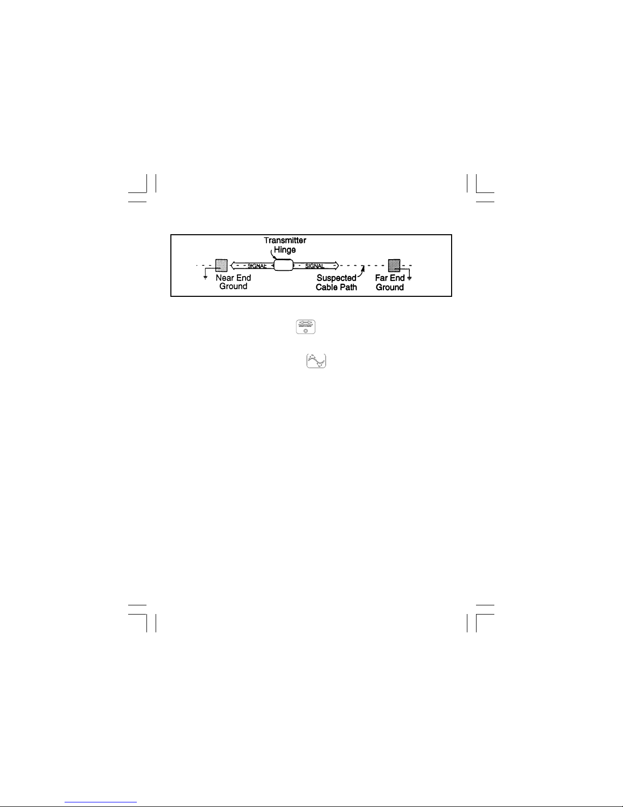
Toning Aerial Faults .................................................................. 17
Transmitter Setup ................................................................ 17
Receiver Setup .................................................................... 17
Cable or Pair Identification ....................................................... 18
Transmitter Setup ................................................................ 18
Cable Identification Receiver Setup ......................................... 18
Pair Identification Receiver Setup ............................................ 19
Optional Accessories ................................................................. 20
Technical Information ............................................................... 21
Page 1

INTRODUCTION
The 3M™Dynatel™2250 Advanced Cable Locator consists of a Transmitter
and a Receiver for locating buried cables or Active Duct Probes (sondes).
It also measures and pinpoints conductor faults in aerial cables. The
Transmitter provides four frequencies to accommodate varying factors
such as distance, cable type, or soil conditions. If desired, all four
frequencies may be transmitted at once. The Transmitter also provides a
separate Tone function for identifying cables and pairs. The Receiver
provides four locating modes to accomplish fast or difficult tracing and to
pinpoint or verify a buried cable. The Receiver detects 50 or 60 Hz AC
Power signals and also measures the signal current in a cable and displays
its magnitude. The depth of buried cables or sondes may also be displayed.
Note: For more detailed locating instructions and advanced locating
techniques, ask your 3M sales representative or call 800/426-8688 for a
free publication called Cable and Pipe Locating Techniques.
INSTALLING OR REPLACING THE BATTERIES
Battery Disposal: Since regulations vary, consult applicable regulations
or authorities before disposal.
6 'C'
cells
6 'AA'
cells
CAUTION!
Do not connect batteries improperly, charge or dispose of in fire.
Batteries may leak or explode and cause personal injury. Always
remove batteries when storing the units.
Page 2

INITIAL RECEIVER CONFIGURATION
Display depth units (inches, feet and inches, or centimeters) may be
changed while holding and pressing .
For each press, one of
three units will display. To change the passive Power frequency, press and
hold then press to toggle between 50 or 60 Hz as displayed in
the lower left corner of the display.
To change the Null bar graph display mode, press and hold
then
press to toggle between normal Null bar graph display (Null flag will
flash) and inverse Null bar graph display (Null flag is solid). See section
About Trace Modes (Page 11) for further information.
Page 3
RECEIVER BATTERY TEST
The Receiver batteries are tested for two seconds every time the unit is
turned on. The time interval can be extended by pressing and holding .
During the battery test, the bar graph should extend to the right of the
battery level mark, otherwise replace the batteries.
Note: When batteries are low, the battery test indicator will flash.
Battery Test
Indicator
Battery Level
Mark

TRANSMITTER BATTERY TEST
To test the Batteries, press and hold . Listen to the tone and watch
the display.
• solid tone and 'OK' indicates batteries good;
• beeping tone and 'LO' indicates batteries low;
• no tone and '- -' indicates replace batteries.
Note: The battery test indicates battery condition for normal output
levels. If the unit resets when the high output level is selected, use the
normal output level or replace the batteries.
USING EXTERNAL DC POWER AND 5 WATT OUTPUT
If the unit has the option A, the Transmitter can be operated from an
external 12VDC source as well as its internal batteries. Use the supplied
cigarette lighter adapter cable to connect the DC power from a vehicle's
battery source to the Transmitter's external power jack located next to the
output jack.
Note: The internal batteries will not be recharged with external DC.
5 Watt Output
An external DC source is required for 5 watt output. To select 5 watt
operation, press once for high output (3W) and again for 5 watt
operation. The High Output flag will turn on for 3W and flash for 5W.
Page 4

LOCATING A BURIED CABLE
Transmitter Setup
Perform a battery test and then connect the Transmitter using one of the
three methods below to put tracing signal on a cable.
Note: Key descriptions can be found inside the Transmitter lid.
DANGER!
Voltage greater than 240 volts will damage equipment and cause
personal injury and death. Make all direct test connections before
turning on the Transmitter. Then activate the Transmitter in the Ohms
mode and check the display for voltage readings. Follow standard
procedures for reducing the voltage.
WARNING!
Potential for electrical shock exists when handling connecting cables
while the Transmitter is in the TRACE, FAULT or TONE modes. Turn
the Transmitter off before handling connecting cables.
Page 5

Make sure the Transmitter is off. Plug the direct connect cable into the
front panel jack. Connect the Black clip to the ground rod. Place the
ground rod in the earth perpendicular to the suspected cable path. If
necessary, extend the black lead with the Ground Extension Cable. Next,
remove the ground bonding and attach the Red clip to the shield.
Press to turn the Transmitter on in the Ohms mode . It will
measure the continuity of the cable under test. The results are displayed in
ohms and as a tone (solid tone = good ground; beeping tone = usable
ground; no tone = poor or no ground).
Note: In the ohms mode, the Transmitter can detect voltage as well as ohms. If a
low voltage is detected, the display will alternate between displaying ohms and
volts. When displaying ohms, the flag over the will be visible. When displaying
volts, the flag over the 'V' will be visible. When the voltage magnitude is sufficient
to impair the accuracy of the ohms measurement, only voltage will be displayed. If
the voltage is AC, a sine wave will be visible on the display. If a high AC
voltage is detected, a rapid beeping tone will be heard.
Note: Never attach or remove the direct connect cable from the Transmitter front
panel jack while the red and black clips are connected to a cable.
Direct Connect Method
Page 6

Press to select Trace mode. Press again to select one or all of the
four frequencies. The display will alternate between displaying the
selected frequency and the output signal current. It is best to choose the
lowest frequency for direct connect with far-end ground and a high
frequency for direct connect with no far-end ground.
Press to select high output level for longer tracing distances and
deep cables.
Transmitter setup is finished, now go to LOCATING A BURIED
CABLE - RECEIVER SETUP (Page 10).
Page 7

Dyna-Coupler Method
Cable Path
Connect the Dyna-Coupler to the Transmitter front panel jack using the
coupler cable.
Clamp the Dyna-Coupler around the cable below any bonds just before the
cable enters the earth. The jaws of the coupler must fully close.
Press to turn Transmitter on. Press again to select 8, 33, or 200 kHz.
Select high output level by pressing .
Transmitter setup is finished, now go to LOCATING A BURIED
CABLE - RECEIVER SETUP (PAGE 10).
Page 8

Induction Method
Place the transmitter on the ground over the target cable with the lid hinge
in line with the cable path. Press to turn the Transmitter on.
Press again to select either 33 kHz or 200 kHz. For greater tracing range,
select high output level by pressing .
Note: If the Receiver is less than 50 feet from the Transmitter, it can pick
up signal through the air. For best results, keep the Receiver away from
the Transmitter by at least that distance.
Transmitter setup is finished, now go to LOCATING A BURIED CABLE
- RECEIVER SETUP (PAGE 10).
Page 9

LOCATING A BURIED CABLE
Receiver Setup
Note: Key descriptions can be found on the side of the Receiver.
Press to turn the Receiver on.
Press to select the power frequency (see section on Selecting
Passive Power Frequencies on Page 12)for passive locating; otherwise,
select the same frequency as the Transmitter.
Press to adjust the speaker volume as needed: off, normal, high, or
high-expanded. The high-expanded setting causes the audio to cut off
below a certain threshold.
Press to select a locate mode (Peak , Null , or Diff
). To select Special Peak mode: from Peak mode, press and hold
then press to toggle between Peak and Special Peak modes.
While in Special Peak mode, the peak flag will flash.
Note: Peak, Special Peak, or Null mode may require re-setting the
Receiver gain. Press when the bar graph remains either fully open or
fully closed. This is not necessary in differential mode since the unit
automatically adjusts the receiver gain.
Page 10

About Trace Modes
Peak: In this mode, as the antenna crosses the cable, the Receiver speaker
volume increases to a maximum and the bar graph fills from both sides
toward the middle. As the antenna moves off the cable path, the speaker
volume decreases and the bar graph opens.
Peak with High-Expanded: While in Peak mode, press to select
High-Expanded (the highest setting). Speaker response is cut off as the
antenna moves away from the cable.
Null: In this mode, the signal is a minimum directly over the cable and is
maximum on either side of the cable. The speaker volume and display
signal strength correspond to the signal being received. In the normal bar
graph display mode (Null flag flashing) the bar graph opens at low signal
strength and closes at high signal strength. In the inverse Null bar graph
display mode (Null flag is on solid), the bar graph closes at low signal
strength and opens at high signal strength.
Differential: In this mode, the Receiver provides an indication of the
relative position of the cable to the Receiver by displaying right or left
arrows (the arrow points toward the cable). The bar graph increases to a
maximum as the Receiver antenna is moved directly over the cable path.
Speaker response is a high warbling tone to the right of the cable path, a
low warbling tone to the left, and a solid tone directly over the cable.
Special Peak Mode: This mode will increase the signal sensitivity of the
Receiver when the signal is too weak for normal tracing. Use special
attention when using this mode because it is more susceptible to congestion
than the normal peak mode.
Numerical Signal Strength Display Resolution: The user may select
between 3 levels of signal strength resolution. The setting will be displayed
on the right end of the bar graph during selection.To change the setting,
press and hold the key during power up then press the key.
Display resolution may be changed between the standard 1X, (no bars
illuminated), 2X, (One bar illuminated), and 4X (Two bars illuminated).
The unit saves the last setting until changed.
Note: While tracing cables, keep the Receiver handle in line with the
suspected cable path.
Page 11

Selecting Passive Power Frequencies
See section Initial Receiver Configuration (Page 3) to set the power
frequency to 50 Hz or 60 Hz. The Receiver can be tuned to locate 3
different harmonics of the chosen power frequency.
H50 Hz or H60 Hz (high harmonic): Best for general locating of
passive power.
L50 Hz or L60 Hz (low harmonic): Works best on primary power
cables. May be used when high harmonic is weak or erratic.
100 Hz or 120 Hz : For locating rectified AC power signals, often
found on pipelines using impressed current cathodic protection.
When a Power frequency is selected, the Hz symbol will flash, indicating
that alternate frequencies are available. To change the selected power
frequency, press and hold then press to select the next Power
frequency.
Selecting Auxiliary Frequencies
Auxiliary frequencies are used to trace cables without using frequencies
supplied by the 2250 transmitter. the Receiver may be able to detect these
auxiliary frequencies, depending on the model:
31 kHz: For locating in-service CATV cables.
512 Hz, 560Hz or other frequencies for locating cables connected to a
remote location transmitter with that frequency.
If your Receiver has multiple auxiliary frequencies, the Hz symbol will
flash when one is selected. To change the selected auxiliary frequency,
press and hold then press to select the next auxiliary frequency.
Page 12

DETERMINING CABLE DEPTH AND CURRENT
Place the Receiver Antenna on the ground directly above the cable with
the handle parallel to the path. Press and the display will indicate
the cable depth and relative current . Current is displayed in the lower
left corner of the display. Press twice to continue tracing. You may
also press to return to Trace mode.
Note: During a depth-current measurement, the display will exhibit
' – – – ' when the received signal is too low, too high, or erratic.
Page 13

Using Current Indications During Locating
Both the Transmitter and Receiver will indicate cable current. These
current indications will help to select a trace frequency, identify the correct
cable and troubleshoot the set up.
When using the direct connect method, the Transmitter output current
number is displayed. A "LO" display, or number less than 50, indicates a
weak tracing signal. A number higher than 70 represents a strong tracing
signal. When the Receiver is used to find the cable near the Transmitter
connection point, the current number displayed in the Receiver should
correspond (within 5 points) to the Transmitter number, if: you are over the
correct cable, AND most of the signal is flowing in that cable.
Note: On the Transmitter every ten units on the current display represents
a factor of two in current magnitude. On the receiver, trace current
readings for 512Hz, 560 Hz and all additional auxiliary frequencies
(except 31.5 kHz) are displayed in milliamps. For all other trace
frequencies every ten units on the current display represents a factor of two
in current magnitude.
When the Transmitter signal is applied using the Dyna-Coupler, the
Transmitter current display indicates the current in the coupler and not in
the cable. In order to get a measure of the cable current, point the Receiver
at the exposed cable about two feet from the Dyna-Coupler. This will be
the current number that should be used to identify the correct cable.
In general, when the Transmitter is set up to apply more current on the
target cable than any other cable, the cable can easily be identified because
the Receiver current reading will be highest.
Note: Since some of the signal in the cable will bleed into the earth, it is
expected that the Receiver current indication along the cable will decrease
gradually away from the Transmitter. This effect is more pronounced at
higher frequencies.
Page 14

LOCATING AN ACTIVE DUCT PROBE (ADP)
Press to turn the Receiver on.
Press to select the 33 kHz frequency.
Press to select the Peak mode . If you find that the received
signal is too weak in this mode, try the Special Peak mode. To select
Special Peak mode: From Peak mode press and hold then press
to toggle between Peak and Special Peak modes. While in this mode
the Peak flag will flash.
With the Receiver handle perpendicular to the conduit path, locate the
ADP position by moving along the path until a peak is found.
Press when the bar graph remains either fully open or fully closed.
Refer to the ADP operating instructions for further information.
Determining ADP Depth
Place the Receiver Antenna on the ground directly above the located ADP
position maintaining the handle orientation perpendicular to the path.
Press twice to display ADP depth .
To return to trace mode, press or .
Note: During a depth-current measurement, the display will exhibit
' – – – ' when the received signal is too low, too high, or erratic.
Page 15

LOCATING EMS MARKERS
EMS markers may be detected and located using either the 3M Dynatel™
2205 or 2206 EMS Marker Locating Accessory. To attach the accessory,
slide the Receiver horizontally into EMS Marker Locating Accessory
mounting slot. Make sure the locking button holds the Receiver securely in
the slot. To separate the units, press the locking button down and slide the
Receiver out of the EMS Marker Locating Accessory mounting slot.
Locating Markers while Tracing Cable Path
To detect markers while tracing the cable path, set the 2205 or 2206
accessory mode switch to the Alert position, and trace the cable path
normally. The internal buzzer in the accessory will alert you to the
proximity of a detected marker.
Note: Do not use Null or Differential modes when using the 2205 or 2206.
Locating Markers using the Receiver
If the buzzer response is too broad, the exact marker position may be
pinpointed by using the Receiver.
Select 577 Hz or 33 kHz on the Accessory. Use a different frequency from
the tracing signal.
Turn the Receiver ON, select Peak mode, and set the frequency to match
the Accessory setting.
Note: The initial Receiver gain in Peak mode is optimized for interfacing
with the 2205 or 2206 Accessory while searching for a marker. Press
only when a marker is detected and the signal is too strong. To search for
a new marker, reset the Receiver gain to the initial setting by turning its
power OFF and back ON, or pressing and then re-selecting the Peak
mode.
Refer the EMS Marker Locating Accessory operating instructions for
further information.
Press to turn the Receiver on.
Page 16

TONING AERIAL FAULTS
Transmitter Setup
Perform a battery test; then with the Transmitter off, plug the direct
connect cable into the front panel jack.
If fault is a shorted pair, connect Red clip to tip and the Black clip to ring.
If the fault is a cross (two pair involved), connect the Red clip to crossed
conductor of one pair and the Black clip to the crossed of the other pair.
If the fault is a ground, connect the Red clip to the faulted conductor and
the Black clip to ground.
Press to turn the Transmitter on in the Ohms mode to verify the
fault. Press once more to select the Tone mode .
Press to change the high output level.
Receiver Setup
Press to turn the Receiver on.
Press to select Tone mode .
Connect a toning coil to the Receiver accessory jack.
Press to select the low toning frequency (577 Hz).
Move the toning coil along the cable and find a peak signal then
press to adjust the Receiver gain.
Press to adjust the speaker volume as needed.
Follow the cable with the toning coil. An aerial fault is located at the
point where the tone stops or drops off sharply.
Page 17

CABLE OR PAIR IDENTIFICATION
Transmitter Setup
Transmitter setup is the same to identify cables or pairs, however, Receiver
setups are different. Perform a battery test; then with the transmitter off,
connect the Dyna-Coupler to the Transmitter front panel jack using the
coupler cable.
Note: Cable Identification requires two Dyna-Couplers: one at the
Transmitter and one at the Receiver.
Clamp the Dyna-Coupler around the cable or both and tip and ring of a pair
and make sure the jaws fully close.
Press to turn the Transmitter on and then twice more to select the
Tone mode .
Press to change the high output level.
CABLE IDENTIFICATION
Receiver Setup
Press to turn the Receiver on.
Press to select Tone mode .
Connect a second Dyna-Coupler to the Receiver accessory jack using the
earth frame cable or another coupler cable.
Press to select the highest toning frequency (200 kHz). Check the
first cable in the group by clamping the Dyna-Coupler around the cable.
Press and observe the numeric display, which is relative signal
strength. Remember the number and continue by clamping the Dyna-
Coupler around the next cable in the group. If the signal strength is greater
than the previous observation, press . If the signal strength is less than
before, ignore it. After checking all the cables in the group, the cable with
the highest reading is the one being identified.
Page 18

PAIR IDENTIFICATION
Receiver Setup
Press to turn the Receiver on.
Press to select Tone mode .
Connect the inductive probe to Receiver accessory jack using probe cable.
Press to select the highest toning frequency (200 kHz).
Insert Probe into the bundle of pairs (or group, if known) and press .
Next, divide the pairs into two bundles and insert the Probe into each of the
bundles and observe the numeric display. The bundle with the highest
reading will contain the target pair. Continue by dividing the bundle with
the target pair into two parts and checking each part for the highest signal.
In this way the target pair will be isolated.
Page 19
Table of contents