Aseptico ADC-02CF Setup guide

ADC‑02CF
Portable Hydraulic Dental Chair
NSN: 6520‑01‑652‑8993
OPERATION / MAINTENANCE
MANUAL & SCHEMATIC SET

2
ADC-02CF
Foot Panel
Stabilizer
Backrest Strap Selector Lever Selector Label
Leveling Foot
Lift Lever
Backrest Latch
Backrest Cylinder
Leg Panel
Arm Sling
Pillow
Backrest Frame
Arm Post
Wheel
TABLE OF CONTENTS
INTRODUCTION . . . . . . . . . . . . . . . . . . . . . . . . . . . . . .2
SETUP AND OPERATION. . . . . . . . . . . . . . . . . . . . . . . . .3
CLEANING AND MAINTENANCE . . . . . . . . . . . . . . . . . . . .5
DISASSEMBLY . . . . . . . . . . . . . . . . . . . . . . . . . . . . . . .8
REPACKING THE CHAIR . . . . . . . . . . . . . . . . . . . . . . . . 11
SPECIFICATIONS. . . . . . . . . . . . . . . . . . . . . . . . . . . . .12
SYMBOL DEFINITIONS . . . . . . . . . . . . . . . . . . . . . . . . . 12
REQUIRED TOOLS LIST. . . . . . . . . . . . . . . . . . . . . . . . .12
TROUBLESHOOTING GUIDE . . . . . . . . . . . . . . . . . . . . . 13
WARRANTY . . . . . . . . . . . . . . . . . . . . . . . . . . . . . . . . 13
SCHEMATIC DRAWINGS . . . . . . . . . . . . . . . . . . . . . . . . 14
INTRODUCTION
Your new Aseptico ADC‑02CF portable hydraulic dental chair pro‑
vides patient seating for eld dentistry and is engineered to provide
years of reliable service. Please read the instructions provided in this
manual to receive the best service from your Aseptico equipment.
FEATURES
• Easy and quick set-up
• Hands-free hydraulic operation; no external power required
• Chair height and backrest adjustable with patient in chair
• 300 lb (136 kg) load capacity
• Wheels allow chair to be easily moved
• Chair folds down into a compact package
• Quality vinyl upholstery and adjustable pillow headrest
• High-strength steel frame and corrosion-resistant hardware
ITEMS FURNISHED
• Portable hydraulic dental chair [PN ADC-02CF]
• Mil-spec transport case [PN 410209]
• Operation/maintenance manual & parts list [PN 421020]
• Schematic drawing set [PN 421062]
• Setup guide [PN 421061]

3
ADC-02CF
SETUP AND OPERATION
1. UNPACKING: Using two
people, lift the chair Afrom
the transport case and set it
on the oor.
2. MOVING INTO POSITION:
Pull out the stabilizer Aand
use it as a handle to tilt the
chair up onto its wheels B,
then roll the chair to where it
will be used.
WARNING: The backrest
strap Cmust always be
securely fastened when
tilting the chair upright to
prevent injury or damage
caused by the backrest
suddenly opening.
3. CHAIR PREPARATION: Set the chair down with its feet on the
oor. Make sure that the stabilizer Ais fully extended. Adjust
the leveling foot Bas needed to compensate for an uneven
oor. Remove the backrest strap Cfrom the chair and save for
reuse.
A
C
B
WARNING: The stabilizer must be fully extended and the
leveling foot properly adjusted to reduce chair tipping hazard.
The oor under the chair must be hard and level.
4. SELECTOR LEVER LABELS: Locate the 2 selector lever labels
Aon opposite sides of the chair base. These labels show the
selector lever positions for lifting and lowering the seat and
the backrest.
A
SEAT
LIFT
L O WE R
BACKREST
LIFT
L O W ER
The selector lever can be operated hands-free from either side
of the chair.
5. SEAT LIFT: Rotate the selector lever Ato the SEAT LIFT posi‑
tion (as shown on the label B) then pump the lift lever Cwith
your foot until the chair reaches the desired height.
A
B
C
6. SEAT LOWER: Press down and
hold the selector lever Ain
the SEAT LOWER position (as
shown on the label B) to lower
the chair.
The selector levers can be extended outward to make them easier toThe selector levers can be extended outward to make them easier to
reach. Depress the locking buttonreach. Depress the locking button Aon the selector lever tube, thenon the selector lever tube, then
slide the selector lever out until the locking button pops out of theslide the selector lever out until the locking button pops out of the
second holesecond hole Bon the tube.on the tube.
A
B
EXTENDING THE SELECTOR LEVERS
A
A
B
C
A
B

4
ADC-02CF
7. CONNECTING BACKREST
CYLINDER: Lift the backrest
Aupright while simultane‑
ously guiding the clevis pin B
on the end of the backrest cyl‑
inder into the latch Con the
backrest frame, until they have
securely latched D.
DB
C
WARNING: Make sure the clevis pin is centered in the latch and
not o to one side. Both ends of the clevis pin must be securely
latched.
8. BACKREST LIFT: Rotate the selector lever Ato the BACKREST
LIFT position (as shown on the label B) then pump the lift
lever Cwith your foot until the backrest reaches the desired
height.
B
A
C
Never attempt to raise the backrest by lifting up on the backrest
manually, as this may pull air into the hydraulic system! Only
use the lift lever to raise the backrest.
9. BACKREST LOWER: Press
down and hold the selec‑
tor lever Ain the BACKREST
LOWER position (as shown
on the label B) to lower the
backrest; it may be necessary
to manually push down on the
backrest to help it recline.
10. CHAIR PANELS: Unfold the leg panel Aand foot panel B.
A
B
WARNING: The leg and foot panels must not be
used for seating to reduce chair tipping hazard.
Patients must only be seated on the main seat
panel.
11. ARM SLINGS: Fold out the hand grips Aon the arm posts,
then insert the hand grips into the ends of the arm slings B.
AAB B
The arm slings Ccan be
folded up to make it easier to
get in and out of the chair.
12. PILLOW: Adjust the height
of the pillow Aas needed by
adjusting the pillow straps B
on the rear of the backrest.
Rotate the selector lever backRotate the selector lever back
and forth to clear a lockup. Aand forth to clear a lockup. A
lockup may occur while lower‑lockup may occur while lower‑
ing the seat if the backrest frameing the seat if the backrest frame
comes into contact with the liftcomes into contact with the lift
lever, causing a conict betweenlever, causing a conict between
simultaneous lifting and lower‑simultaneous lifting and lower‑
ing hydraulic operations.ing hydraulic operations.
CLEARING HYDRAULIC LOCKUPS
12
A
A
B
C
C
A
B
SETUP AND OPERATION (Continued)

5
ADC-02CF
CLEANING AND MAINTENANCE
CLEANING
Clean the upholstery by wiping with a soft cloth moistened with
a mild detergent. Although not recommended, bleach diluted to
<10% with water can be used but must be wiped dry immediately.
The use of solvents or other solutions may cause damage and void
the warranty.
The use of barrier covers will greatly extend the life of the chair
upholstery.
PURGING AIR FROM THE HYDRAULIC SYSTEM
If the hydraulic operation of the ADC‑02CF feels soft or jerky, the
system may need to be purged of air.
With normal use, small amounts of air can enter the hydraulic
system. Air may be in the pump, seat or backrest cylinders. Since
air will always rise to the top of contained hydraulic oil and there
are no bleeder valves, special procedures are required to purge air
from the cylinders:
1. QUICK PURGE: Put the selector lever (Fig. 1 A) in the SEAT
LIFT position and pump the lift lever (Fig. 1 B) with several
brisk full strokes. This may simply resolve the problem. If the
hydraulic operation is still not satisfactory, proceed to step 2.
A
B
Fig. 1Fig. 1
2a. PUMP CYLINDER PURGE: Put the selector lever (Fig. 2
A
) in
the SEAT LIFT position. Press down on the lift lever (Fig. 2
B
)
and hold it there so you can access the rubber bump stop (Fig. 2
C
). Remove the rubber bump stop by twisting and pulling on it.
A
B
C
Fig. 2Fig. 2
2b. The object now is to force the pump piston all the way into the
pump cylinder to purge any trapped air. You will need a at‑
blade screwdriver with shaft diameter of 3/8” or larger. Push
the lift lever all the way down with one hand and with the
other hand, place the tip of the screwdriver (Fig. 3 A) between
the pump roller (Fig. 3 B) and pump piston (Fig. 3 C). As you
allow the lift lever to come up, wedge the screwdriver further
down between the pump roller and pump piston. It may take
a couple of strokes to wedge the screwdriver in far enough
until the lift lever stops where the pump piston has “bottomed
out” and all the air has been purged.
If the seat reaches full height before you are able to push the
pump piston all the way in, you will need to lower the seat part
way to continue.
Complete this operation by reinstalling the rubber bump
stop removed in step 2a. If the hydraulic operation is still not
satisfactory, proceed to step 3a.
Fig. 3Fig. 3
A
B
C
3a. SEAT CYLINDER PURGE: Raise the seat (Fig. 4
A
) and the back‑
rest (Fig. 4
B
) all the way up. Tie the arm slings (Fig. 4
C
) loosely
over the pillow. Fully extend the stabilizer (Fig. 4
D
).
A
B
Fig. 4Fig. 4
C
D

6
ADC-02CF
3b. Using the stabilizer (Fig. 5 A) as a handle, tilt the chair up on its
wheels until the lift lever (Fig. 5 B) touches the oor; use your
foot to keep the base of the chair (Fig. 5 C) from suddenly roll‑
ing towards you. Hold the chair in this position and note that
the hose end of the seat cylinder (Fig. 5 D) is now oriented up
so that any air in the cylinder will be near the hose tting.
Fig. 5Fig. 5
B
A
C
D
3c. While holding the chair in this position, press and hold the
selector lever (Fig. 6 A) in the SEAT LOWER position. The seat
will move towards the base, compressing the seat cylinder and
draining oil and any air out of the seat cylinder. As the seat (Fig.
6 B) moves toward the base, the backrest will approach the
oor. Tilt the chair towards yourself just enough to keep the
backrest o the oor so the seat can continue compressing.
When the seat has compressed most of the way, this operation
is complete. Tilt the chair down with its base on the oor, then
test the hydraulic operation.
Fig. 6Fig. 6
A
B
If the hydraulic operation still feels soft or jerky, it may be
necessary to perform steps 1 and 2 (page 5) one last time to
rm up the action of the lift lever. If that doesn’t resolve the
issue, proceed to step 4a.
It is important during steps 3 and 4 that the lift lever not be
pumped while the chair is tipped back. Any air in the hydraulic
oil reservoir will be near the pump intake and can be drawn
back into the pump cylinder, which would require purging the
pump again as in step 2 (page 5).
4a. BACKREST CYLINDER PURGE: If the backrest hydraulics feel
soft or jerky, this step may be desired. Start with the backrest
(Fig. 7 A) fully up, the seat (Fig. 7 B) halfway up, and the stabi‑
lizer (Fig. 7 C) fully extended.
B
A
Fig. 7Fig. 7
C
4b. Lift the stabilizer and place it on an elevated surface such as
a stool (Fig. 8 A) so that the chair is tilted at approximately
30°. Note that the hose end of the backrest cylinder (Fig. 8
B) is now oriented up so that any air in the cylinder will be
near the hose tting. Place one hand on the seat and push
down with your other hand on the backrest (Fig. 8 C) while
simultaneously holding the selector lever (Fig. 8 D) in the
BACKREST LOWER position with your foot. The backrest will
recline. When the backrest is completely down, this operation
is done. Put the chair down with its base on the oor, then test
the hydraulic operation.
C
Fig. 8Fig. 8
D
B
A
If the hydraulic operation still feels soft or jerky, it may be
necessary to perform steps 1 and 2 (page 5) one last time to
rm up the action of the lift lever. If that doesn’t resolve the
issue, proceed to the next section and check the hydraulic oil
level.
CLEANING AND MAINTENANCE (Cont.)

7
ADC-02CF
ADDING OIL TO THE HYDRAULIC SYSTEM
With prolonged use, small amounts of oil may leak out of the hy‑
draulic system and need to be replenished. Check the oil level if:
• The hydraulics begin to feel sluggish or jerky and purging air
out of the system (page 5) does not resolve the issue.
• The seat or backrest do not reach their maximum height
when being raised.
1. Press down and hold the selector lever in the BACKREST
LOWER position (Fig. 9 A) while simultaneously pushing down
on the backrest (Fig. 9 B) until it is fully reclined.
Fig. 9Fig. 9
A
B
2. Disconnect the backrest latch from the backrest cylinder and
fold the backrest forward, over the seat.
3. Using a 1/4’’ Allen wrench, remove the oil FILL plug (Fig. 10
A
)
from the pump cylinder.
Do not remove the other two plugs on the pump—doing so
will introduce air into the hydraulic lines.
Fig. 10Fig. 10
A
4. Press down and hold the selector lever in the SEAT LOWER
position until the seat is fully lowered. This will cause the
hydraulic oil to rise to its maximum level inside the reservoir.
5. Using a small mirror and a ashlight, look down into the oil ll
port and observe the oil level. The oil (yellow‑green) should
come up to the bottom of the threads
(Fig. 11
A
)
. If not, top o
with a premium quality, medium‑grade hydraulic oil (ISO VG
46, SAE 15), such as Mobil DTE 25.
Fig. 11Fig. 11
A
7. Reinstall the oil ll plug while the chair is still collapsed.
Whenever hydraulic oil has been added to the system, the
system should be purged of any air that might have inltrated
the system (see Purging Air From from the Hydraulic System,
page 5). Conrm that the hydraulics work properly before
resuming patient procedures.

8
ADC-02CF
DISASSEMBLY
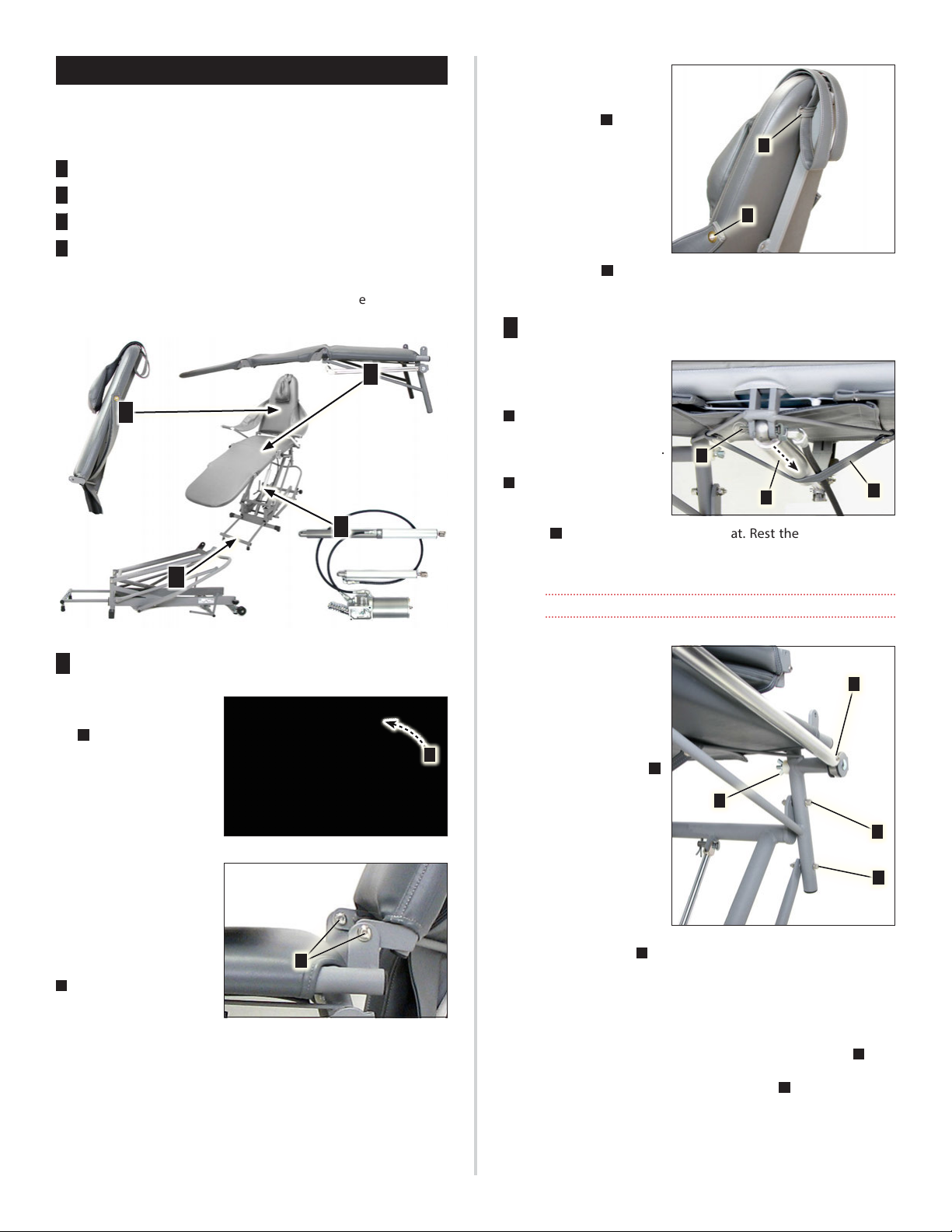
OVERVIEW: When disassembling the ADC‑02CF Chair, it is recom‑
mended that its modular components be detached and removed
in the following order:
1Backrest Assembly
2Seat Assembly
3Hydraulic Assembly (*)
4Base Assembly
(*) The individual components of the hydraulic assembly are not
customer‑serviceable and shouldn’t be disassembled in the eld.
Return to Aseptico if repairs are required.
1
2
3
4
1BACKREST ASSEMBLY
Disengage the backrest
latch [PN 462239] (Fig.
12 A) from the backrest
cylinder.
Use a 3/16” Allen wrench
and 1/2” combination
wrench to remove the bolts
[2x PN 510815], washers [4x
PN 510845], spacer wash‑
ers, [A/R PN 510297] and
nuts [2x PN 510126] (Fig. 13
A) that attach the backrest
assembly to the seat frame.
Note the quantities and po‑
sitions of the “A/R” (as required) spacer washers between the com‑
ponent frames. These washers should be used as spacers during re‑
assembly to ensure a snug t. Detach the backrest assembly and
set on workbench.
Use a Phillips screwdriver
to remove the pillow strap
mounting screws [2x PN
510239] (Fig. 14 A) that at‑
tach the pillow strap [PN
462313] to the rear of the
backrest. Remove strap
and pillow [PN 462304].
Use a 5/32” Allen wrench
to remove the screws
[PN 510841], washers [PN
510500] and bushings [PN
462301] (Fig. 14 B) that attach the arm slings [PN 462289] to the
sides of the backrest.
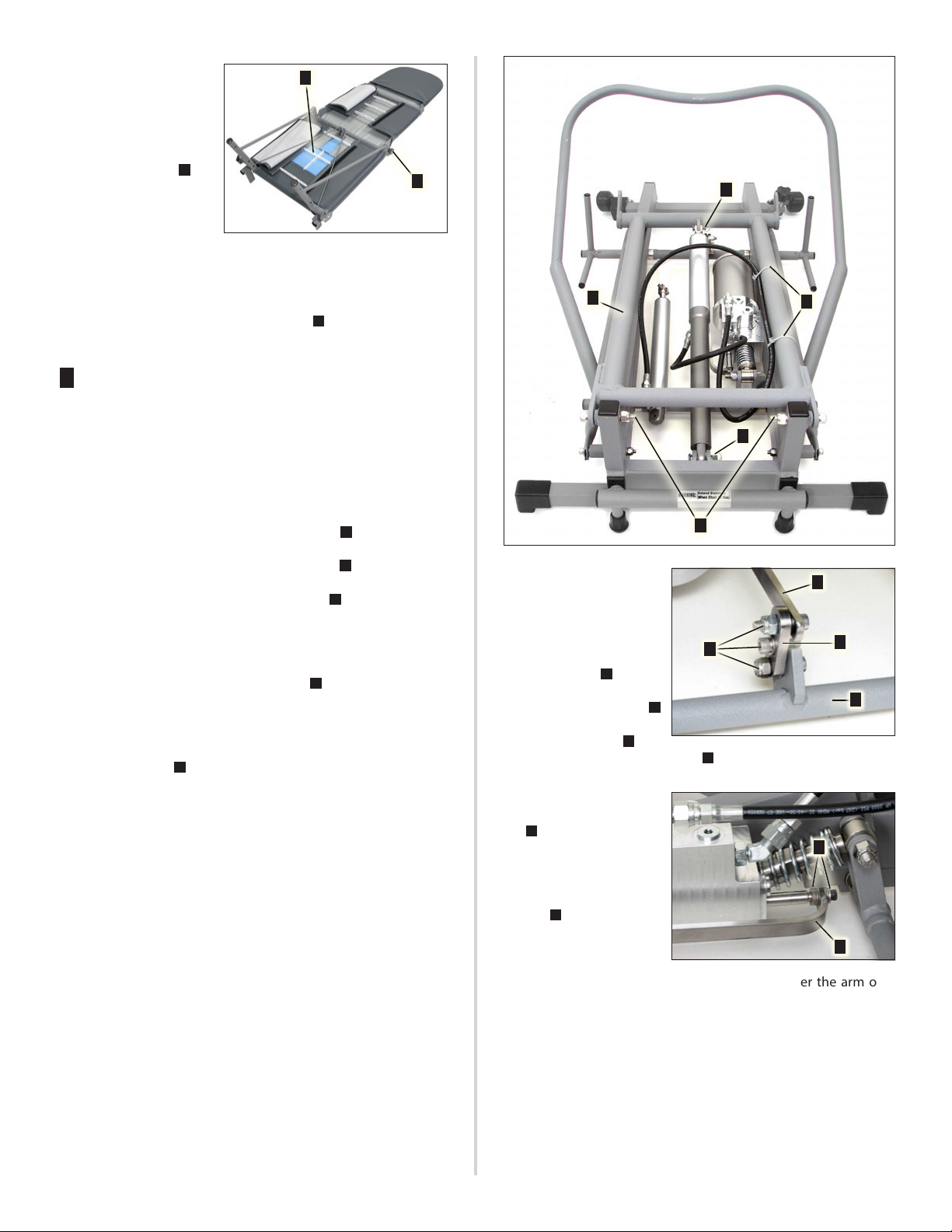
2SEAT ASSEMBLY
Remove the clevis pin
[PN 510917] and cotter
ring [PN 510927] (Fig. 15
A
) that attach the back‑
rest cylinder to the under‑
side of the seat assembly.
Push the cylinder (Fig. 15
B
) with attached hydrau‑
lic hose backward over the
support strap [PN 462291]
(Fig.15
C
) and out from under the seat. Rest the cylinder on the
oor until the complete hydraulic system can be detached as a
unit.
Do not disconnect the hydraulic hose from the cylinder.
Fold the foot and leg pan‑
els closed onto the seat
panel. Use a 3/16” Allen
wrench and 7/16” combina‑
tion wrench to remove the
bolts [2x PN 510842], wash‑
ers [6x PN 510500] and nuts
[2x PN 510296] (Fig. 16 A)
that attach the seat frame
to the base struts [2x PN
462191]. Note: One wash‑
er is installed between the
seat frame and each strut.
Use a 1/4” Allen wrench and
1/2” combination wrench
to remove the bolts [2x PN
510809], spacer washers [8x
(A/R) PN 510845] and nuts
[2x PN 510126] (Fig.16 B) that attach the seat frame to the main le‑
ver [PN 330614]. Note the quantities and positions of the A/R spacer
washers between the component frames; these washers should be
used as spacers during reassembly to ensure a snug t. Detach the
seat assembly and set on workbench. Remove the wing nuts [2x PN
510311], bolts [2x PN 510810], rubber washers [4x PN 710138], coved
washers [2x PN 510822] and washers [2x PN 510845] (Fig.16 C) that
attach the arm posts to the seat frame. Use an 1/8’’ Allen wrench
to remove the small screws [6x 510312] (Fig.16 D) that connect the
arm post components together.
A
Fig. 12Fig. 12
Fig. 13Fig. 13
A
Fig. 14Fig. 14
A
B
Fig. 15Fig. 15
B
A
C
Fig. 16Fig. 16
A
B
C
D

9
ADC-02CF
Unfold the leg and foot
panels then turn the seat
assembly over to expose
the underside. Peel back
the aps on the seat cover
and check the tie wraps [9x
PN 510135] (Fig. 17
A
) for
tightness. Replace tie wraps
as necessary. Because of its
vinyl covering, it is not rec‑
ommended that the chair’s
foot, leg, or seat panels be disassembled. However, if disassembly is
necessary, use a 5/32’’ Allen wrench and 7/16’’ combination wrench
to remove the foot panel mounting hardware and then use a 1/4’’
Allen wrench to remove the mounting screws [2 x PN 510048] and
adjustment knobs [2x PN 850025] (Fig. 17
B
) from the leg panel
framework.
3HYDRAULIC ASSEMBLY
IMPORTANT: When removing the hydraulic assembly, do not dis‑
connect any hydraulic lines nor open any hydraulic port connec‑
tions. The entire assembly can be detached from the chair as a
self‑contained system. If the integrity of this closed system is bro‑
ken, hydraulic oil may need to added and air may need to be bled
from the system.
Lower the main lever frame [PN 330614] (Fig. 18 A) down onto the
base frame by holding the selector lever in the SEAT LOWER posi‑
tion. Cut the two tie wraps [PN 510835] (Fig. 18 B) that attach the
hydraulic hose to the main lever frame. Remove the cotter ring
[PN 510927] and clevis pin [PN 510916] (Fig. 18 C) at the top end of
the seat cylinder where it connects to the main lever frame. Lower
this end of the cylinder down and rest it on the base until the oth‑
er end can be detached. Use a 5/16’’ Allen wrench and 9/16’’ com‑
bination wrench to remove the bolts [2x PN 510847], washers [A/R
PN 510846] and nuts [2x PN 510811] (Fig. 18 D) that attach the main
lever to the base. Note the quantities of the A/R washers between
the component frames. These washers should be used as spacers
during reassembly to assure a snug t. Remove the main lever and
place it aside. Remove the cotter ring [PN 510927] and the clevis pin
[PN 510917] (Fig. 18 E) from the lower end of the seat cylinder.
Fig. 18Fig. 18
AB
C
D
E
Use a 3/16’’ Allen wrench
and 7/16” combination
wrench to remove the bolts
[2x PN 510813], bolt [PN
510339], washers [2x PN
510500] and nuts [2x PN
510296] (Fig. 19 A) that at‑
tach the toggle selector
link [PN 462218] (Fig. 19 B)
to the linkage selector arm
[PN 462249] (Fig. 19 C) and
selector lever [PN 330625] (Fig. 19 D).
At the opposite end of the
linkage selector arm (Fig.
20
A
), where it attaches
to the pump, use a 5/32’’
Allen wrench to remove
the bolt [PN 510119] and
washers [A/R PN 510500]
(Fig. 20
B
). Note that when
reassembling these com‑
ponents, these A/R wash‑
ers should be spaced on
each side of the selector arm as required to center the arm over
the selector lever at the opposite end.
Fig. 17Fig. 17 A
B
Fig. 19Fig. 19
B
C
D
A
Fig. 20Fig. 20
B
A

10
ADC-02CF
Use a 3/16’’ Allen wrench
to remove the bolts [2x PN
510692] and washers [2x PN
510500] (Fig. 21 A) that at‑
tach the pump mount sti‑
ener [PN 462259] (Fig. 21 B)
and pump (Fig. 21 C) to the
base frame. Remove the
hydraulic pump, two cyl‑
inders and two hoses that
comprise the entire hy‑
draulic assembly without disconnecting any hydraulic components
nor opening any hydraulic ports.
Disassembly of the hydraulic assembly is not recommended
unless a component malfunctions. Refer to the Schematic
Drawings (page 14) for conguration details.
4BASE ASSEMBLY
Disassembly of the ADC‑02CF base is not necessary unless a com‑
ponent breaks. If disassembly is required, remove the primary com‑
ponents as follows:
Use a 5/16’’ Allen wrench and 9/16’’ combination wrench to remove
the bolt [PN 510812], roller [PN 462233], bushing [PN 520105] and
nut [PN 510811] (Fig. 21 D) from the lift lever.
Use a 3/16’’ Allen wrench
to remove the bolts [4x PN
510813] that attach the le‑
ver mounting brackets [2x
PN 462243] (Fig. 22
A
) to
the base frame. When re‑
moving the lift lever (Fig.
22
B
), note the bearing
pins [PN 510818] mounted
inside each of the mating brackets (Fig. 22
C
).
Remove the selector ped‑
als [2x PN 330636] (Fig.
23
A
) on each side of the
chair by depressing the
locking buttons and pull‑
ing the selector pedals out
of selector lever bar (Fig.
23
B
). Use a 3/16’’ Allen
wrench to remove the
bolts [4x PN 510813] that attach the pump switch brackets [2x PN
462242] (Fig. 23
C
) to the base frame. Use a 3/32” Allen wrench to
remove the bearing screws [2x PN 510857]. Remove the selector
lever bar [PN 330625] with bearings [2x PN 462511].
Use two 1/2” combination
wrenches to remove the
bolts [2x PN 510806], bear‑
ings [4x PN 520115], spacers
[2x PN 510823] and nuts [2x
PN 510126] that attach the
wheels [2x PN 730679] (Fig.
24 A) to their struts.
The knob [PN 850042] and leveling foot [PN 850044] (Fig. 24
B
) and
the rubber feet [2x PN 462312 & 1x PN 462390] do not require disas‑
sembly or maintenance and can be left attached to the frame.
THIS COMPLETES THE DISASSEMBLY PROCEDURE FOR THE
CHAIR.
REASSEMBLY:
To reassemble the chair, follow the above instructions in the re‑
verse order.
Refer to the Schematic Drawings (page 14) for part numbers
and conguration drawings when reassembling chair.
Fig. 21Fig. 21
B
D
A
C
Fig. 22Fig. 22 A
C
B
Fig. 23Fig. 23
A
C
B
Fig. 24Fig. 24
A
B
DISASSEMBLY (Continued)

11
ADC-02CF
REPACKING THE CHAIR
1. ARM SLINGS: Remove the arm
slings from the ends of the arm
posts, then tuck the arm slings
into the frame on the rear of
the backrest.
2. ARM POSTS: Rotate the arm
posts down just below the seat
frame, then fold in the hand
grips (Fig. 25 A).
Make sure the hand grips are
positioned below the seat
frame before proceeding or damage to the upholstery may
occur when folding the leg and foot panels closed.
3. FOAM & PANELS: Place a
piece of foam (Fig. 26 A) over‑
lapping the seat and backrest
panels. Tie two small pieces
of foam (Fig. 26 B) around the
arm post pivots. Fold the foot
and leg panels closed onto
the seat panel.
4. BACKREST PANEL: Flip the
pillow (Fig. 27 A) over to the
rear side of the backrest.
Detach the backrest latch
from the cylinder, then fold
the backrest down onto the
seat panel.
5. LOWER CHAIR: Press and hold the selector lever in the SEAT
LOWER position until the seat frame touches the oor. If the
seat frame won’t lower all the way, press down on the lift lever
and hold it there while simultaneously holding the selector
lever in the SEAT LOWER position.
6. SELECTOR LEVERS: If the selector levers are in the extended
position, retract each one by pushing in on the locking button,
then sliding the selector lever in until the locking button pops
out of the inner hole on the selector lever tube.
7. BACKREST STRAP: Tuck the
pillow down between the
chair framework. Guide the
backrest strap (Fig. 28 A)
under the main lever frame
and over the top of the back‑
rest, then fasten the strap
securely.
8. STABILIZER BAR: Fully
retract the stabilizer bar.
9. LOADING CASE: Using two
people, lift the chair and
place it into the transport
case. Make sure to position
the headrest end (Fig. 29
A
)
of the chair towards the label
(Fig. 29
B
) inside the case to
prevent the chair from get‑
ting scratched by the rivets on the inside of the case.
10. LOCKING CASE: Place the lid
on the case and close all 10
latches (Fig. 30
A
). The case
is equipped with wheels for
easy transport.
• ALWAYS LIFT THE CASE USING THE HANDLES PROVIDED.• ALWAYS LIFT THE CASE USING THE HANDLES PROVIDED.
• WHEN TRANSPORTING CHAIR, DO NOT PLACE HEAVY OBJECTS ON• WHEN TRANSPORTING CHAIR, DO NOT PLACE HEAVY OBJECTS ON
TOP OF THE CASE.TOP OF THE CASE.
CAUTION
Fig. 25Fig. 25
A
Fig. 26Fig. 26 A
B
Fig. 27Fig. 27 A
Fig. 28Fig. 28
A
Fig. 29Fig. 29
B
A
Fig. 30Fig. 30
A

12
ADC-02CF
SPECIFICATIONS
Chair Dimensions:
Chair, Folded . . . . . . . . . . . . . . . . . . 34’’L x 22’’W x 18’’H (86.4 x 55.9 x 45.7 cm)
Chair, Extended . . . . . . . . . . . . . . . . . 76’’L x 24’’W x 36’’H (193 x 60.9 x 91.4 cm)
Range of Chair Positions:
Minimum Seat Height . . . . . . . . . . . . . . . . . . . . . . . . . . . . . . .11’’ (27.9 cm)
Maximum Seat Height . . . . . . . . . . . . . . . . . . . . . . . . . . . . . . 33’’ (83.8 cm)
Backrest Adjustable from upright (vertical) to supine (horizontal) positions
Chair Weight:
Chair only . . . . . . . . . . . . . . . . . . . . . . . . . . . . . . . . . . . . . .69 lb (31.3 kg)
Maximum Load Capacity . . . . . . . . . . . . . . . . . . . . . . . Approx. 300 lb (136 kg)
Shipping Case Dimensions:
Case Size . . . . . . . . . . . . . . . . . . 25’’ W x 38’’ L x 24’’ H (64 cm x 97 cm x 61 cm)
Shipping Case Weight:
Case only . . . . . . . . . . . . . . . . . . . . . . . . . . . . . . . . . . . . . 51.5 lb (23.4 kg)
Fully Loaded . . . . . . . . . . . . . . . . . . . . . . . . . . . . . . Approx. 121 lb (54.9 kg)
Hydraulic Oil:
Industrial premium-quality, medium-grade oil (ISO VG 46, SAE 15), such as Mobil DTE
25 or equivalent.
SYMBOL DEFINITIONS
WARNING – Serious damage, injury or death may result
if ignored.
CAUTION – Damage to property, the environment or
injury may result if ignored.
Manufacturer
Serial number
Do not sit on leg panel or foot panel.
Information – Useful tips or hints.
Authorized European Representative
REQUIRED TOOLS LIST
Allen Wrenches:
3/32”
1/8”
5/32”
3/16”
1/4”
5/16’’
Combination Wrenches (or Socket Wrenches):
7/16”
1/2”
9/16”
5/8”
Screwdrivers:
#2 Phillips
3/8” Flathead
Pliers:
Standard

13
ADC-02CF
TROUBLESHOOTING GUIDE
Seat or backrest locks up and cannot be raised or lowered:
• Refer to Clearing Hydraulic Lockups on page 4.
When preparing the chair for shipping, the frame posts
won’t lower all the way to the oor:
• Press down and hold the selector lever in the SEAT LOWER
position and press and hold down the lift lever simultaneously.
Chair’s hydraulics feel sluggish or jerky when raising or
lowering the seat or backrest:
• Refer to Purging Air from the Hydraulic System on page 5.
• Refer to Adding Oil to the Hydraulic System on page 7.
Oil is leaking from the hydraulic system:
• NOTE: Small amounts of oil leaking after prolonged use are
normal.
• Tighten all hydraulic hose ttings and port plugs on the
hydraulic pump. If leakage persists, contact Aseptico custom‑
er service about returning the hydraulic assembly for repairs.
WARRANTY
Aseptico warrants this product against defects in material or work‑
manship for a period of two (2) years, from date of original invoice.
Aseptico’s sole obligation under product warranty is (at its sole op‑
tion and discretion) to repair or replace any defective component
or product in part or whole. Aseptico shall be the sole arbiter of
such action.
In the event of alleged defect under warranty, the purchaser
is to notify Aseptico’s customer service department promptly.
Customer service will provide instructions, usually directing that
the product be returned for service. Shipment to Aseptico and the
cost thereof is always the responsibility of the purchaser.
Accidental misuse, inappropriate installation, or failure to perform
directed maintenance voids the warranty. Deliberately defacing,
modifying, or removing the serial number voids the warranty.
Aseptico does not assume, under this warranty, any risks or liabili‑
ties arising from the clinical use of its products, whether or not such
use involves coincidental utilization of products manufactured by
others.
REPAIRS
Aseptico repairs carry a ninety (90) day limited warranty against
defects in material and workmanship. This warranty pertains only
to the specic repair. Any new and dierent defect in materials or
workmanship will be treated as a new repair. If the product is not
covered under warranty, Aseptico oers repair services for a fee.

14
ADC-02CF

15
ADC-02CF

P.O. Box 1548 • Woodinville, WA 98072‑1548
(800) 426‑5913 • (425) 487‑3157
www.aseptico.com • info@aseptico.com
P/N: 421020 • Rev. I • ECO 14925 • 02/2020 • Printed in the USA
Other manuals for ADC-02CF
1
Table of contents
Other Aseptico Indoor Furnishing manuals
Popular Indoor Furnishing manuals by other brands

Pine Crafter Furniture
Pine Crafter Furniture 3012 instructions

DHP
DHP 3265098 manual

Rapid Racking
Rapid Racking Rapid silver workbench Assembly guide

Crosley
Crosley AC1052A instruction manual

Next
Next FORESTER NEST 803376 Assembly instructions

Cooper Lighting
Cooper Lighting NEO-RAY 82 Specification sheet

Cosco
Cosco 5850207PCOM manual

Trendteam
Trendteam LINE 866 Series installation instructions

Mr. Christmas
Mr. Christmas Christmas Cable Cars manual

Hooker Furniture
Hooker Furniture 5751-10459-99 Assembly instruction

Branch
Branch Double Standing Desk Assembly guide

Winners Only
Winners Only DCT35624G Assembly instructions