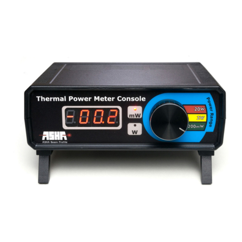
ASHA PMB-101 User manual

Cover
ASHA Beam Prole
PhotodiodePowerMeterBundle
PMB-101

WWW.ASHA-CO.IR2
About Us
In order to design and manufacture programmable optometrical, op-
tomechanical and optoelectronical devices, the science-based compa-
ny, ASHA Beam Prole, was established in 2016.
ASHA has been able to design a wide range of devices, relying on
indigenous capability and knowledge. Also, since being calibratable is
essenal for measuring equipment, clients can carry out their period-
ical calibraon.
Field of activity
The main eld of acvity of this company is the design and produc-
on of laser, opcs and photonics equipment and can be categorized
in the following topics:
»Diode laser driver
»Laser diode stabilizer
»Laser Parameters measuring equipment such as Power Meter, Beam Pro-
ler, and Ultra-fast Detector
»Lithographic masks
»Linear posioner with stepper motor driver
»Calibraon of Power Meters and beam prolers
»Design and producon of soware to facilitate the use of electro-opc
and optomechanical programmable equipment

3WWW.ASHA-CO.IR
Main features
Introduction
Measuring the output of light sources is very important. For exam-
ple, the opcal power of medical lasers is very sensive and can cause
irreparable damage if the funcon of the device goes out of its proper
range. In experimental and research applicaons, it is always neces-
sary to measure the output of laser sources. In addion to the above,
it is crucial to pay special aenon to the necessity of calibraon of
industrial and military laser equipment.
Hence, the semiconductor power meter is designed for high preci-
sion laser applicaons. Producons of this company can well meet the
needs of the scienc and industrial community in the eld of power
metering.
The semiconductor power meter is designed for high precision laser
applicaons. The products of this company can well meet the needs of
the scienc and industrial community in the eld of power metering.

WWW.ASHA-CO.IR4
Features
»Direct connecon to the mulmeter with a special cable (depends on
order)
»Ability to operate in 12 dierent wavelengths from 350 nm to 1100 nm
(depends on order)
»Adjustable for desired light sources in the specied wavelength range
(depends on order)
»Able to have specic Gain for required scale (depends on order)
»Measuring the power of coherent opcal sources
»Measuring the power of connuous light sources
»Possibility to remove background radiaon and photodiode dark current
(depends on order)
»Internal rechargeable baery for portable use
Applications
»Study incident and reected beam power and qualify light sources
»Study the eect of environmental changes on laser sources performance
»Study the variaon of power when passing through (transparent) envi-
ronments
»Examining the quality of lenses and opcal windows
»Measure the intensity of reecon/passing beam from dierent surfaces
Warning! With regard to the items listed in the requirements secon,
to maximize the accuracy of the device, it is strongly recommended to
connect the power meter earth to the standard one.

5WWW.ASHA-CO.IR
Technical Features
Item Min Typ Max Unit
Input Voltage 4.75 5 5.25 V
Input Current 60 250 500 mA
Baery -<2000 - mAh
Baery Life -20 - h
Charge Time - 5- h
Wavelength Range 355 -1064 nm
Opcal Power Working Range*0.01 -240 mW
Display Power Range 0.1 -199.9 mW
Measurable Wavelengths** 355, 405, 450, 532, 633, 650, 780, 808, 850, 970, 1064 nm
Measurement Uncertainty ±5 %
* Measuring power in the range of 10 mW to 240 mW is possible If
connect 5.5 digit voltmeter with 1 uV accuracy to output.
** Maximum FWHM for console display should be ±5 nm and for
voltmeter output should be ±1nm.
Note Console output voltage is equal to one-tenth of opcal source power. So
1 V in output is equal to 100 mW power of the opcal source.

WWW.ASHA-CO.IR6
More Spec. Discripon
Dimenon Detector 35x35x18.5 mm3
Console 180x165x70 mm3
Weight Detector < 200 gr
Console < 1000 gr
Detector Connecon DB9
Output Connecon BNC
Acve Detector Area 10x10 mm2
Input Aperture Ø9 mm
Display 2000 counts - 7segment
Figure1.Ph o to d i o d e P owe r M ete r S en so r wi th A n nu l ar U V V i ewi n g Ta rg e t

7WWW.ASHA-CO.IR
Figure2.PhotodiodePowerMeterConsole-FrontView
Figure3.PhotodiodePowerMeter-BackView

WWW.ASHA-CO.IR8
Contents
About Us ............................................................................ 2
Field of acvity 2
Main features..................................................................... 3
Introducon 3
Features 4
Applicaons 4
Technical Feature 5
Power Meter Parts ............................................................. 9
Packaging Content 9
Detector Parts 10
Console Parts 11
Setup................................................................................ 13
Safety 13
Preparaon and measurement 14
Requirements 16

9WWW.ASHA-CO.IR
Power Meter Parts
Available Accessories
Please make sure that all accessories are available for the box in your
rst use.
»Photodiode Sensor x 1
»Dust Cap x 1
»Photodiode Power Meter Console x 1
»User Manual* x 1
»5V Power Supply x 1
»Mulmeter Connector Cable x 1
»M4 Screw x 2
* Digital version of this user manual is available by scanning the QR-
code under the console.

WWW.ASHA-CO.IR10
Detector Parts
Figure4. SemiconductorPowerMeterSensor-FrontView
1. M4 screw for vercal aligning
2. Sensor Cap(if open, guarantee void)
3. Visible spectrum detector (depends on order)
4. Connector cable
5. M4 screw
6. Input aperture(Opcal Filter)
7. Cap furrow
8. Anodised Aluminum body

11 WWW.ASHA-CO.IR
Figure5.Frontpartsofphotodiodepowermeterconsole
1. Wavelength selector 2. 4 digits display for reporng power
3. ON/OFF Key & Baery status LED
4. Input Power
5. Detector connector
6. Oset null volume(depends on
order)
7. Output (BNC)
8. To download datasheet
scan this QRcode
Figure6. Backpartsofphotodiodepowermeterconsole
Console Parts

WWW.ASHA-CO.IR12
Pinout
Figure7.PhotodiodeSensorPinout

13 WWW.ASHA-CO.IR
Setup
Safety
It should be noted that all safety ps in this manual are only use-
ful when used in accordance with the condions and for use un-
der the menoned situaons. All parts should be connected to
each other with a suitable and shielded cable. If you need to re-
place some parts of Asha’s company with others, you need to in-
form ASHA’s Technical support. If any changes in the compo-
nents of the product are applied, it may lose its funconality.
Due to the body reecon and opcal lter, it is recommend-
ed that you turn o the light source or set it in low pow-
er mode when using in the desired locaon. It is also nec-
essary to have an orthogonal beam on the sensor surface.
This instrumentaonal device only will be calibrated when placed in
the foam and special box according to the original packaging. It is rec-
ommended that you take alternave packaging from ASHA company
if necessary.

WWW.ASHA-CO.IR14
Preparation and Measurement
To set up the device, rst it is necessary to put the sensor perpen-
dicular to the beam axis with the proper connecon at the desired
locaon, and then connect the sensor cable to the device.
The device has a display on its front panel, and it’s possible to directly
display the result on the screen in addion to measuring through the
mulmeter. The output of this device, according to the order, is able
to be calibrated for required wavelengths, so that the output voltage
of the device reports the exact amount of beam power.
If you want to measure power using a voltmeter, using the supplied
cable, connect the analog output of the device (BNC port) to the cor-
responding BNC cable, then connect the black probe to the COM port
and the red probe to the voltmeter. Then turn on the device by using
the On/O key. If the device has enough baery, the display on the
front panel of the console will turn on. Otherwise, connect the adapter
to the input power connector. In this case, the red light turns on on the
on/o key, which means that the baery is charging and you can use
the console at the same me. When the baery is fully charged, the
red light will turn o and you can unplug the adaptor from the console.
This device can measure 12 wavelengths specied in the techni-
cal table. To prepare the device to measure the desired wavelength,
turn the selector and select the desired wavelength. For the user’s
convenience, the wavelengths of the device with the corresponding
approximate color are indicated symbolically on the front panel. Ob-

15 WWW.ASHA-CO.IR
viously, the incorrect wavelength selecon results in wrong reports.
In the end, turn on the beam source or remove the obstacle and mea-
sure the beam.
One of the features of this product (according to the order)is the oset
seng, which can be used to remove the background radiaon and
then measure the absolute power of the beam source. To do this, use
the oset knob on the back panel of the device and rotate the knob
to apply the desired oset according to the applicaon. One of the
important applicaons of this feature is the removal of the background
radiaon from the end result, which is very useful in environments
with unwanted background radiaon.

WWW.ASHA-CO.IR16
Requirements
»High precision analog or digital voltmeter (5.5Digits)
»Appropriate Power Supply (Available in Package)
»Standard ground connecon (Due to the high sensivity of
the sensor, if there is no proper ground connecon, the envi-
ronmental noise will greatly aect the sensor performance.)
It is necessary to menon that this power meter is very precise and sen-
sive and due to the precision the device output (listed in the table),
in order to use full capabilies of the device, it is recommended to use
voltmeters with the accuracy beer than 100μV.

17 WWW.ASHA-CO.IR
Drawings
Figure8. PhotodiodePowerMeterConsoleDimensions

WWW.ASHA-CO.IR18
Figure9.PhotodiodePowerMeterDetectorDimensions

19 WWW.ASHA-CO.IR
Thispageisleblankintenonally.

Back
Table of contents
Other ASHA Measuring Instrument manuals
Popular Measuring Instrument manuals by other brands

Precision Digital Corporation
Precision Digital Corporation ProtEX-MAX PD8-6100 instruction manual

Bushnell
Bushnell Tour V2 201930 user manual

Bender
Bender ISOMETER isoHV425 operating manual

Armada
Armada Pro30 operating manual

Hanna Instruments
Hanna Instruments HI97734 instruction manual

Interlogix
Interlogix TVN 2264P Guidelines