manuals.online logo
Brands
  1. Home
  2. •
  3. Brands
  4. •
  5. PASCO
  6. •
  7. Measuring Instrument
  8. •
  9. PASCO EM-3556 User manual

PASCO EM-3556 User manual

Product Manual
012-16529B
800-772-8700 www.pasco.com
Modular Circuits Advanced Expansion Kit
EM-3556
Included Equipment
Item
Qty
1
Gratnells Case with foam, tray, and lid
1
2
Speaker Module
1
3
DC Buzzer Module
1
4
Diode Module
1
5
Solar Cell Module
1
6
MOSFET Module
1
7
Two Terminal Module
1
8
Bipolar Junction Transistor Module
1
9
Jumper Clips
15
10
Transistors:
2
2
2
N-channel MOSFET (2N7000-TA)
P-channel MOSFET (TP2104)
NPN Bipolar Junction Transistor (2N3904-TFR)
PNP Bipolar Junction Transistor (2N4403-AP)2
*Included with the EM-3555 Modular Circuits AC/DC Advanced Expansion Kit
Recommended Equipment
The following table lists the equipment required to perform
experiments with the kit. At least one of the options
provided for each item is recommended.
Item
Options
Modular
Circuits Set
EM-3535 Basic Kit
EM-3536 Essential Physics Kit
Function
Generator
EM-3533 Wireless AC/DC Module
*
EM-3556 Modular Circuits Advanced Expansion Kit
012-16529B
Module Descriptions
DC Buzzer
The DC buzzer module produces sound when a DC
voltage is applied to the terminals. The buzzer is polarized
and will only produce a sound when a positive voltage is
applied to the positive terminal. When 2-3 V is applied, the
buzzer will produce a sound with a frequency of
2300 ± 400 Hz.
Speaker
The speaker module produces sound when an AC voltage
is applied to the terminals. The frequency of sound
produced is determined by the frequency of the AC
waveform. The speaker has an 8 Ωimpedance and is
connected in series with a 10 Ω resistor for protection.
Diode
The diode module contains a PN junction diode that
allows current to flow in only one direction. Current will
flow when a negative voltage is applied to the side of the
diode marked with the grey ring. The arrow on the diode
symbol indicates the direction of conventional current.
Solar Cell
The solar cell module outputs a voltage when light shines
on the solar cell. The solar cell works best when using the
sun or an incandescent lamp as a light source. The solar
cell has a rated voltage of 5 V and a rated current of
90 mA.
NOTE
•Do not place an incandescent bulb too close to
the solar cell as it is possible to melt the case.
•
Do not connect the solar cell to a power
source. This will permanently damage the
solar cell making it non-functional.
EM-3556 Modular Circuits Advanced Expansion Kit
012-16529B
Two Terminal
The two terminal module allows an external power supply
or signal generator to be used as a voltage source. The
module contains a fuse that will trip when the output
current is greater than 2 A. The fuse will automatically
reset after a few seconds.
NOTE
The fuse only provides overcurrent protection. It does
not provide overvoltage protection. Set the voltage limit
of your power supply to 3 V to prevent damage to the
Modular Circuits components.
Bipolar Junction Transistor
The Bipolar Junction Transistor (BJT) module contains a
3-pin connector to insert a BJT transistor. The module
identifies the location of the emitter (E), base (B), and
collector (C) pins and which direction the flat side of the
transistor faces.
The kit includes two NPN (2N3904) and two PNP
(2N4403) BJT transistors, though any standard transistor
can be used with the module. Make sure to check the
pinouts on the datasheet when using other transistors.
MOSFET
The MOSFET module contains a 3-pin connector to insert
a MOSFET. The module identifies the location of the
source (S), gate (G), and drain (D) pins and which
direction the flat side of the MOSFET faces.
The kit includes two N-channel (2N7000) and two
P-channel (TP2104) MOSFETs. Any standard MOSFET
can be used with the module. Make sure to check the
pinouts on the datasheet when using other MOSFETs.
Experimental Setup
To connect to a module
Connecting a module to other modules requires a
physical and electrical connection (Figure 1):
1. Physically connect the module by slipping the peg
and notch on one edge of the module onto the
notch and peg of another module.
2. Electrically connect the module by inserting a
jumper clip into the clip holders.
Figure 1. Wireless AC/DC Module connected to a wire module
with a jumper clip inserted.
EM-3556 Modular Circuits Advanced Expansion Kit
012-16529B
Technical Support
For assistance with PASCO products, contact PASCO
Technical Support at:
Address: PASCO scientific
10101 Foothills Blvd.
Roseville, CA 95747-7100
Phone:
916-462-8384
Web:
www.pasco.com
Email:
support@pasco.com
FCC Statement
This digital device complies with part 15 of the FCC Rules.
Operation is subject to the following two conditions: (1) This
device may not cause harmful interference, and (2) this device
must accept any interference received, including interference
that may cause undesired operation.
Product End of Life Disposal Instructions
This electronic product is subject to disposal and recycling
regulations that vary by country and region. It is your
responsibility to recycle your electronic equipment per your local
environmental laws and regulations to ensure that it will be
recycled in a manner that protects human health and the
environment. To find out where you can drop off your waste
equipment for recycling, please contact your local waste
recycle/disposal service, or the place where you purchased the
product.
The European Union WEEE (Waste Electronic and
Electrical Equipment) symbol (to the right) and on the
product or its packaging indicates that this product
must not be disposed of in a standard waste
container.
Warranty, Copyright, and Trademarks
Limited Warranty For a description of the product warranty, see
the PASCO catalog.
Copyright This document is copyrighted with all rights reserved.
Permission is granted to non-profit educational institutions for
reproduction of any part of this manual, providing the
reproductions are used only in their laboratories and
classrooms, and are not sold for profit. Reproduction under any
other circumstances, without the written consent of PASCO
scientific, is prohibited.
Trademarks PASCO and PASCO scientific are trademarks or
registered trademarks of PASCO scientific, in the United States
and/or in other countries. All other brands, products, or service
names are or may be trademarks or service marks of, and are
used to identify, products or services of, their respective owners.
For more information visit www.pasco.com/legal.
Other PASCO Measuring Instrument manuals

PASCO PS-3321 User manual

PASCO

PASCO PS-3321 User manual

PASCO TD-8513 User manual

PASCO

PASCO TD-8513 User manual

PASCO SF-9568A User manual

PASCO

PASCO SF-9568A User manual

PASCO PS-3238 User manual

PASCO

PASCO PS-3238 User manual

PASCO PS-3230 User manual

PASCO

PASCO PS-3230 User manual

PASCO SF-9568A User manual

PASCO

PASCO SF-9568A User manual

PASCO PASPORT PS-2174 User manual

PASCO

PASCO PASPORT PS-2174 User manual

PASCO ES-9078A User manual

PASCO

PASCO ES-9078A User manual

PASCO OS-8525A User manual

PASCO

PASCO OS-8525A User manual

PASCO PS-2600 Use and care manual

PASCO

PASCO PS-2600 Use and care manual

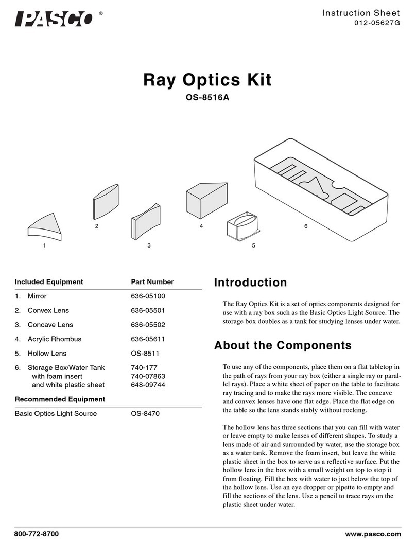
PASCO OS-8516A User manual

PASCO

PASCO OS-8516A User manual

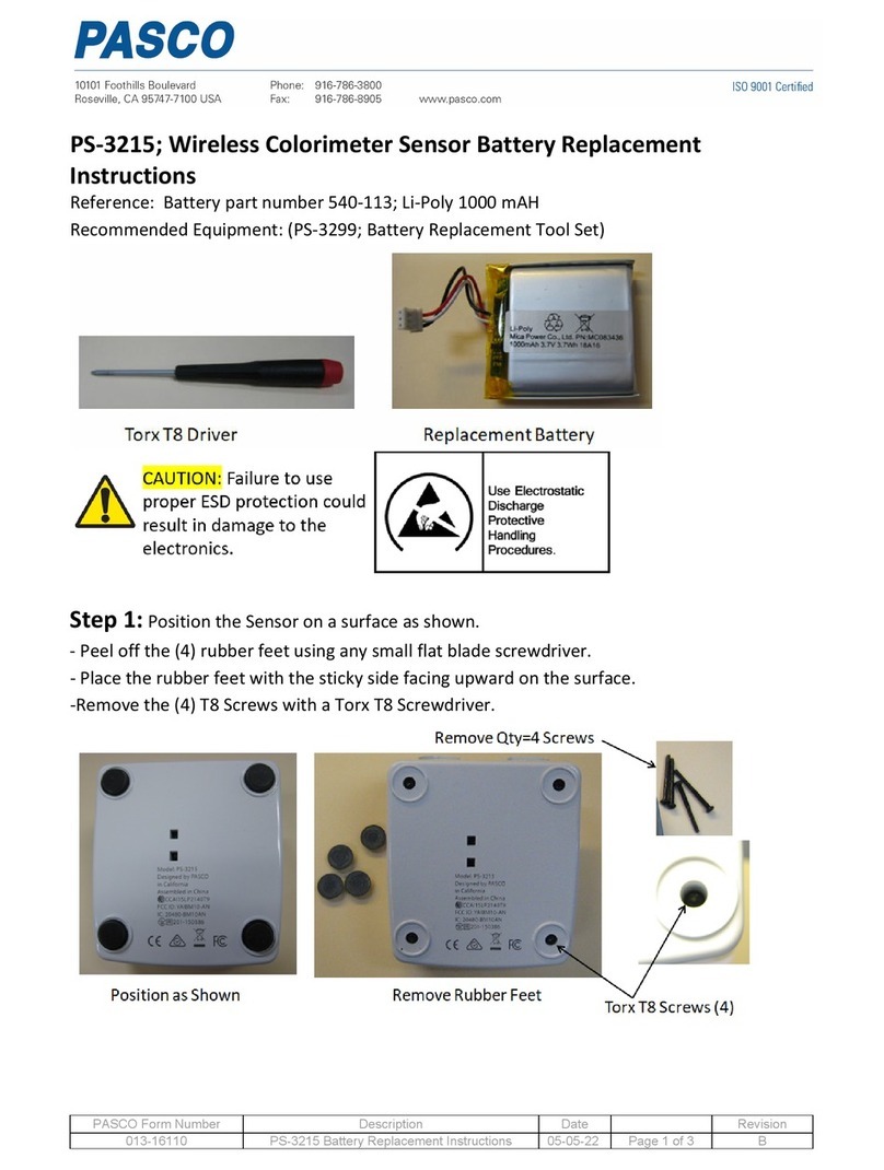
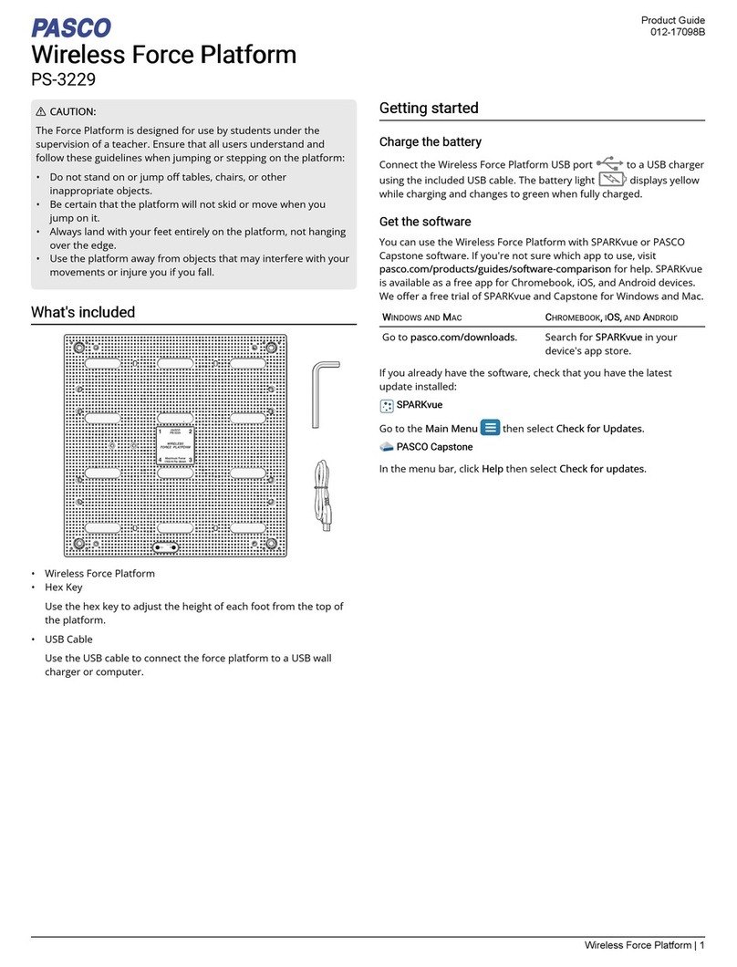
PASCO PS-3229 User manual

PASCO

PASCO PS-3229 User manual

PASCO PS-3223 User manual

PASCO

PASCO PS-3223 User manual

PASCO WA-7428 User manual

PASCO

PASCO WA-7428 User manual

PASCO SP-9285 User manual

PASCO

PASCO SP-9285 User manual

PASCO PS-3216 User manual

PASCO

PASCO PS-3216 User manual

PASCO Pasport PS-2152 User manual

PASCO

PASCO Pasport PS-2152 User manual

PASCO OS-7053 User manual

PASCO

PASCO OS-7053 User manual

PASCO ME-9495A User manual

PASCO

PASCO ME-9495A User manual

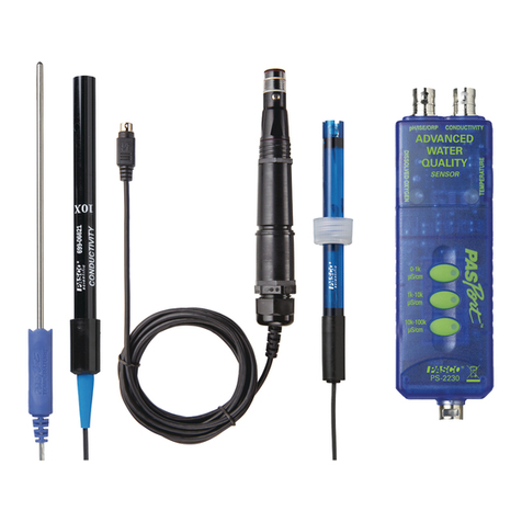
PASCO PASPORT PS-2230 User manual

PASCO

PASCO PASPORT PS-2230 User manual

PASCO PS-3515 User manual

PASCO

PASCO PS-3515 User manual

PASCO PASPORT PS-2108 User manual

PASCO

PASCO PASPORT PS-2108 User manual

PASCO PS-3518 User manual

PASCO

PASCO PS-3518 User manual

PASCO SF-9500A User manual

PASCO

PASCO SF-9500A User manual

Popular Measuring Instrument manuals by other brands

DeFelsko PosiTector 6000 Reference

DeFelsko

DeFelsko PosiTector 6000 Reference

TTI PFM3000 instruction manual

TTI

TTI PFM3000 instruction manual

IGM MULTIGASSENS-M2 user manual

IGM

IGM MULTIGASSENS-M2 user manual

Flexitron webdyn MTX-StarEnergy-E Software user manual

Flexitron

Flexitron webdyn MTX-StarEnergy-E Software user manual

Claas ba-1381 Operation instructions

Claas

Claas ba-1381 Operation instructions

Tektronix TLA7012 instructions

Tektronix

Tektronix TLA7012 instructions

Xylem Sensus PolluTherm F Installation and operating instructions

Xylem

Xylem Sensus PolluTherm F Installation and operating instructions

Mezon DSTM500 user manual

Mezon

Mezon DSTM500 user manual

Agu Skinny user manual

Agu

Agu Skinny user manual

Hanna Instruments HI702 instruction manual

Hanna Instruments

Hanna Instruments HI702 instruction manual

P3 International P0320 Operation manual

P3 International

P3 International P0320 Operation manual

MSA altair 4 Service manual

MSA

MSA altair 4 Service manual

ScienTECH Vector Series operating manual

ScienTECH

ScienTECH Vector Series operating manual

LANDTEC BIOGAS 3000 operating manual

LANDTEC

LANDTEC BIOGAS 3000 operating manual

Panasonic DMRE20 - DVD VIDEO RECORDER operating instructions

Panasonic

Panasonic DMRE20 - DVD VIDEO RECORDER operating instructions

B-I Inductrial BI-SM2004 manual

B-I Inductrial

B-I Inductrial BI-SM2004 manual

HEIDENHAIN ND 282 Instruction

HEIDENHAIN

HEIDENHAIN ND 282 Instruction

Radiodetection 6100-Gfast Operation manual

Radiodetection

Radiodetection 6100-Gfast Operation manual

manuals.online logo
manuals.online logoBrands
  • About & Mission
  • Contact us
  • Privacy Policy
  • Terms and Conditions

Copyright 2025 Manuals.Online. All Rights Reserved.