Leutert MSI-3 User manual

Cylinder Pressure
Monitoring
Digital Pressure Indicator DPI
•No installation
•Ready to use
•High quality sensor
•Large memory
•Easy handling
•Cost effective
+49-4131-959-0 | sales.maritime@leutert.com
.com
Peak Pressure Indicator MSI-3
Operating Instructions
Engine Indicator
The Leutert Peak Pressure Indicator MSI-3 measures and
displays maximum compression or ignition pressures in
individual cylinders of large two- or four-stroke engines.

Friedrich Leutert GmbH & Co. KG MSI-3 Operating Instructions, Page 2
EC-Declaration of Conformity
The Manufacturer
Friedrich Leutert GmbH & Co. KG
Schillerstrasse 14, 21365 Adendorf, Germany
declares that the following product:
Product Peak Pressure Indicator MSI-3
£160 bar Part-No. 4644.00.00000
£250 bar Part-No. 4645.00.00000
Max. working pressure £300 bar Part-No. 4646.00.00000
Permissible temperature ambient -20 to 60°C
meets the regulations of the following directives including their alterations being valid at the time
of this declarations:
¨Machinery Directive 2006/42/EG
¨Pressure Equipment Directive 2014/68/EU (PED), Modul A
Adendorf, 01.12.2019
place,date Representative of executive management for declarations of conformity

Friedrich Leutert GmbH & Co. KG MSI-3 Operating Instructions, Page 3
Introduction
This operating manual provides instructions on how to use this product correctly, effectively
and safely for the intended purpose. Please read all instructions, notes on danger and warning
attentively. Please follow all safety instructions and precautionary notes in order to avoid damage
to people or property during operation. LEUTERT can not be held responsible for damage or
injury resulting from improper product use, incorrect operation or lack of maintenance.
This operating manual is directed to technically trained personnel. In case of doubt regarding
safety or operational aspects, please do not hesitate to contact LEUTERT for assistance. Should
you notice a faulty description or depiction or if you would like to suggest points for improvement,
we are looking forward to hearing from you.
Please keep the operating manual near the product to have it available if needed. Make sure that
the manual is protected from dirt and moisture.
Explanation of symbols:
DANGER
indicates a hazardous situation which, if not avoided, will result in death or serious injury.
WARNING
indicates a hazardous situation which, if not avoided, could result in death or serious injury.
CAUTION
indicates a hazardous situation which, if not avoided, could result in minor or moderate
injury.
NOTICE
is used to address practices not related to personal injury.

Friedrich Leutert GmbH & Co. KG MSI-3 Operating Instructions, Page 4
1 General Description
The Leutert Peak Pressure Indicator MSI-3 measures and displays maximum compression or ignition
pressures in individual cylinders of large two- or four-stroke engines. This engine indicator, sometimes
called Peak Pressure Gauge, may be used on ships Diesel or gas engines, generators, air compressors
and pumps or other hydraulic systems. The indicator is attached to an engine via an indicator valve.
The instrument is hallmarked by simple operation and a high degree of instrumental precision in
all speed ranges. Its sturdy design makes it immune to vibration, with extremely low maintenance
requirements.
The MSI-3 consists of a sturdy grip section and a solid stainless steel bottom part with connecting
nut and venting screw. A stainless steel pressure gauge, is mounted on top end of the bottom
part.
The bottom part also houses a shock absorber and a shutoff system. The shock absorber regulates
and stabilizes the buildup of pressure for the display unit. The shutoff system closes as soon as
the peak pressure is reached and, thus, enables a correct pressure reading.
The connecting nut enables the MSI-3 unit to be mounted on any indicator valve or cock with a
standard W27 x 1/10“ thread.
The venting screw may be actuated to reset the device to its zero position after the measuring
procedure has been completed.
Every single device is being tested and calibrated according to our ISO 9001 quality standards and
will be supplied with a calibration certificate proving the accuracy of the device.
Technical Specifications
Measuring ranges 0 to 160 bar, 0 to 250 bar, 0 to 300 bar
Engine range up to 2,500 rpm
Permissible temperature ambient -20 to 60°C
Error margin ± 1.6 %
Dimensions 210 mm x 155 mm x 60 mm
Weight 1.8 kg without wooden box, 3.0 kg with wooden box
Standard connection W 27 x 1/10”

Friedrich Leutert GmbH & Co. KG MSI-3 Operating Instructions, Page 5
16
15
17, 18
2 Assembly Drawing and Inventory
Item Description Part-No.
Peak Pressure Indicator MSI-3
MSI-3 160 bar 4644.00.00000
MSI-3 250 bar 4645.00.00000
MSI-3 300 bar 4646.00.00000
Item Description Part-No.
Tools and Accessories
15 Wooden box 4645.11.00013
16 Hollow spanner 4651.98.00002
17 Test protocol 4645.11.00014
18 Operating instructions 4645.11.00017

Friedrich Leutert GmbH & Co. KG MSI-3 Operating Instructions, Page 6
11
6
9
8
1
10
12
7
2
5
4c
4a
4b
4d
3
5
5
older versionolder version latest versionlatest version
Item Description Part-No.
Components
1Upper part 4645.11.00001
2 Bottom part assembly 4645.11.00018
3Valve assembly 4645.99.01000
4a Spring 4645.11.00006
4b Ball 4645.11.00005
4c Valve base 4645.11.00003
4d Filter 4645.11.00003
4Valve guide 4645.11.00004
5Copper seal 9000.00.89123
6Venting screw 4645.11.00008
7 Pressure gauge 0 – 160 bar 9000.00.91307
Pressure gauge 0 – 250 bar 9000.00.91308
Pressure gauge 0 – 300 bar 9000.00.91309
8Pressure gauge seal 9000.00.89122
9Bracket 4645.11.00009
10 Handle 4 6 45 .11.0 0 011
11 Hexagonal screw ISCHRBM05.055
12 Countersunk screw SS CH RB M 0 6.110

Friedrich Leutert GmbH & Co. KG MSI-3 Operating Instructions, Page 7
3 Operating Procedure
WARNING
Check the maximum pressure of the indicator.
WARNING
Put on gloves as the instrument will get very hot during operation. The use of safety glasses
is required when operating the indicator as hot gas and particles may be ejected from the
engine.
Blow out the indicator valve before mounting the indicator to remove possible condensed water,
oil or soot deposits which could result in wrong indication of engine pressure.
DANGER
The valve ejects hot gas under high pressure. Danger of sparks and burns!
Close the indicator valve.
Mount the indicator onto the indicator valve.
WARNING
Exclusively use hollow spanner provided to attach or remove indicator from indicator valve.
Hammering on the extensions of the connecting nut will damage the nut. As a result the
nut might brake apart and detach itself and owing to the presence of high pressure severe
injury or death may result.
The indicator should be mounted close to the engine cylinder to be tested. If necessary the
indicator connections may be placed at the side of the engine cylinder leaving the indicator in
a horizontal position. This will not effect the correct function of the indicator. In some cases
extension tubes are required to attach the indicator.
Close the venting screw on the indicator.
CAUTION
Whenever the indicator valve is open, the venting screw must remain in closed position and
must not be opened.
Open the indicator valve fully.
After a measuring period of approximately 5 seconds, peak pressure readings may be taken.

Friedrich Leutert GmbH & Co. KG MSI-3 Operating Instructions, Page 8
MADE
IN
GERMANY
Subject to change without notice. Issued 01/2021
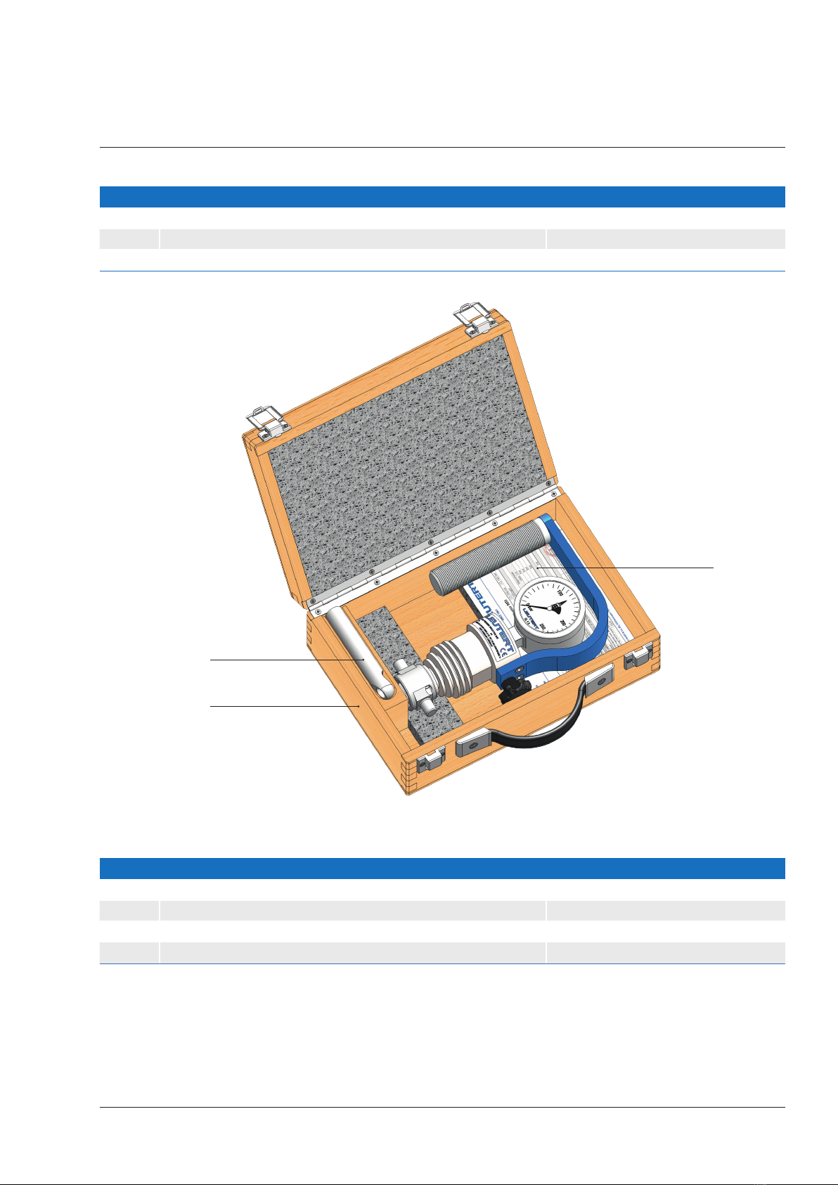
4 Maintenance
The MSI-3 was designed to be used without virtually any need for intensive maintenance. The
pressurized parts are manufactured from corrosion-resistant material and require no further care.
When using the MSI-3, take care that no particles of soot enter the instrument. After every period
of use, the tapered connection on the bottom part should be cleaned.
If the upper part is disconnected from the bottom part, the copper seals need to be replaced. The
same applies if the pressure gauge has been disconnected.
It must be ensured that even after prolonged periods of use correct measurement data can be
obtained. The instrument should therefore be returned to the LEUTERT factory or authorized
service center for testing and re-calibration every two years.
Please note, that the instrument itself must not get hotter than 60 °C.
WARNING
Do not exceed the maximum working temperature of 60°C. Detach the indicator
immediately from the indicator valve to prevent any unnecessary buildup of heat in the
instrument. After approximately 20 measurements allow the indicator to cool down for 10
to 15 minutes.
Close the indicator valve.
Note the readings.
Open the venting screw to reset the device to zero.
Now the next cylinder may be measured.
NOTICE
Store the indicator when not in use with the venting screw open in order to allow
condensation to escape, which may take a couple of hours.
© Friedrich Leutert GmbH & Co. KG, Adendorf, 2021
This document including all of its parts is protected by copyright. Any duplication or utilization
outside of the copyright law is not permitted without explicit permission from LEUTERT and may
be subject to prosecution. This applies in particular to duplications of any kind, translations and
incorporation into electronic systems.
– Original edition, manuals in other languages on request –
Table of contents
Other Leutert Measuring Instrument manuals