6
Operating Manual -MX-508 Stereo Microphone/Line Mixer
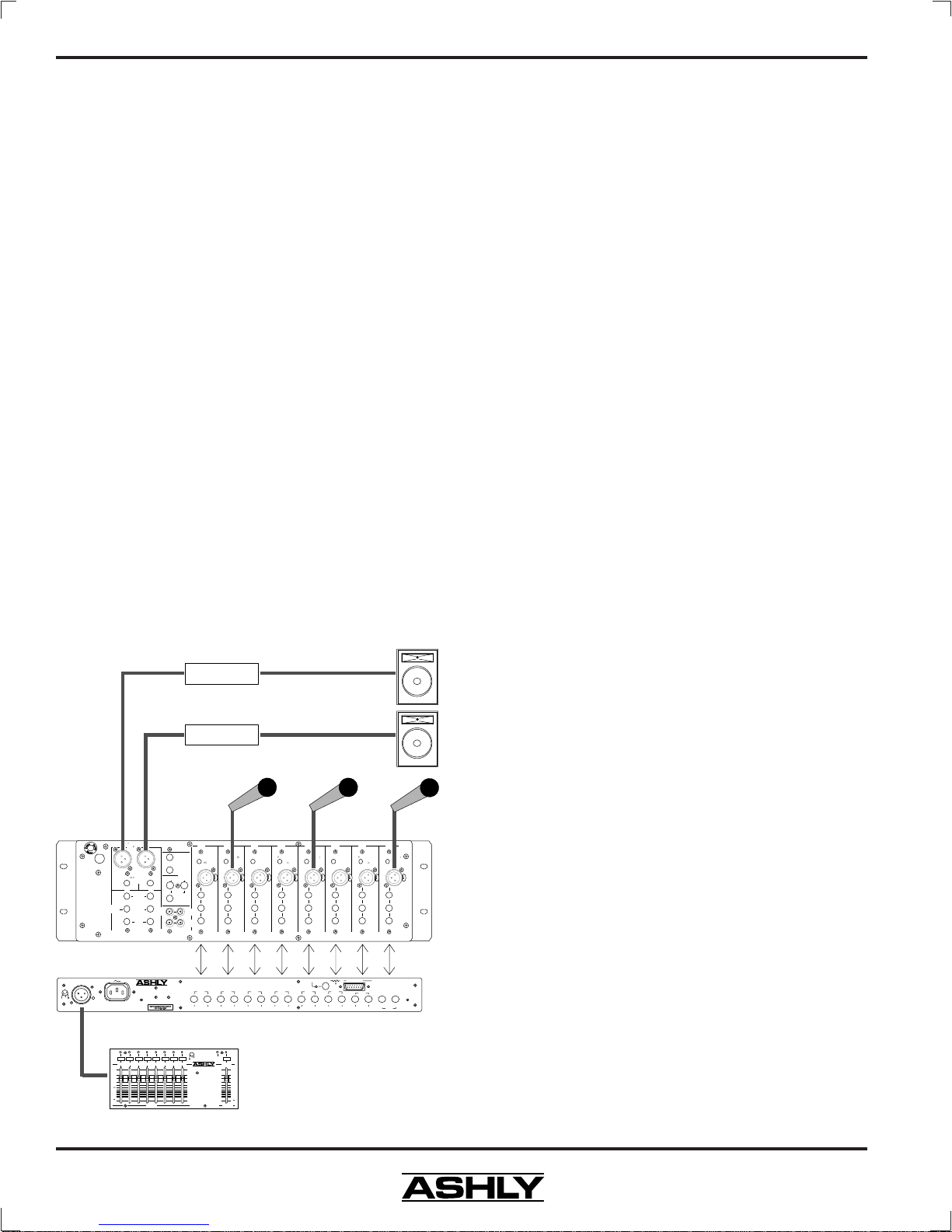
5. CONNECTIONS AND CABLES
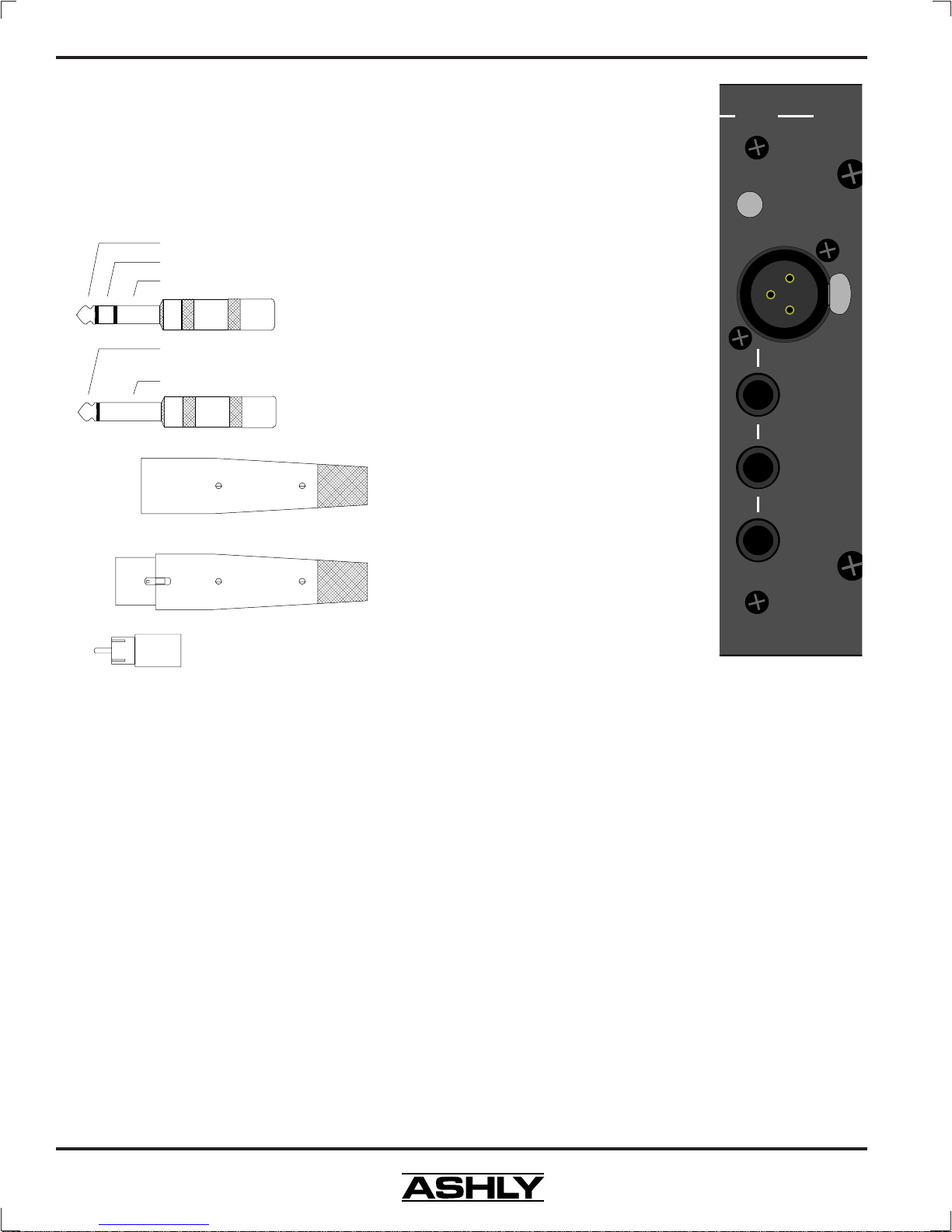
The MX-508 mixer is fitted with four types of
audio connectors: 3-pin XLR type male (stereo outputs),
3-pin XLR type female (mic inputs), tip-ring-sleeve (TRS)
phone jack, and RCA jack. Certain 1/4" jack connections
use an unbalanced mono plug, which is also shown.
Two-conductor (twisted pair) shielded cable is
best for all XLR type connections. Belden No. 8412, or
its equivalent, is an excellent cable due to its heavy con-
struction. This type of cable should be used for all por-
table applications. Snake cables containing multiple
shielded pairs must be handled very carefully because the
leads tend to be fragile, and a broken conductor is diffi-
cult to repair.
If low level and high level lines (e.g., microphones
and mixer line outputs), or if either of these lines and
speaker cables are run parallel for long distances, crosstalk
may be significant. In fact, the crosstalk (signal leakage
between cables) can cause an electronic feedback loop,
oscillation, and possibly damage to the equipment. To
minimize crosstalk, physically separate low level (micro-
phone) cables from speaker cables by the greatest feasible
distance. At any point where cables meet, run low level
cables perpendicular to high level or speaker cables. If
low and high level or speaker cables must be run parallel
and in close proximity to one another, they should be
bundled separately.
5.1 Microphone Input
The microphone input is an
active balanced type with a nominal
impedance of 1200 ohms. Its noise
performance is best with a 200 ohm
microphone. A plug-in transformer
option is available if you need the
isolation. The Mic input connector
is a standard 3-pin XLR female with
the shield on pin 1, the (+) in-phase
connection on pin 2, and the (-) out-
of-phase connection on pin 3.
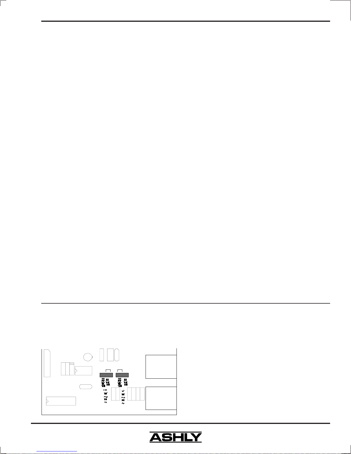
5.2 Input Pad
The Pad is a 20dB attenua-
tion switch on the rear panel for use
with the XLR microphone input. It
has no effect on the line input. It
should normally be left in the "out"
position for best signal to noise ra-
tio and should only be used when the
input is being overdriven with the
Gain control at its minimum setting.
5.3 Line Input
The line input is a standard
1/4" TRS active balanced connec-
tion, with a balanced input imped-
ance of 20KΩ. It will accommodate
a wide range of input levels.
5.4 Channel Send And Return Patch
A channel patch point allows a device such as graphic
equalizer, noise gate, compressor/limiter, remote level con-
troller, or direct out recording device to be used on individual
channels. The MX-508 has both single jack insert capabili-
ties as well as separate send and return jacks.
- To use separate send and return jacks, use the
send jack to feed the input of the device to be inserted, and
use the return jack for the output of the inserted device. You
must use unbalanced (tip-sleeve) mono plugs for this con-
figuration.
- To use the single jack insert, use a TRS (stereo)
plug in the send jack only, where the send output signal is on
the tip, and the return signal is applied to the ring. This
convention is most common among mixers.
- To use the send jack as a Direct Line Output
(pre EQ), you must use a special cable with tip and ring con-
nected at the MX-508 Send and a tip-sleeve mono plug at
the other end. Connecting tip and ring at the mixer send
jack is necessary for uninterrupted signal within the mixer
when using direct line outputs.
Ch.1
Pad (-20dB)
Mic
Input
Return
TRS
Insertion
( )
Send*
Line
Input
PUSH
PUSH
Stereo Phone Plug
used for balanced
Mono Phone Plug
used for unbalanced
Tip (+)
Ring (-)
Sleeve (Ground)
Tip (+)
Sleeve (Ground)
XLR
Male
2 = (+)
3 = (-)
1 = (gnd)
XLR pins are
numbered
in the
connector
insert.
XLR
Female
RCA Plug
Tip = (+)
Sleeve = ground