3
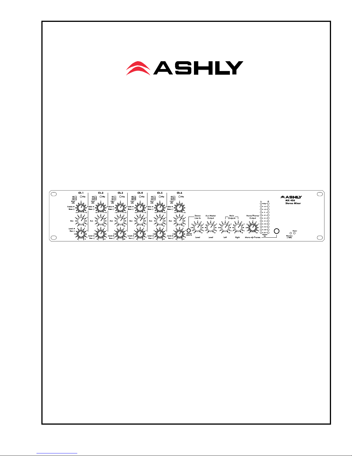
Operating Manual - MX-406 Stereo Microphone/Line Mixer
1. INTRODUCTION
Congratulations on your purchase of an Ashly
MX-406 stereo mic/line mixer, a professional, studio qual-
ity solution to everday mixing needs. MX-406 features
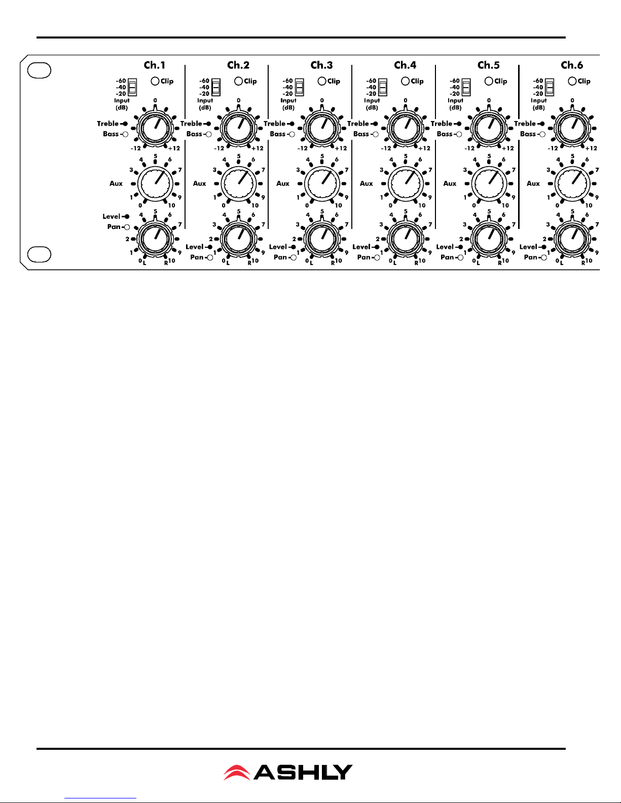
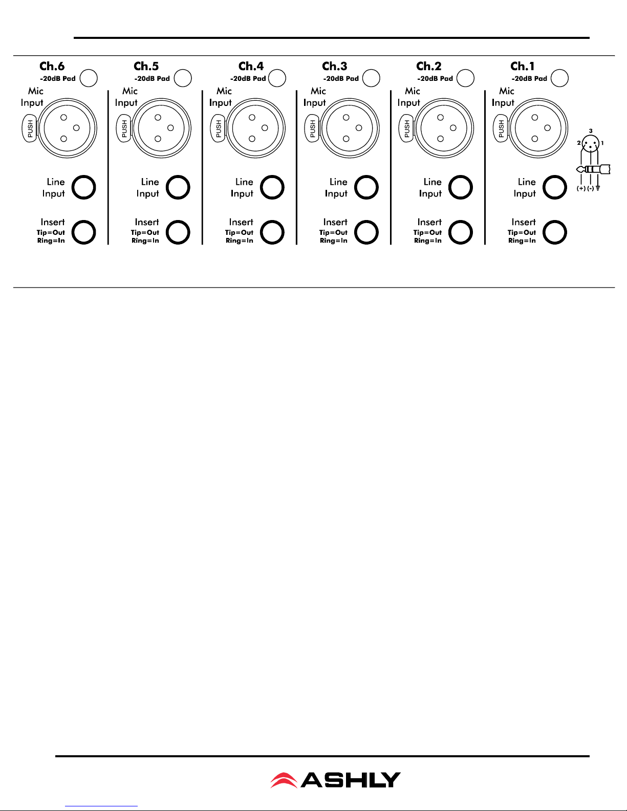
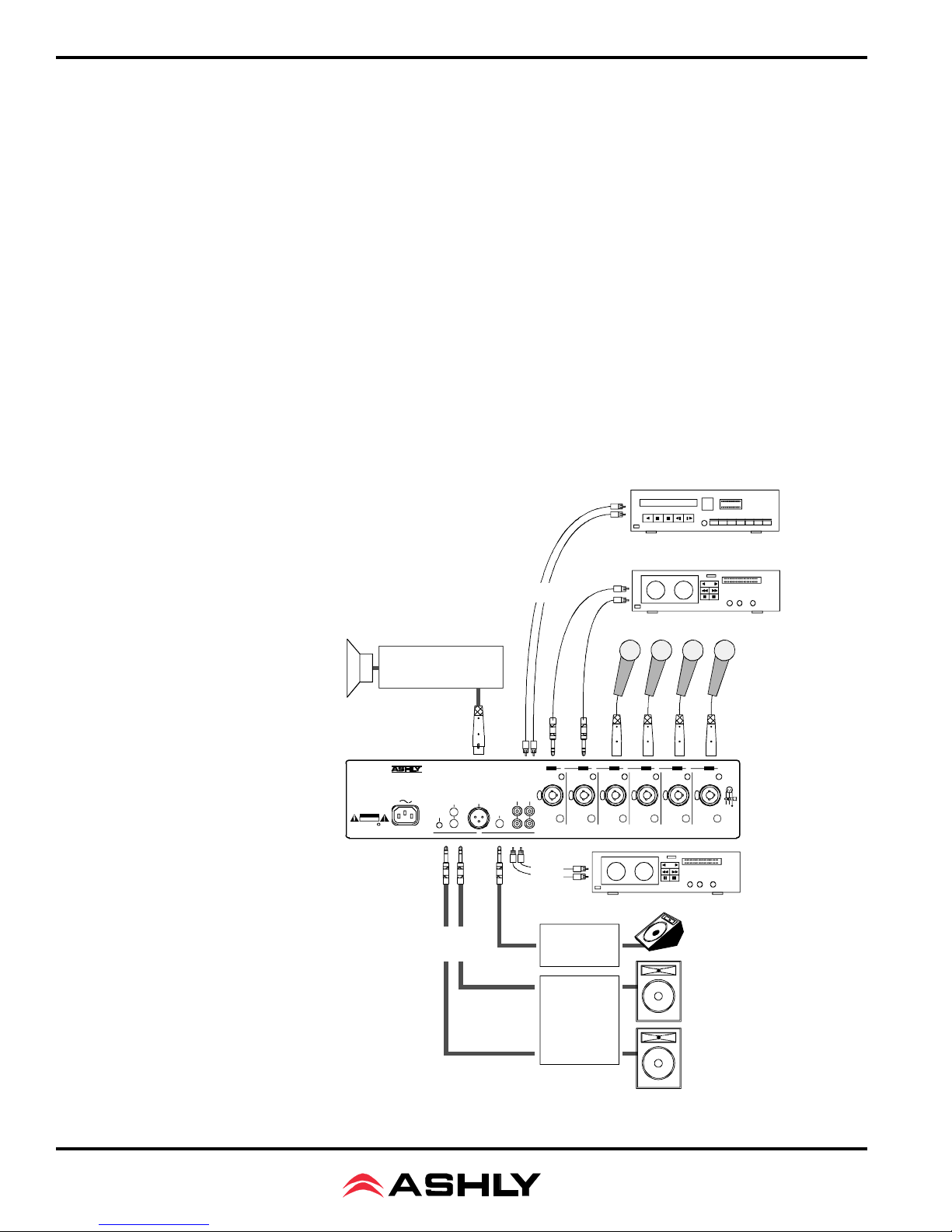
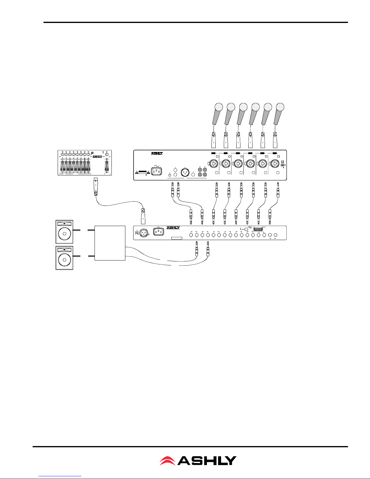
include six channels of mic or line inputs with mic input
pad, TRS insert points, and +48V phantom power. Each
channel has up to 60dB input gain, separate treble and
bass controls, an aux send control, level, and a stereo pan
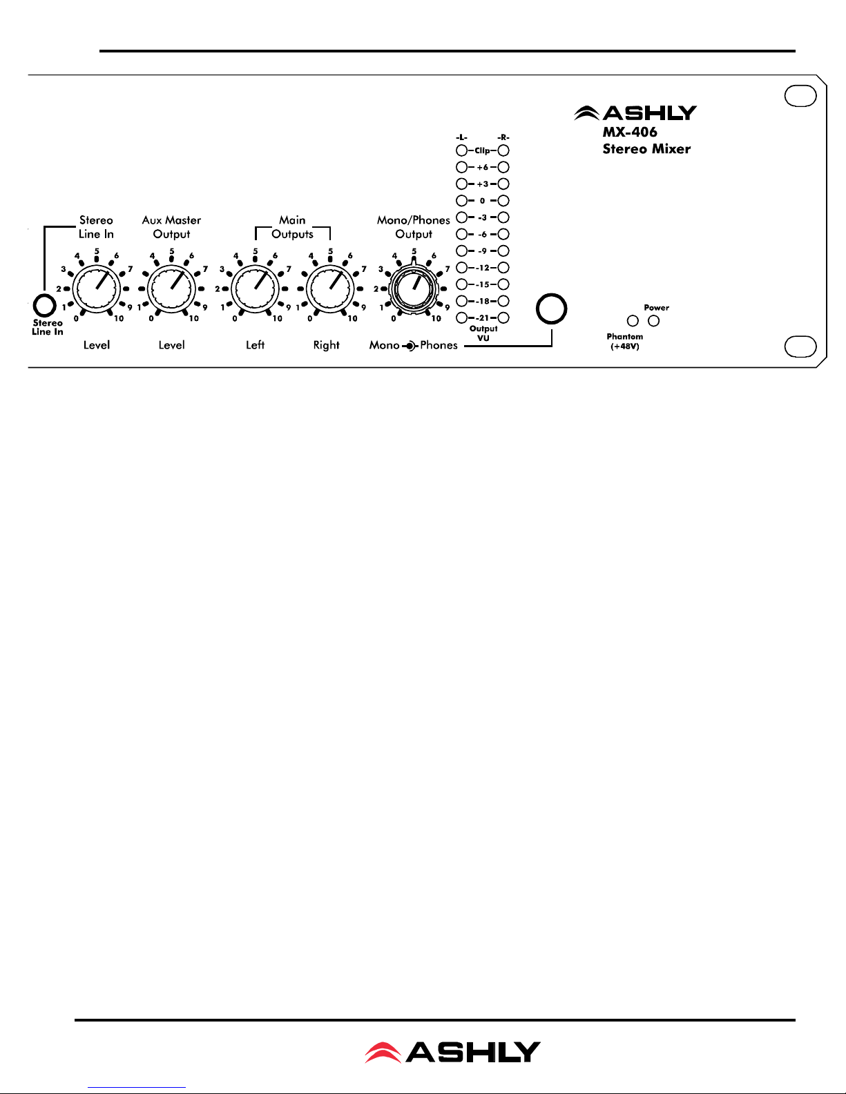
control. A stereo line input is provided for a stereo pro-
gram source such as tape, CD, or MP3 player. Outputs
include aux master, stereo line out (pre-master), stereo left
and right, transformer balanced mono out, and stereo head-
phones. A full 11 segment LED array indicates stereo
output level.
Stereo main outputs use 1/4" jacks, stereo line
input and line out use RCA connectors, and there is an
additional 3.5mm jack on the front panel for stereo line in.
A transformer isolated 600 ohm mono output uses an XLR
connector. Ashly mixers still use professional quality
16mm metal shaft potentiometers for greater accuracy and
long life and of course, Ashly products come with a worry-
free five year warranty.
2. UNPACKING
As a part of our system of quality control, every
Ashly product is carefully inspected before leaving the
factory to ensure flawless appearance. After unpacking,
please inspect for any physical damage. Save the ship-
ping carton and all packing materials , as they were care-
fully designed to reduce to minimum the possibility of
transportation damage should the unit again require pack-
ing and shipping. In the event that damage has occurred,
immediately notify your dealer so that a written claim to
cover the damages can be initiated.
The right to any claim against a public carrier
can be forfeited if the carrier is not notified promptly and
if the shipping carton and packing materials are not avail-
able for inspection by the carrier. Save all packing mate-
rials until the claim has been settled.
3. AC POWER REQUIREMENTS
The MX-406 mixer will perform normally from
100 to 240 volts AC, 50-60Hz. Use only properly
grounded AC receptacles. To reduce the risk of ground
loop hum, use a central point for system AC power distri-
bution. Power consumption is less than 30 watts.
WARNING:
THIS APPARATUS MUST BE EARTHED
The exclamation point within an eqilateral
triangle is intended to alert the user to the
presence of important operating and
maintenance instructions in the literature
accompanying the device.
The lightning flash with arrowhead
symbol, within an equilateral triangle, is
intended to alert the user to the presence
of uninsulated "dangerous voltage"
within the product's enclosure that may be
of sufficient magnitude to constitute a risk
of electric shock to persons. TO REDUCE THE RISK OF ELECTRIC SHOCK, DO NOT RE-
MOVE COVER. NO USER SERVICEABLE PARTS INSIDE.
REFER SERVICING TO QUALIFIED SERVICE PERSONNEL.
TO REDUCE THE RISK OF FIRE OR ELECTRICAL SHOCK,
DO NOT EXPOSE THIS APPlIANCE TO RAIN OR MOISTURE.
CAUTION
RISK OF ELECTRIC SHOCK
DO NOT OPEN