manuals.online logo
Brands
  1. Home
  2. •
  3. Brands
  4. •
  5. ASROCK
  6. •
  7. Motherboard
  8. •
  9. ASROCK IMB-1712 Service manual

ASROCK IMB-1712 Service manual

14 : 5-pin Thunderbolt AIC Connector (TB1)
15 :
USB 3.2 Gen1 Header
(
USB3_5_6)
16 : DACC1
Short : ACC
Open : no ACC
17 : ATX/AT Mode Jumper (SIO_AT1)
Open : ATX Mode
Short : AT Mode
COM Port Pin9 PWR Setting Jumpers
18 : PWR_COM3 (For COM Port3)
PWR_COM4 (For COM Port4)
PWR_COM5 (For COM Port5)
PWR_COM6 (For COM Port6)
34 : PWR_COM1 (For COM Port1)
PWR_COM2 (For COM Port2)
1-2 : +5V
2-3 : +12V
19 :
COM Port Headers (COM3~6) (RS232)
20 : Clear CMOS Header (CLRMOS2)
Open : Normal
Short : Auto Clear CMOS (Power O󰀨)
8 : SATA3 Connectors (SATA3_0 ~ SATA3_3)
10 :
Clear CMOS Header (CLRMOS1)
1-2 : Normal
2-3 : Clear CMOS
11 :
M.2 Key-B Socket (M2_B1)
12 :
M.2 Key-E Socket (M2_E1)
13 : 3-pin Thunderbolt AIC Connector (TB2)
Chassis FAN Connectors (+12V)
1 : CHA_FAN1
9 : CHA_FAN2
3 : CHA_FAN3
2 : ATX 12V Power Connector
4 :
CPU FAN Connector (+12V)
5 : PWR LOSS Jumper (PWR_LOSS1)
Short : Power Loss
Open : no Power Loss
6
:
24-pin ATX Power Input Connector
7 :
M.2 Key-M Socket (M2_M1)
IMB-1712
Jumpers and Headers Setting Guide
The terms HDMI® and HDMI High-Denition
Multimedia Interface, and the HDMI logo are
trademarks or registered trademarks of HDMI
Licensing LLC in the United States and other
countries.
12
1
24
13
GND
+12V
CPU_FAN_SPEED
FAN_SPEED_CONTROL
GND
+12V
CHA_FAN_SPEED
FAN_SPEED_CONTROL
4 1
8 5 1
IntA_P1_D+
ID
IntA_P1_D-
GND
IntA_P1_SSTX+
GND
IntA_P1_SSTX-
IntA_P1_SSRX+
IntA_P1_SSRX-
VbusVbus
Vbus
IntA_P0_SSRX-
IntA_P0_SSRX+
GND
IntA_P0_SSTX-
IntA_P0_SSTX+
GND
IntA_P0_D-
IntA_P0_D+
GND
+12V
CHA_FAN_SPEED
FAN_SPEED_CONTROL
* Auto clear CMOS when system boot improperly.
Revision History
Date Description
March 7, 2022 First Release
PIN Signal
Name PIN Signal
Name PIN Signal
Name
1
TBT_
RTD3_
RESET#
2
TBT_
RTD3_
PWR_EN
3
TBT_
RTD3_
WAKE#
1PIN Signal
Name PIN Signal
Name PIN Signal
Name PIN Signal
Name PIN Signal
Name
5 GND 4
TBT_
SLP_S5_
S4#
3SLP_
S3# 2
TBCIO_
PLUG_
EVENT_
R2
1
TB_
FRC_
PWR
21 : Chassis Intrusion Headers (CI1, CI2)
CI1 :
Close
: Active Case Open
Open : Normal
CI2 :
Close
: Normal
Open : Active Case Open
22 : Printer Port / GPIO Header (LPT_GPIO1)
Printer Port: GPIO:
23 : ESPI Header
24
: Digital Input / Output Power Select
(JGPIOPWR) (JGPIO_PWR1)
1-2 : +12V
2-3 : +5V
3-4 : +5V
4-5 : GND
25 :
Digital Input / Output
Default Value
Setting (JGPIO_SET1)
1-2 : Pull-High
2-3 : Pull-Low
26 :
USB 2.0 Headers
(
USB2_10_11,
USB2_12_13)
27 :
System Panel Header
28 : SMBUS_TEST1
29 : SPDIF Header
30 :
Front Panel Audio Header
31 : Buzzer (BUZZ2)
32 :
PS/2 Keyboard/Mouse Header
33 : LAN LED Headers :
I225_LED1 (For LAN1 Port)
I225_LED2 (For LAN2 Port)
I219_LED1 (For LAN3 Port)
+5V
1
SP D0
STB#
SP D1
SP D2
SP D3
SP D4
SP D6
SP D7
GN D
GN D
SLIN#
PINIT#
ERROR#
AFD#
GN D
GN D
GN D
GN D
GN D
GN D
SP D5
ACK#
BUSY
PE
SLCT
*
If you want to use the printer port function, please
short pin4 and pin5 on
Digital Input / Output Power Select (JGPIO_PWR1).
PIN Signal Name PIN Signal Name
26 NC 25 NA
24 GND 23 SIO_GP70
22 GND 21 SIO_GP71
20 GND 19 SIO_GP72
18 GND 17 SIO_GP87
16 GND 15 SIO_GP86
14 GND 13 SIO_GP85
12 JGPIOPWR 11 SIO_GP84
10 JGPIOPWR 9 SIO_GP83
8 SIO_GP73 7 SIO_GP82
6 SIO_GP74 5 SIO_GP81
4 SIO_GP75 3 SIO_GP80
2 SIO_GP76 1 SIO_GP77
1
PIN Signal
Name PIN Signal
Name PIN Signal Name PIN Signal
Name
1 +3V 2 SMB_CLK 3 SMB_DATA 4 GND
35 :
Audio Jacks
Blue - Line In
Green - Line Out
Pink - Mic In
36 :
Top : RJ45 LAN Port (LAN1)
Bottom : USB 3.2 Gen2 Ports (USB3_3_4)
37 :
Top : RJ45 LAN Port (LAN2)
Middle : USB 3.2 Gen2 Port (USB3_9)
Bottom : USB 3.2 Gen2 Type-C Port
(USB32_TC_1)
38 :
Top : COM Port (COM2) (RS232/422/485)*
Bottom :
D-Sub Port (VGA1)
39 :
Top : COM Port (COM1) (RS232/422/485)*
Bottom Right : DisplayPort (DP1)
Bottom Left:
HDMI Port (HDMI1)
40 :
USB 3.2 Gen2 Ports (USB3_1_2)
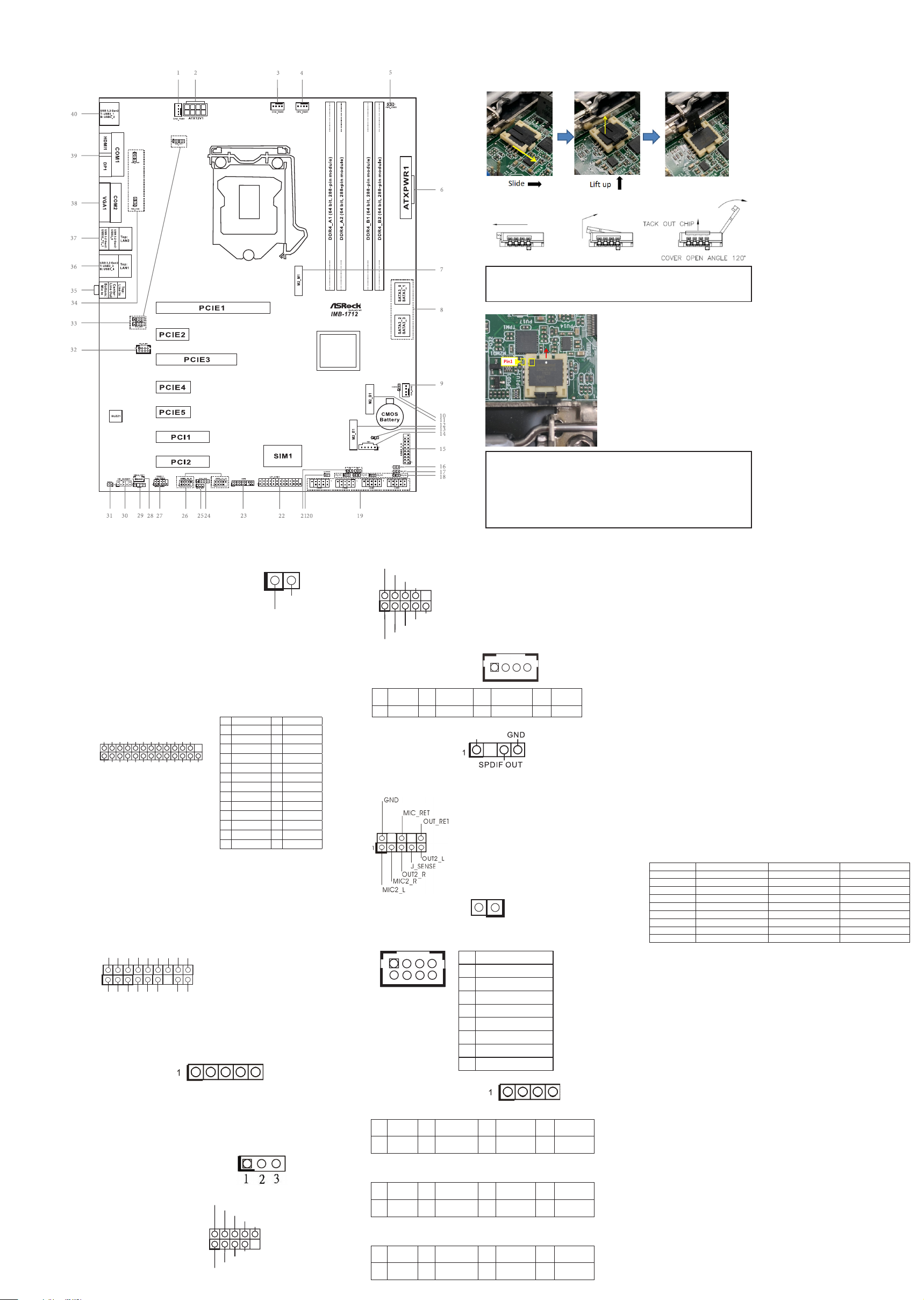
Installation of ROM Socket
* Do not apply force to the actuator cover after ic inserted.
* Do not apply force to actuator cover when it is opening over 120
degree, Otherwise, the actuator cover may be broken.
* The yellow dot (Pin1) on the ROM must be installed at pin1 position of
the socket (white arrow area).
* Make sure the white dot on the ROM is installed outwards of the
socket.
* For further details of how to install ROM, please refer to ASRI website.
Warning: If the installation does not follow as the picture, then it
may cause severe damage to chipset & MB.
DUMMY
GND
GND
P+
P-
USB_PWR
P+
P-
USB_PWR
1
1
1
PIN Signal Name
1 KBCLK
2 +5V
3 KBDATA
4 +5V
5 MSDATA
6 GND
7 MSCLK
8 GND
* This motherboard supports RS232/422/485 on COM1, 2 ports. Please
refer to below table for the pin denition. In addition, COM1, 2 ports
(RS232/422/485) can be adjusted in BIOS setup utility > Advanced
Screen > Super IO Conguration. You may refer to our user manual
for details.
COM1, 2 Port Pin Denition
PIN RS232 RS422 RS485
1 DCD, Data Carrier Detect TX- RTX-
2 RXD, Receive Data RX+ N/A
3 TXD, Transmit Data TX+ RTX+
4 DTR, Data Terminal Ready RX- N/A
5 GND GND GND
6 DSR, Data Set Ready N/A N/A
7 RTS, Request To Send N/A N/A
8 CTS, Clear To Send N/A N/A
9 No Power/5V/12V N/A N/A
1
GND
SMB_DATA_MAIN
LAD2
LAD1
GND
S_PWRDWN#
SERIRQ#
GND
PCICLK
PCIRST#
LAD3
+3V
LAD0
+3VSB
GND
FRAME SMB_CLK_MAIN
PIN Signal
Name PIN Signal Name PIN Signal
Name PIN Signal
Name
1 LILEDP 2 LED_LNK#_
ACT 3 LED_1000# 4 LED_2500#
PIN Signal
Name PIN Signal Name PIN Signal
Name PIN Signal
Name
1 LILEDP 2 LED_LNK#_
ACT 3 LED_1000# 4 LED_2500#
PIN Signal
Name PIN Signal Name PIN Signal
Name PIN Signal
Name
1 LILEDP 2 LED_LNK#_
ACT 3 LED_100# 4 LED_1000#
1
Signal
GND
GND
RESET#
PWRBTN#
PLED-
PLED+
GND
HDLED-
HDLED+
1
GND
HLED+

Other ASROCK Motherboard manuals

ASROCK Z87 OC Formula ac User manual

ASROCK

ASROCK Z87 OC Formula ac User manual

ASROCK ALIVENF5SLI-1394 User manual

ASROCK

ASROCK ALIVENF5SLI-1394 User manual

ASROCK Z390  Phantom Gaming 9 User manual

ASROCK

ASROCK Z390 Phantom Gaming 9 User manual

ASROCK 939NF4G-SATA2 User manual

ASROCK

ASROCK 939NF4G-SATA2 User manual

ASROCK H610M-ITX/eDP User manual

ASROCK

ASROCK H610M-ITX/eDP User manual

ASROCK iBOX-V2000 Series User manual

ASROCK

ASROCK iBOX-V2000 Series User manual

ASROCK H370M-HDV/M.2 User manual

ASROCK

ASROCK H370M-HDV/M.2 User manual

ASROCK 890GX EXTREME4 User manual

ASROCK

ASROCK 890GX EXTREME4 User manual

ASROCK P55 EXTREME User manual

ASROCK

ASROCK P55 EXTREME User manual

ASROCK AOD790GX-128M User manual

ASROCK

ASROCK AOD790GX-128M User manual

ASROCK PHANTOM GAMING A620I LIGHTNING WiFi User manual

ASROCK

ASROCK PHANTOM GAMING A620I LIGHTNING WiFi User manual

ASROCK N68-GS UCC - User manual

ASROCK

ASROCK N68-GS UCC - User manual

ASROCK B760M PC LIGHTNING User manual

ASROCK

ASROCK B760M PC LIGHTNING User manual

ASROCK G41M-PS User manual

ASROCK

ASROCK G41M-PS User manual

ASROCK X299 Steel Legend User manual

ASROCK

ASROCK X299 Steel Legend User manual

ASROCK B550M Steel Legend User manual

ASROCK

ASROCK B550M Steel Legend User manual

ASROCK IMB-1713 User manual

ASROCK

ASROCK IMB-1713 User manual

ASROCK H61DEL User manual

ASROCK

ASROCK H61DEL User manual

ASROCK K10N78M PRO User manual

ASROCK

ASROCK K10N78M PRO User manual

ASROCK K10N78FullHD-hSLI R3.0 User manual

ASROCK

ASROCK K10N78FullHD-hSLI R3.0 User manual

ASROCK H81TM-ITX User manual

ASROCK

ASROCK H81TM-ITX User manual

ASROCK Z170 OC FORMULA User manual

ASROCK

ASROCK Z170 OC FORMULA User manual

ASROCK H67M User manual

ASROCK

ASROCK H67M User manual

ASROCK H67DE User manual

ASROCK

ASROCK H67DE User manual

Popular Motherboard manuals by other brands

Huananzhi X79-6MV2.0 user manual

Huananzhi

Huananzhi X79-6MV2.0 user manual

Texas Instruments TPS2663-166EVM user guide

Texas Instruments

Texas Instruments TPS2663-166EVM user guide

Nuvoton NuMaker NUC1262SE user manual

Nuvoton

Nuvoton NuMaker NUC1262SE user manual

Xilinx SP605 Hardware user's guide

Xilinx

Xilinx SP605 Hardware user's guide

Asus B85M-E user manual

Asus

Asus B85M-E user manual

Asus P5MT-C user manual

Asus

Asus P5MT-C user manual

Asus P4P800-VM user guide

Asus

Asus P4P800-VM user guide

Texas Instruments WL1837MODCOM8I user guide

Texas Instruments

Texas Instruments WL1837MODCOM8I user guide

Linear DC2106A-B Demo Manual

Linear

Linear DC2106A-B Demo Manual

Atmel ATMEGA256RFR2-ZUR user guide

Atmel

Atmel ATMEGA256RFR2-ZUR user guide

Texas Instruments AMC1210MB-EVM user guide

Texas Instruments

Texas Instruments AMC1210MB-EVM user guide

Texas Instruments ADS8861EVM-PDK user guide

Texas Instruments

Texas Instruments ADS8861EVM-PDK user guide

Supero X8STE user manual

Supero

Supero X8STE user manual

Gigabyte GA-6VXE7+ user manual

Gigabyte

Gigabyte GA-6VXE7+ user manual

EMAC PCM-6892E user manual

EMAC

EMAC PCM-6892E user manual

Nexcom EBC 500 Series user manual

Nexcom

Nexcom EBC 500 Series user manual

Asus P4C800 Deluxe user guide

Asus

Asus P4C800 Deluxe user guide

ST SPC572LADPT100S user manual

ST

ST SPC572LADPT100S user manual

manuals.online logo
manuals.online logoBrands
  • About & Mission
  • Contact us
  • Privacy Policy
  • Terms and Conditions

Copyright 2025 Manuals.Online. All Rights Reserved.