manuals.online logo
Brands
  1. Home
  2. •
  3. Brands
  4. •
  5. ASROCK
  6. •
  7. Motherboard
  8. •
  9. ASROCK IMB-390-L Service manual

ASROCK IMB-390-L Service manual

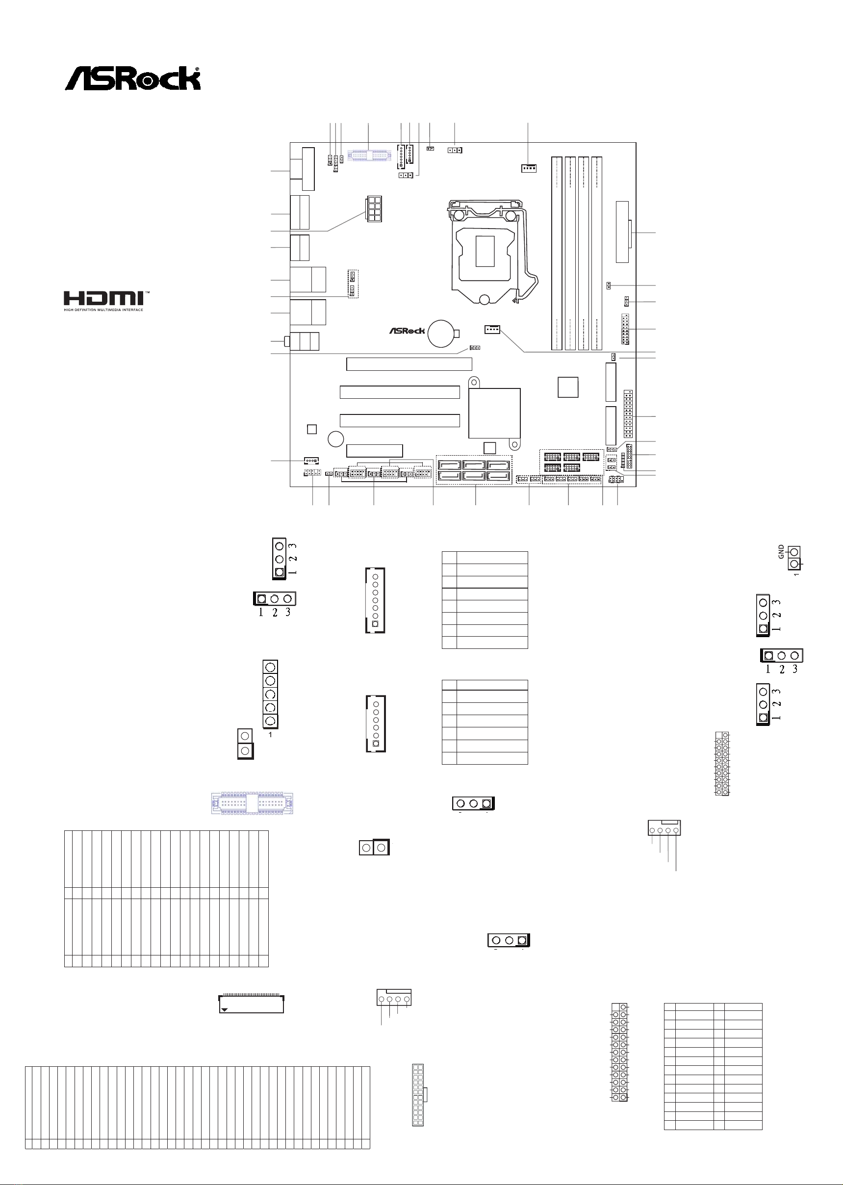
12 : PWR LOSS Header (PWR_LOSS1)
Short : Power Loss
Close : no Power Loss
USB Power Setting Jumpers
13 : USB3_PWR3 (For USB3_5_6)
28 : USB2_PWR1 (For USB2_4_5)
USB2_PWR2 (For USB2_6_7)
USB2_PWR3 (For USB2_9_10)
35 : USB3_PWR1 (For USB3_1_2)
USB3_PWR2 (For USB3_3_4)
14 : USB 3.0 Header
(
USB3_5_6
)
15 :
Chassis FAN Connector (+12V)
16 : MSATA Select (MSATA_SEL1)
(mini-SATA is shared with SATA3_6)
Short : Use mini-SATA
Open : Use SATA3_6
17 : Printer Port / GPIO Header (LPT_GPIO1)
Printer Port: GPIO:
5 : Backlight & Amp Volume Control
(BLT_VOL1)
6 : Inverter Power Control Wafer
(BLT_PWR1)
7 : Backlight Control Level (BLT_PWM1)
(CON_LBKLT_CTL)
1-2 : +3V (eDP)
2-3 : +5V (LVDS)
8 : BL1
Open: Protect LCD_BLT_VCC
Short: No Protect LCD_BLT_VCC
9 : Backlight Power Select
(LCD_BLT_VCC) (BKT_PWR1)
1-2 : LCD_BLT_VCC : +5V
2-3 : LCD_BLT_VCC : +12V
10 :
CPU FAN Connector (+12V)
11 :
24-pin ATX Power Input Connector
COM Port Pin9 PWR Setting Jumpers
1 : PWR_COM1 (For COM Port1)
24 : PWR_COM2 (For COM Port2)
PWR_COM3 (For COM Port3)
PWR_COM4 (For COM Port4)
PWR_COM5 (For COM Port5)
PWR_COM6 (For COM Port6)
2 : Panel Power Select (PNL_PWR1)
1-2 : +3V
2-3 : +5V
4-5 : +12V
3 : BL2
Open: Protect LCD_VCC
Short: No Protect LCD_VCC
4* : LVDS Panel Connector
(Only for IMB-390-L)
* eDP Connector
(on the Backside of PCB)
(
Only for IMB-390-D
)
IMB-390-L
IMB-390-D
Jumpers and Headers Setting Guide
ATXPWR1
PCI1
PCI2
PCIE1
PCIE2
1
HD_AUDIO1
CMOS
Battery
HDLED RESET
PLED PWRBTN
PANEL1
1
Super
I/O
SATA3_3
SATA3_1
SATA3_2 SATA3_4
CLRMOS2
1
CPU_FAN1
USB2_4_5
1
CI2
1
CI1
Top:
RJ-45
USB 3.0
T: USB3
B: USB4
1
LVDS 1
BLT_PWR1
1
BLT_VOL1
1
BUZZ1
Top:
Line In
Center:
Line Out
Bottom:
Mic In
SPEAKER1
1
VGA1*
IMB-390
PNL_PWR1
1
BKT_PWR1
1
ATX12 V1
AUDIO
CODEC
1
BLT_PWM1
LPC1
1
DDR4_A2 (64 bit, 288-pin module)
DDR4_A1 (64 bit, 288-pin module)
DDR4_B2 (64 bit, 288-pin module)
DDR4_B1 (64 bit, 288-pin module)
Industrial
BIOS
ROM
1
BL2
1
PWR_COM1
1
BL1
1
PWR_LOSS1
1
USB3_PWR3
USB3_5_6
1
PWR_JP1
1
CHA_FAN1
mini-SATA
mini-PCIe
1
LPT_GPIO1
1
USB3_PWR1
1
USB3_PWR2
1
BUZZ2
1
USB2_PWR1
1
USB2_PWR2
USB2_6_7
1
USB2_9_10
1
1
USB2_PWR3
SATA3_5
SATA3_6
CLRMOS1
1
PWR_COM3
1
PWR_COM4
1
PWR_COM5
1
PWR_COM6
1
JGPIO_SET1
1
1
JGPIO_PWR1
1
PWR_COM2
1
COM1
PS2
Keyboard
/Mouse
DVI1
Top:
RJ-45
USB 3.0
T: USB1
B: USB2
HDMI1
DP1
12 3 4* 578910
11
6
20
19
18
17
15
14
13
12
25 24 23 22
21
34
32
31
30 29 28 27 26
33
39*
38
37
36
35
40
1
MSATA _SE L1
COM 2
1
COM 4
1
COM 3
1
COM 5
1
COM6
1
16
GND
+12V
CPU_FAN_SPEED
FAN_SPEED_CONTROL
12
1
24
13
1
IntA_PB_D+
Dummy
IntA_PB_D-
GND
IntA_PB_SSTX+
GND
IntA_PB_SSTX-
IntA_PB_SSRX+
IntA_PB_SSRX-
VbusVbus
Vbus
IntA_PA_SSRX-
IntA_PA_SSRX+
GND
IntA_PA_SSTX-
IntA_PA_SSTX+
GND
IntA_PA_D-
IntA_PA_D+
1
SPD0
STB#
SPD1
SPD2
SPD3
SPD4
SPD6
SPD7
GND
GND
SLIN#
PINIT#
ERROR#
AFD#
GND
GND
GND
GND
GND
GND
SPD5
ACK#
BUSY
PE
SLCT
*
If you want to use the printer port function, please
short pin4 and pin5 on
Digital Input / Output Power Select (JGPIO_PWR1).
PIN Signal Name PIN Signal Name
26 NC 25 NA
24 GND 23 SIO_GP30
22 GND 21 SIO_GP31
20 GND 19 SIO_GP32
18 GND 17 SIO_GP33
16 GND 15 SIO_GP34
14 GND 13 SIO_GP35
12 JGPIOPWR 11 SIO_GP36
10 JGPIOPWR 9 SIO_GP37
8 SIO_GP43 7 SIO_GP40
6 SIO_GP44 5 SIO_GP41
4 SIO_GP45 3 SIO_GP42
2 SIO_GP46 1 SIO_GP47
The terms HDMI™ and HDMI High-Denition
Multimedia Interface, and the HDMI logo are
trademarks or registered trademarks of HDMI
Licensing LLC in the United States and other
countries.
1
40
2
139
PIN Signal Name PIN Signal Name
2 R_LVDD 1 R_LVDD
4 LDDC_CLK 3 +3V
6 LVDS_A_DATA0# 5 LDDC_DATA
8 GND 7 LVDS_A_DATA0
10 LVDS_A_DATA1 9 LVDS_A_DATA1#
12 LVDS_A_DATA2# 11 GND
14 GND 13 LVDS_A_DATA2
16 LVDS_A_DATA3 15 LVDS_A_DATA3#
18 LVDS_A_CLK# 17 GND
20 GND 19 LVDS_A_CLK
22 LVDS_B_DATA0 21 LVDS_B_DATA0#
24 LVDS_B_DATA1# 23 GND
26 GND 25 LVDS_B_DATA1
28 LVDS_B_DATA2 27 LVDS_B_DATA2#
30 LVDS_B_DATA3# 29 DPLVDD_EN
32 GND 31 LVDS_B_DATA3
34 LVDS_B_CLK 33 LVDS_B_CLK#
36 CON_LBKLT_EN_R 35 GND
38 LCD_BLT_VCC 37 CON_LBKLT_CTL_R
40 LCD_BLT_VCC 39 LCD_BLT_VCC
PIN Signal Name
40 NA
39 LCD_BLT_VCC
38 LCD_BLT_VCC
37 LCD_BLT_VCC
36 LCD_BLT_VCC
35 SMB_CLK
34 SMB_DATA
33 CON_LBKLT_CTL
32 CON_LBKLT_EN
31 GND
30 GND
29 GND
28 GND
27 eDP_HPD_CON
26 GND
25 GND
24 GND
23 GND
22 NA
21 LCD_VCC
20 LCD_VCC
19 LCD_VCC
18 LCD_VCC
17 GND
16 eDP_AUX#_CON
15 eDP_AUX_CON
14 GND
13 eDP_TX0_CON
12 eDP_TX#0_CON
11 GND
10 eDP_TX1_CON
9 eDP_TX#1_CON
8 GND
7 eDP_TX2_CON
6 eDP_TX#2_CON
5 GND
4 eDP_TX3_CON
3 eDP_TX#3_CON
2 GND
1 NA
PIN Signal Name
7 GND
6 GND
5 GPIO_BLT_DW
4 GPIO_BLT_UP
3 PWRDN
2 GPIO_VOL_DW
1 GPIO_VOL_UP
1
PIN Signal Name
1 GND
2 GND
3 CON_LBKLT_CTL
4 CON_LBKLT_EN
5 LCD_BLT_VCC
6 LCD_BLT_VCC
1
1
3 2 1
+5VSB_ATX
GND
+12V
CHA_FAN_SPEED
FAN_SPEED_CONTROL
3 2 1
40
1
EDP1
P/ N: 15G06M046000AK V1.0
*15G06M046000AK*
18 :
Digital Input / Output Power Select
(JGPIO_SET1)
1-2 : +5V
2-3 : GND
19 : LPC Header
20 : Digital Input / Output Power Select
(JGPIOPWR) (JGPIO_PWR1)
1-2 : +12V
2-3 : +5V
3-4 : +5V
4-5: GND
21 : Chassis Intrusion Headers
(CI1, CI2)
Short
: Active Case Open
Open : Normal
22 :
System Panel Header
23 : COM Port Headers (COM2, 3, 4, 5, 6)
(RS232)
25 : Clear CMOS Headers
CLRMOS1 :
1-2 : Normal
2-3 : Clear CMOS
CLRMOS2 :
1-2 : +BATT
2-3 : +3VSB_A
26 : SATA3 Connectors (SATA3_1 ~ SATA3_6)
(SATA3_6 is share with mini-SATA)
27 :
USB 2.0 Headers (
USB2_4_5, USB2_6_7,
USB2_9_10
)
29 : Buzzer (BUZZ2)
30 :
Front Panel Audio Header
31 : 3W Audio AMP Output Wafer
32 : ATX/AT Mode Jumper (PWR_JP1)
1-2 : AT Mode
2-3 : ATX Mode
33 :
Audio Jacks
Blue - Line In
Green - Line Out
Pink - Mic In
34 :
Top : RJ45 LAN Port (LAN2)
Bottom : USB 3.0 Ports (USB3_3_4)
36 :
Top : RJ45 LAN Port (LAN1)
Bottom : USB 3.0 Ports (USB3_1_2)
37 :
Top : DisplayPort (DP1)
Bottom : HDMI Port (HDMI1)
38 : ATX 12V Power Connector
39 :
Top : D-Sub Port (VGA1)*
(
Only for IMB-390-L
)
Bottom : DVI Port (DVI1)
ATXPWR1
PCI1
PCI2
PCIE1
PCIE2
1
HD_AUDIO1
CMOS
Battery
HDLED RESET
PLED PWRBTN
PANEL1
1
Super
I/O
SATA3_3
SATA3_1
SATA3_2 SATA3_4
CLRMOS2
1
CPU_FAN1
USB2_4_5
1
CI2
1
CI1
Top:
RJ-45
USB 3.0
T: USB3
B: USB4
1
LVDS 1
BLT_PWR1
1
BLT_VOL1
1
BUZZ1
Top:
Line In
Center:
Line Out
Bottom:
Mic In
SPEAKER1
1
VGA1*
IMB-390
PNL_PWR1
1
BKT_PWR1
1
ATX12V 1
AUDIO
CODEC
1
BLT_PWM1
LPC1
1
DDR4_A2 (64 bit, 288-pin module)
DDR4_A1 (64 bit, 288-pin module)
DDR4_B2 (64 bit, 288-pin module)
DDR4_B1 (64 bit, 288-pin module)
Industrial
BIOS
ROM
1
BL2
1
PWR_COM1
1
BL1
1
PWR_LOSS1
1
USB3_PWR3
USB3_5_6
1
PWR_JP1
1
CHA_FAN1
mini-SATA
mini-PCIe
1
LPT_GPIO1
1
USB3_PWR1
1
USB3_PWR2
1
BUZZ2
1
USB2_PWR1
1
USB2_PWR2
USB2_6_7
1
USB2_9_10
1
1
USB2_PWR3
SATA3_5
SATA3_6
CLRMOS1
1
PWR_COM3
1
PWR_COM4
1
PWR_COM5
1
PWR_COM6
1
JGPIO_SET1
1
1
JGPIO_PWR1
1
PWR_COM2
1
COM1
PS2
Keyboard
/Mouse
DVI1
Top:
RJ-45
USB 3.0
T: USB1
B: USB2
HDMI1
DP1
12 3 4* 578910
11
6
20
19
18
17
15
14
13
12
25 24 23 22
21
34
32
31
30 29 28 27 26
33
39*
38
37
36
35
40
1
MSATA _S EL1
COM 2
1
COM 4
1
COM 3
1
COM 5
1
COM6
1
16
40 :
Top : COM Port (COM1)
(RS232/422/485)*
Bottom : PS/2 Keyboard/Mouse Port
* This motherboard supports RS232/422/485 on COM1 port. Please
refer to below table for the pin denition. In addition, COM1 port
(RS232/422/485) can be adjusted in BIOS setup utility > Advanced
Screen > Super IO Conguration. You may refer to our user manual
for details.
COM1 Port Pin Denition
PIN RS232 RS422 RS485
1 DCD, Data Carrier Detect TX- RTX-
2 RXD, Receive Data RX+ N/A
3 TXD, Transmit Data TX+ RTX+
4 DTR, Data Terminal Ready RX- N/A
5 GND GND GND
6 DSR, Data Set Ready N/A N/A
7 RTS, Request To Send N/A N/A
8 CTS, Clear To Send N/A N/A
9 No Power/5V/12V N/A N/A
1
GND
GND
S_PWRDWN#
LAD2
SMB_CLK_MAIN
PCICLK
PCIRST#
LAD3
+3.3V
LAD0
GND
FRAME
SMB_DATA_MAIN
LAD1
SERIRQ#
GND
+3.3V STANDBY
48MHz
+5V
1
1
Signal
GND
GND
RESET#
PWRBTN#
PLED-
PLED+
GND
HDLED-
HDLED+
1
GND
DUMMY
GND
GND
P+
P-
USB_PWR
P+
P-
USB_PWR
1
1
PIN Signal
Name PIN Signal
Name PIN Signal
Name PIN Signal
Name
4OUTRN 3OUTRP 2OUTLP 1OUTLN
5 1
8 4
1
2
PIN Signal
Name PIN Signal
Name PIN Signal
Name PIN Signal
Name PIN Signal
Name
10 N/A 8CCTS# 6DDSR# 4DDTR# 2RRXD
9+5V 7RRTS# 5GND 3TTXD 1DDCD#

This manual suits for next models

1

Other ASROCK Motherboard manuals

ASROCK J3160-ITX User manual

ASROCK

ASROCK J3160-ITX User manual

ASROCK N7AD-SLI User manual

ASROCK

ASROCK N7AD-SLI User manual

ASROCK G41M-VS User manual

ASROCK

ASROCK G41M-VS User manual

ASROCK B550D4ID-2L2T User manual

ASROCK

ASROCK B550D4ID-2L2T User manual

ASROCK H77M User manual

ASROCK

ASROCK H77M User manual

ASROCK B560M Pro4 User manual

ASROCK

ASROCK B560M Pro4 User manual

ASROCK A55M-HVS User manual

ASROCK

ASROCK A55M-HVS User manual

ASROCK GE PRO-HT R3.0 User manual

ASROCK

ASROCK GE PRO-HT R3.0 User manual

ASROCK B660 PRO RS User manual

ASROCK

ASROCK B660 PRO RS User manual

ASROCK G43TWINS-FULLHD User manual

ASROCK

ASROCK G43TWINS-FULLHD User manual

ASROCK SBC-220A User manual

ASROCK

ASROCK SBC-220A User manual

ASROCK X570S PG Riptide User manual

ASROCK

ASROCK X570S PG Riptide User manual

ASROCK M3A760GMH User manual

ASROCK

ASROCK M3A760GMH User manual

ASROCK H310M-HG4 User manual

ASROCK

ASROCK H310M-HG4 User manual

ASROCK IMB-156 User manual

ASROCK

ASROCK IMB-156 User manual

ASROCK B150M-ITX User manual

ASROCK

ASROCK B150M-ITX User manual

ASROCK H61M-HG4 User manual

ASROCK

ASROCK H61M-HG4 User manual

ASROCK J3455 PRO BTC+ User manual

ASROCK

ASROCK J3455 PRO BTC+ User manual

ASROCK B150M-DVS R2.0 User manual

ASROCK

ASROCK B150M-DVS R2.0 User manual

ASROCK H81M User manual

ASROCK

ASROCK H81M User manual

ASROCK N68C-GS4 FX User manual

ASROCK

ASROCK N68C-GS4 FX User manual

ASROCK Super Alloy H170A-X1 User manual

ASROCK

ASROCK Super Alloy H170A-X1 User manual

ASROCK K8NF6P-VSTA User manual

ASROCK

ASROCK K8NF6P-VSTA User manual

ASROCK Z87 OC Formula/ac User manual

ASROCK

ASROCK Z87 OC Formula/ac User manual

Popular Motherboard manuals by other brands

NXP Semiconductors PCF2131-ARD user manual

NXP Semiconductors

NXP Semiconductors PCF2131-ARD user manual

Supermicro X11SSD-F user manual

Supermicro

Supermicro X11SSD-F user manual

G.B.T GA-7VTX-P user manual

G.B.T

G.B.T GA-7VTX-P user manual

Asus VL I-486SV2G user manual

Asus

Asus VL I-486SV2G user manual

Analog Devices EVAL-AD5338RDBZ user guide

Analog Devices

Analog Devices EVAL-AD5338RDBZ user guide

Advantech M600 user manual

Advantech

Advantech M600 user manual

MSI MS-6322M manual

MSI

MSI MS-6322M manual

ON Semiconductor NCP51705 user manual

ON Semiconductor

ON Semiconductor NCP51705 user manual

MOKOSmart MK01-KIT user guide

MOKOSmart

MOKOSmart MK01-KIT user guide

Texas Instruments DRV8873 EVM Series user guide

Texas Instruments

Texas Instruments DRV8873 EVM Series user guide

Avalue Technology ECM-WHL user manual

Avalue Technology

Avalue Technology ECM-WHL user manual

MSI MS-7865 user guide

MSI

MSI MS-7865 user guide

EPOX EP-4BDM user manual

EPOX

EPOX EP-4BDM user manual

MSI 848P NEO-V - Motherboard - ATX user guide

MSI

MSI 848P NEO-V - Motherboard - ATX user guide

Biostar M7VIT Pro Bios setup manual

Biostar

Biostar M7VIT Pro Bios setup manual

Lenze EPM Programmer EEPM1RA operating instructions

Lenze

Lenze EPM Programmer EEPM1RA operating instructions

Microsemi FlashPro4 quick start guide

Microsemi

Microsemi FlashPro4 quick start guide

PCchips M758LMR user manual

PCchips

PCchips M758LMR user manual

manuals.online logo
manuals.online logoBrands
  • About & Mission
  • Contact us
  • Privacy Policy
  • Terms and Conditions

Copyright 2025 Manuals.Online. All Rights Reserved.