10 / 13
4. Product Function and Usage
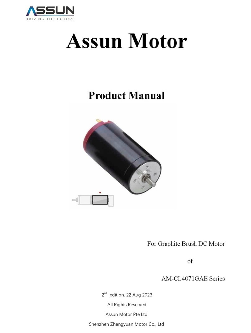
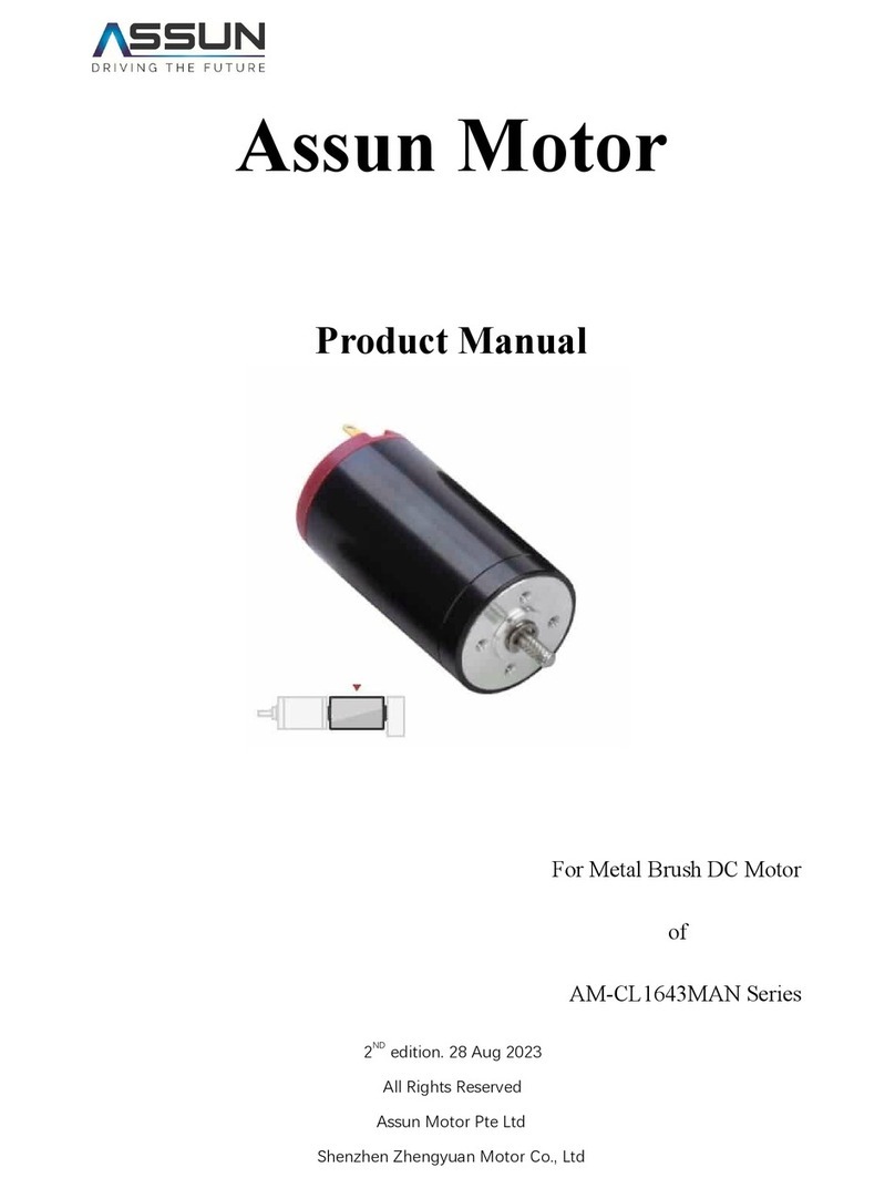
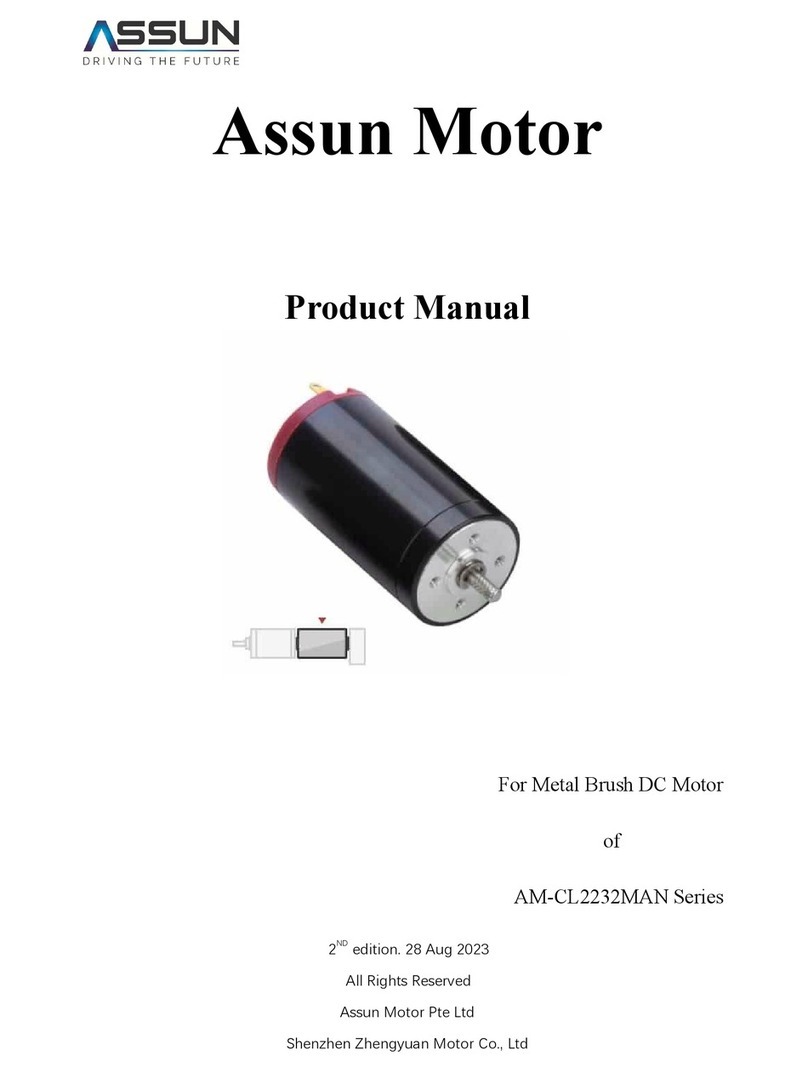
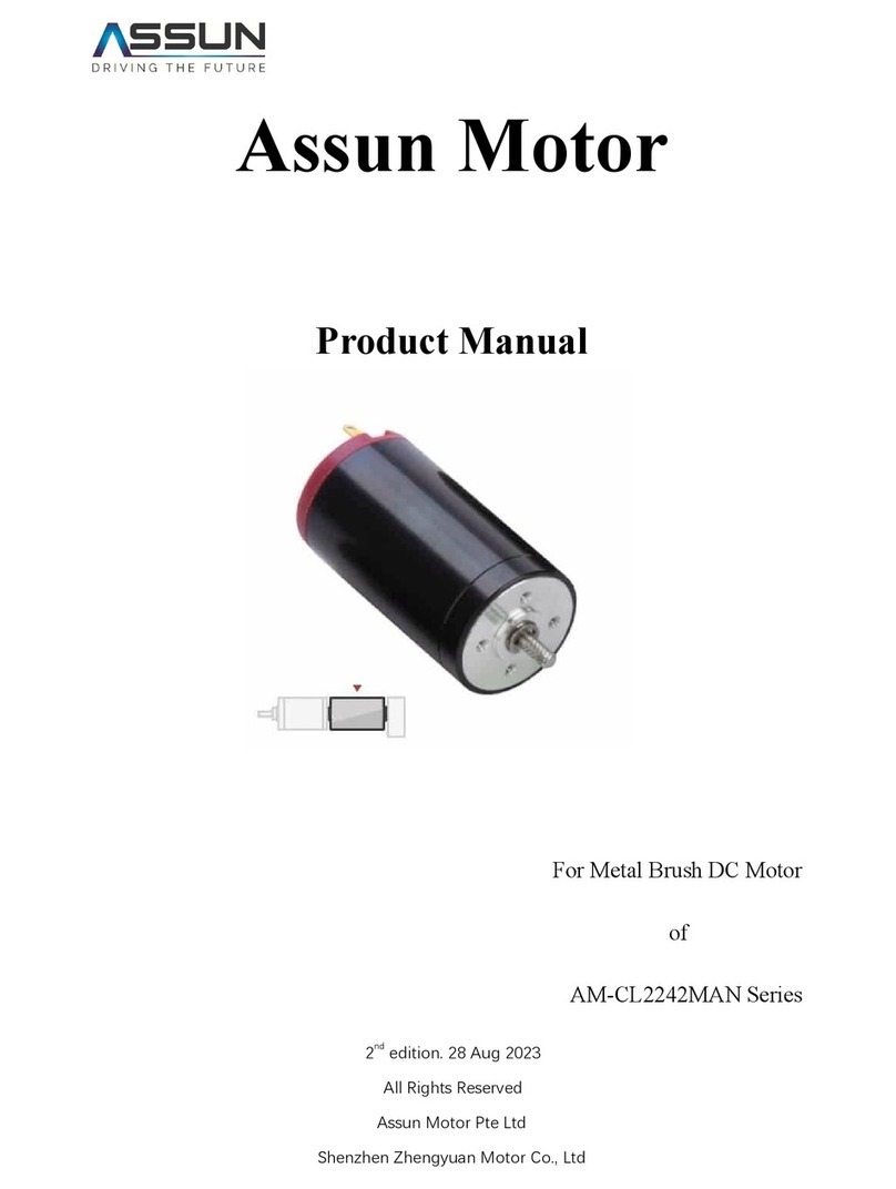
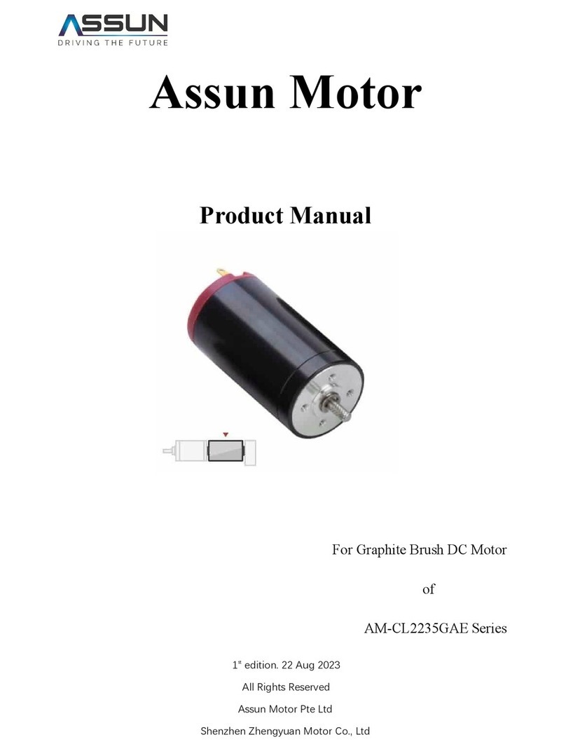
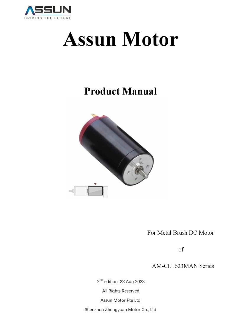
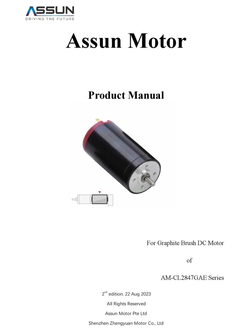
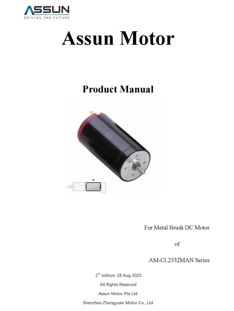
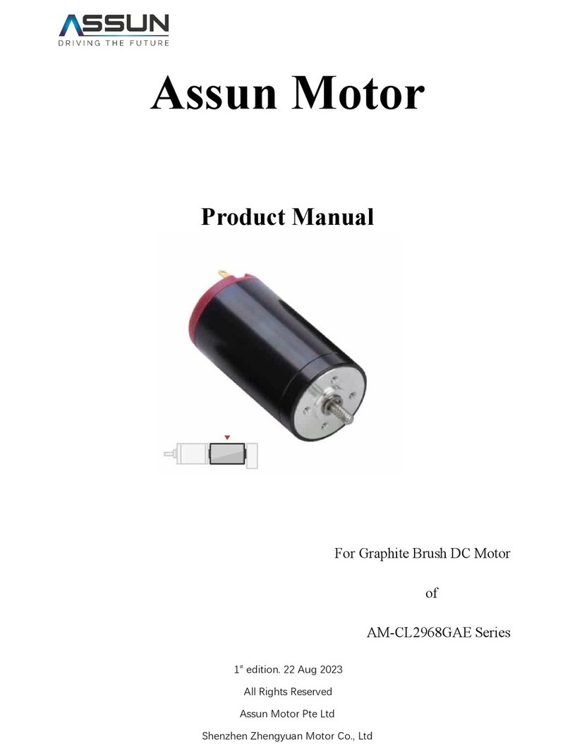
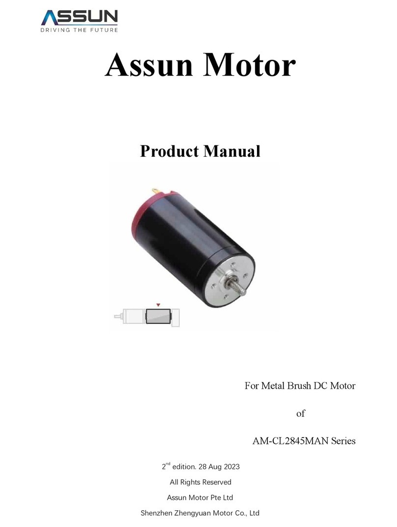
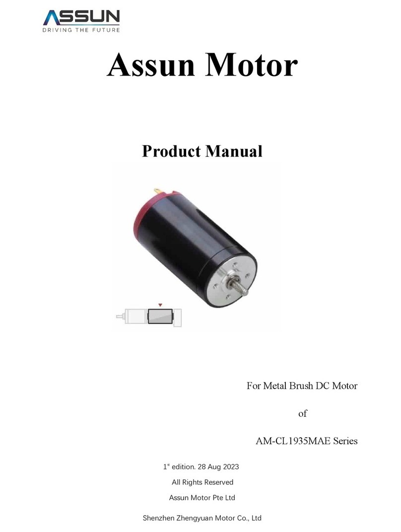
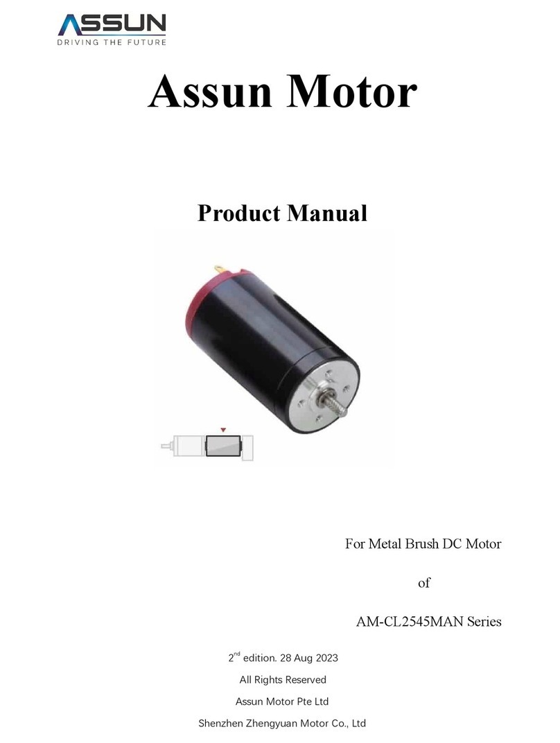
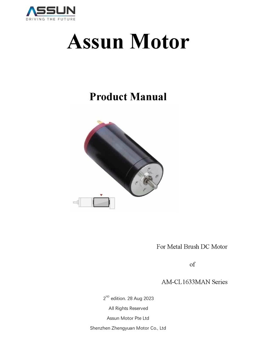
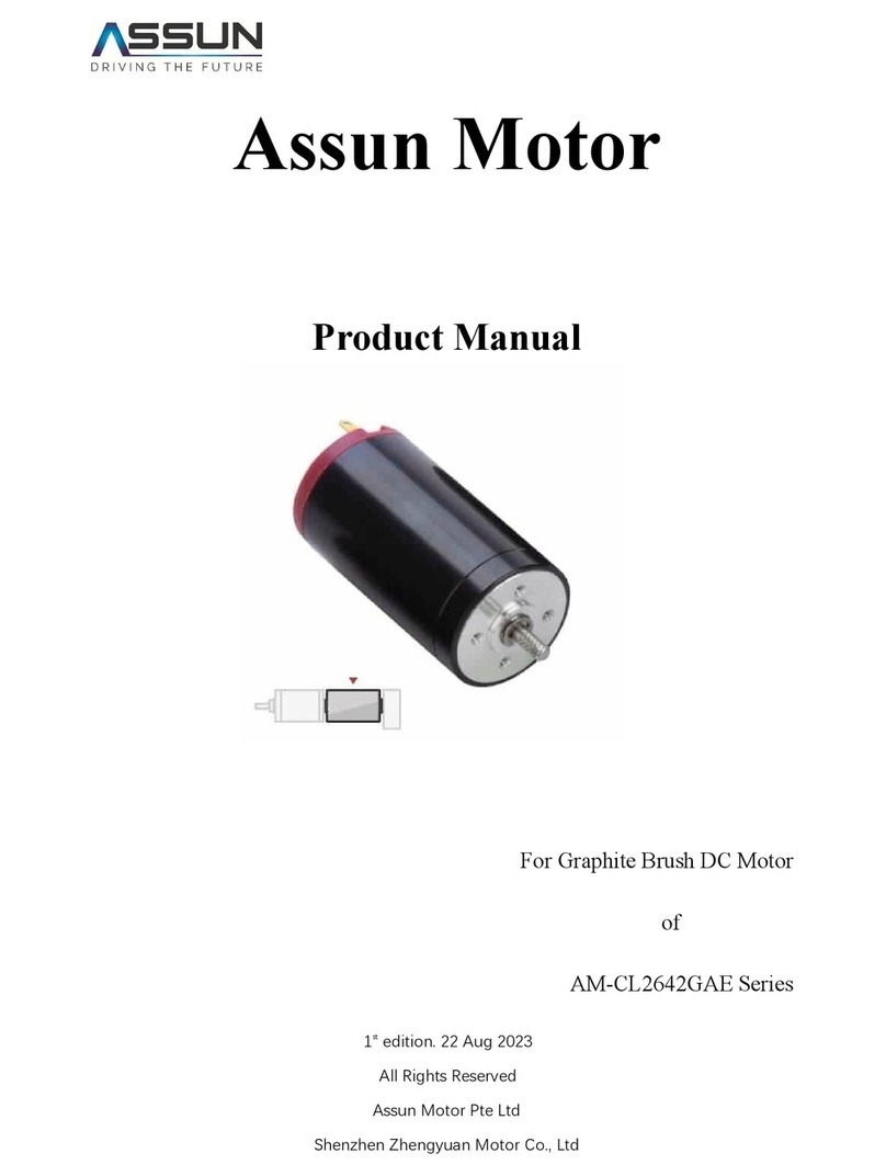
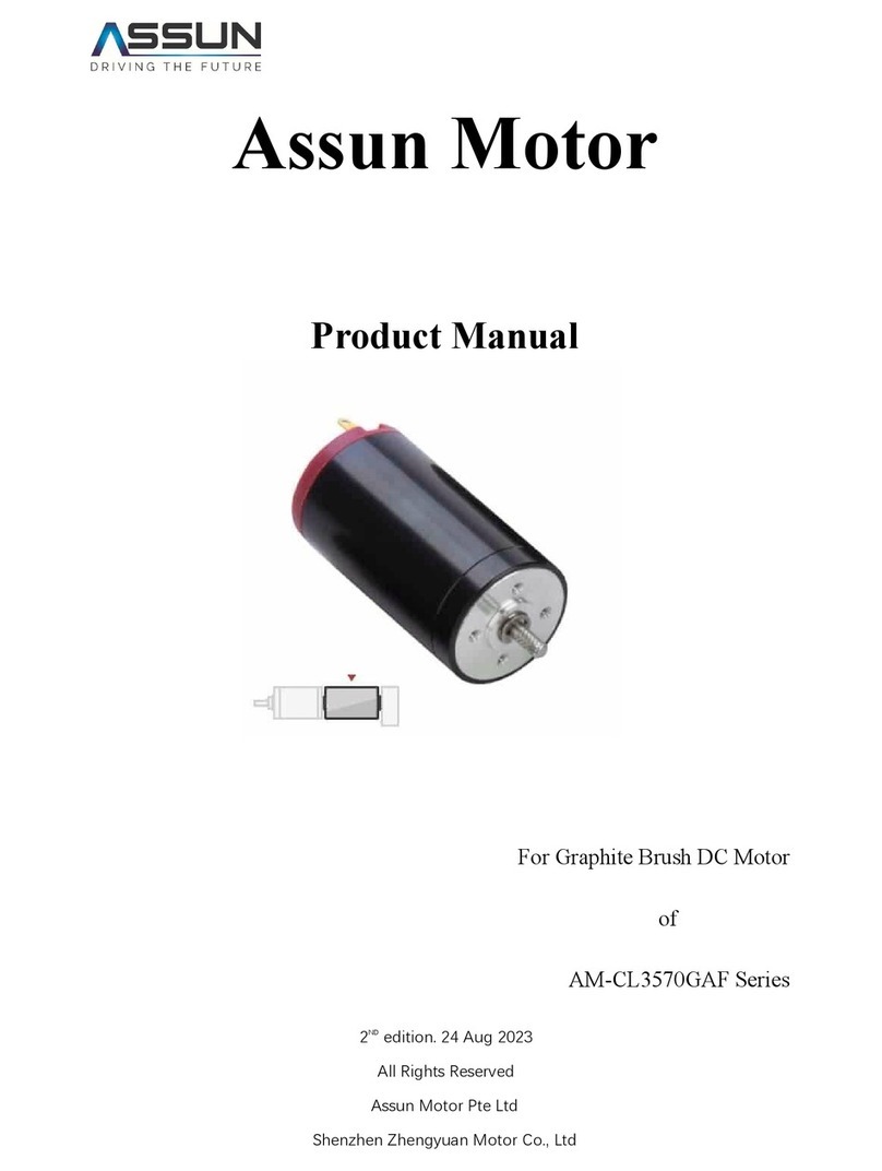
The series of products have two power-connecting metal plates at the rear end, connecting to
the DC power supply positive and negative. Customers could choose to have a rear shaft or not
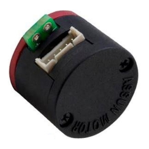
to have a rear shaft. When the motor needs to work with an encoder, the rear shaft is needed to
connect to the encoder. When an encoder is not needed, the motor usually does not have a rear
shaft.
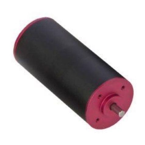
The motor is using ball bearings thus there will be a boss in both the front and back cover. When
connecting to a gearbox or encoder, the customer should consider the boss dimension to comply.
There are threaded holes on the front/back cover for connection to the gearbox/encoder.
Note: The motor power supply should be connected according to the guidance for the motor to
rotate in a Clockwise direction. CW/CCW direction is defined when looking from the front end of
the motor. When the power supply is reversed, the motor will rotate in Counter Clockwise
direction.
Typically we propose to operate the motor in CW direction.
4.1 Motor Installation and Power Connection
The motor must be properly and securely mounted, typically utilizing the threaded holes in the
front cover to fix the motor. It will be proposed to install the motor to metal parts, or installed in
well-ventilated environments for better heat dissipation.
There are two copper plates at the end of the motor and perpendicular to the end cover in default
condition, but when installed with an encoder or used in other space-limiting conditions the
plates will go sideways. The power cable shall be connected to the copper plates according to
the marking on the end cover so that the motor will rotate in the CW direction. If the power
supply is reversed, the motor will rotate in the CCW direction. After the motor is installed, double-
check the rotating direction. Wrong rotating direction using the wrong cable connection may
damage the relevant equipment.
