ASTEL TR 808LP User manual

TR 808LP
VIDEO TWISTED-PAIR RECEIVER
OPERATING INSTRUCTIONS v1.0

2
CONTENTS
Preface ........................................................................................................................................................3
Features.......................................................................................................................................................3
Block diagram..............................................................................................................................................3
Principle of operation...................................................................................................................................3
Controls and connectors..............................................................................................................................4
Connections.................................................................................................................................................5
Installation....................................................................................................................................................6
Appearance .................................................................................................................................................8
Specifications...............................................................................................................................................8
SAFETY PRECAUTIONS
In order to prevent any fatal accidents caused by
misoperation or mishandling of the video twisted-
pair receiver, be fully aware of all the following
precautions.
WARNING:
THIS APPARATUS MUST BE EARTHED
This unit is produced to comply with Directives
93/68/EEC (IEC Publ.65) and 89/336/EEC.
Due to continuous product improvement all specifications and design are subject to change without notice.

3
PREFACE
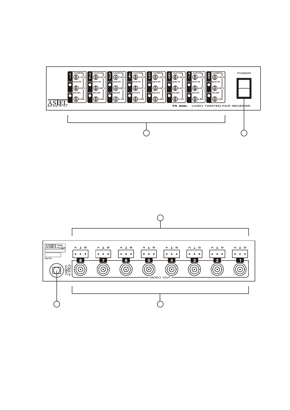
The video twisted-pair receiver TR 808LP is a
eight-channel correction amplifier with eight
symmetrical inputs and eight standard
asymmetrical video outputs. Standard BNC type
output connectors enables the TR 808LP to be
used with other CCTV amplifiers, switchers,
cameras, monitors and digital video recorders All
adjustments are available with only three trimmers
to adjust linear and high frequency gain. There
are green and red LED which indicate the power-
on and the video signal error in the video input of
the receiver.
FEATURES
8 symmetrical video inputs
8 asymmetrical video outputs
simple adjustments
over-voltage protection
rack mountable using optional rack mount kit
PRECAUTIONS
Use only the power source specified on the
rating label located on rear of the cabinet.
When not using this unit for a long period of
time, or when cleaning it, be sure to disconnect
the power plug from the AC outlet.
Do not drop metallic parts through slots. This
action could permanently damage this unit. Do
turn power off immediately and refer servicing to
qualified service personnel.
Avoid using this unit under the following
conditions:
-in extremely hot, cold or humid places,
-in dusty places,
-near appliances generating strong magnetic
fields,
-in places subject to direct sunlight, and
-in badly ventilated places.
Unplug this unit from the AC outlet and refer
servicing to qualified service personnel under
the following conditions:
-when the power cord is frayed or plug is
damaged
-if the unit does not operate normally following
the operating instructions
-if the unit has been dropped or the cabinet has
been damaged
-when the unit exhibits a distinct change in
performance.

4
CONTROLS AND CONNECTORS
FRONT PANEL
(1) CHANNELS 1 - 8
Trimmers and LEDs for adjustments and
indications.
HF2 – the second high-frequency gain adjustment
trimmer.
HF1 – the first high-frequency gain adjustment
trimmer.
LIN – the linear gain adjustment trimmer.
POWER LED – the green LED as power-on
indicator.
ERROR LED – the red LED for video signal error
indication.
(2) POWER
Switch to turn the power on / off - lights in the
power on position.
REAR PANEL
(1) POWER SUPPLY
Power cord.
(2) VIDEO INPUTS 1-8
Eight video input terminal block connectors to
connect twisted-pair cables.
(3) VIDEO OUTPUTS 1-8
Eight standard BNC video output connectors.
1
100-240 VA C 50-60Hz 40W
2
3
2
1

5
CONNECTIONS
Be sure to disconnect the power plug from the
AC outlet before connecting to other
equipment.
Also refer to the instruction manual of the
equipment to be connected.
100-240 VAC 50- 60Hz 40 W
MON MON
DVR
ACMAINS
VIDEO
TWISTED-PAIR
TRANSMITTER
VIDEO
TWISTED-PAIR
TRANSMITTER
VIDEO
TWISTED-PAIR
TRANSMITTER
CAM CAM CAM

6
INSTALLATION
The unit is suitable to use CAT 5 or other UTP (Unshielded Twisted Pair) cables, where is possible to
connect one or more units and enable to pass more than one video signal through the same cable.
(1) Connect the power plug.
(2) Connect the video monitor to the BNC video output connector.
(3) Connect the twisted-pair cable to the video input terminal block connector.
(4) Switch-on the unit.
POWER LED (green) lights, power supply is switched-on.
If there is a video signal at the input, ERROR LED (red) doesn’t light.
(5) Switch-on the video monitor.
(6) Set the correct output video signal (1 Vpp) - trimmer LIN.
(7) Do the adjustment of high frequencies with trimmer HF1.
(8) Do the fine adjustment of high frequencies with trimmer HF2.
(9) Correct the output video signal (1 Vpp) - trimmer LIN.
(10) If there is too much noise in the signal, set the pre-emphasis to 10 dB in the video twisted-pair
transmitter and repeat the adjustments from step (6) to (9).
Maximum distances (CAT 5 UTP Cable) between different models of video twisted-pair transmitters and
receivers:
Model TT 101 TT 101S TTP 101 TTR 101 TTR 202 TTM 101 TTM 101C
TR 101 1600 1600 1800 1600 1600 1800 1800
TR 101L 1500 1500 1500 1500 1500 1500 1500
TR 101LS 1500 1500 1500 1500 1500 1500 1500
TRP 101 1600 1600 1800 1600 1600 1800 1800
TRP 101L 1500 1500 1500 1500 1500 1500 1500
TR 404L 1500 1500 1500 1500 1500 1500 1500
TR 404LP 1500 1500 1500 1500 1500 1500 1500
TR 808L 1500 1500 1500 1500 1500 1500 1500
TR 808LP 1500 1500 1500 1500 1500 1500 1500
TR 1616L 1500 1500 1500 1500 1500 1500 1500
TR 1616LP 1500 1500 1500 1500 1500 1500 1500
TRR 101 1600 1600 1800 1600 1600 1800 1800
TRR 101L 1500 1500 1500 1500 1500 1500 1500
TRR 202L 1500 1500 1500 1500 1500 1500 1500
TRM 101 850 850 900 850 850 900 900
TRM 101C 850 850 900 850 850 900 900

7
Model TT 404 TT 404P TT 808 TT 808P TT 1616 TT 1616P
TR 101 1600 1600 1600 1600 1600 1600
TR 101L 1500 1500 1500 1500 1500 1500
TR 101LS 1500 1500 1500 1500 1500 1500
TRP 101 1600 1600 1600 1600 1600 1600
TRP 101L 1500 1500 1500 1500 1500 1500
TR 404L 1500 1500 1500 1500 1500 1500
TR 404LP 1500 1500 1500 1500 1500 1500
TR 808L 1500 1500 1500 1500 1500 1500
TR 808LP 1500 1500 1500 1500 1500 1500
TR 1616L 1500 1500 1500 1500 1500 1500
TR 1616LP 1500 1500 1500 1500 1500 1500
TRR 101 1600 1600 1600 1600 1600 1600
TRR 101L 1500 1500 1500 1500 1500 1500
TRR 202L 1500 1500 1500 1500 1500 1500
TRM 101 850 850 850 850 850 850
TRM 101C 850 850 850 850 850 850
The maximum distance can also be increased by using the cable with lower cable attenuation – like PE
cable (A-2Y (L) 2Y)
SPECIFICATIONS
Video input : 8, 0.12 - 2Vpp, terminal block
Video output : 8, 1Vpp, 75 , BNC
Input impedance : 120
Freq. response : 50 Hz - 5 MHz (-3 dB)
Linear gain adjustment : -3 dB - +20 dB (LIN)
HF1 gain adjustment : max. +24 dB (HF1)
HF2 gain adjustment : max. +20 dB (HF2)
Input protection : noble-gas filled surge arrester, zener diodes
Indicators : LED green - power-on
LED red - video-signal-error
Power requirement : 100-240VAC, 50-60Hz
Power consumption : 40W max.
Dimensions : 216(W) x 44(H) x 240(D) mm
Weight : 2.0 kg

8
ASTEL d.o.o., Dutovlje 138, 6221 Dutovlje, Slovenia
Tel: +386 5 7310771, +386 5 7310772
Fax:+386 5 7310789
E-mail: [email protected]
Web: www.astel-cctv.com
This manual suits for next models
1
Table of contents
Other ASTEL Receiver manuals