Ten-Tec RX-340 User manual

TECHNICAL MANUAL
OPERATION, MAINTENANCE, INSTALLATION INSTRUCTIONS
AND ILLUSTRATED PARTS BREAKDOWN
HF DSP RECEIVER
MODEL RX-340
TEN-TEC, INC.
1185 DOLLY PARTON PARKWAY
SEVIERVILLE, TN 37862
THIS MANUAL WAS PREPARED IN ACCORDANCE WITH MIL-HDBK- 1221

TEN-TEC RX340 AUX/AUDIO OUTPUT PINS
Wiring for 15 pin male D type plug;
Pin 1 - Ground
Pin 2 - Mono audio output (AC coupled audio. Decoupled through a pair of back to back
33 µf capacitors).
Pin 3 - Audio line output B
Pin 4 - Audio line output BCT
Pin 5 - Audio line output B+
Pin 6 - Audio line output A
Pin 7 - Audio line output ACT
Pin 8 - Audio line output A+
Pin 9 - Ground
Pin 10 - Mono audio output (DC coupled audio. Resistive connection straight from audio
amplifier).
Pin 11 - Mute
Pin 12 - User function
Pin 13 - User function
Pin 14 - User function
Pin 15 - User function
For most normal audio output applications use the mono AC coupled audio output on pin
2 with pin 1 as ground. This will give up to 10 mW output into a 600 ohm load.
For more specific applications where the full audio frequency bandwidth is required (i.e.
certain data decoding uses), use the mono DC coupled audio output on pin 10. Do not
use this output to connect to any equipment with any appreciable amount of DC voltage
floating on its input connection. Output is 10 mW into 600 ohm.
Two balanced line outputs are provided giving a 0 dBm level / 600 ohm. Line output A
and B give the same audio output in all modes except ISB where A gives the USB signal
and B the LSB signal.
These two outputs have their own independent output transformers so arc isolated
from each other and from any ground connection.
For most purposes (e.g., for a stereo tape recorder), wire the center and ground of
one RCA/phono to B+ and B- respectively for one channel and the center and ground of
another to A+ and A- respectively.
In addition, a transformer centre tap is provided on each line output (ACT and
BCT) where balanced line output is required.
Refer to manual sections: 1-4 for interface connections.
3-4 (fig 3-5) for connections.
10-33/34 for circuit wiring details.

RECORD OF CHANGES
CHANGE
NO. DATE TITLE OR BRIEF DESCRIPTION ENTERED BY

WARNING
HIGH VOLTAGE
is used in the operation of this equipment.
DEATH ON CONTACT
may result if personnel fail to observe safety precautions.
Learn the areas containing high voltage within the equipment.
Be careful not to contact high voltage connections when installing,
operating or maintaining this equipment.
Before working inside the equipment, turn power
and ground points of high potential OFF before touching them.

TABLE OF CONTENTS
PARAGRAPH PAGE
LIST OF ILLUSTRATIONS
v
LIST OF TABLES
vii
INTRODUCTION
viii
1. GENERAL INFORMATION
1-1 PURPOSE AND FUNCTION 1-1
1-2 SPECIFICATIONS 1-5
1-3 ENVIRONMENTAL CONDITIONS 1-9
1-4 MECHANICAL 1-10
1-5 EQUIPMENT/PARTS SUPPLIED 1-11
2. PREPARATION FOR USE AND INSTALLATION
2-1 UNPACKING AND INSPECTION 2-1
2-2 MOUNTING 2-1
2-3 POWER 2-1
2-4 ANTENNA 2-1
2-5 IF OUT 2-1
2-6 SIG MON 2-1
2-7 1ST MIXER OUT 2-1
2-8 2ND MIXER OUT 2-1
2-9 EXT REFERENCE 2-1
2-10 RS-232 2-2
2-11 LINE A 2-2
2-12 LINE B 2-2
2-13 AUDIO 2-2
2-14 DC DOUPLED AUDIO 2-2
2-15 AUX OUTPUT 2-2
2-16 MONO HEADPHONE 2-2
2-17 ISB HEADPHONE 2-2
2-18 CHASSIS GROUND 2-2
3. GENERAL THEORY OF OPERATION
3-1 INTRODUCTION 3-1
3-2 PRESELECTOR (81878) 3-1
3-3 PREAMP/ATTN 3-1
3-4 FIRST MIXER (81823) 3-6
3-5 SECOND MIXER/THIRD LOCAL OSCILLATOR (81817) 3-6
3-6 CONVERTER I/O BOARD (81790) 3-7
3-7 FIRST LO SYNTHESIZER (81772) 3-8
3-8 SECOND LOCAL OSCILLATOR (81772) 3-8
i

TABLE OF CONTENTS continued
PARAGRAPH PAGE
3. GENERAL THEORY OF OPERATION continued
3-9 10 MHz REFERENCE OSCILLATOR (81772) 3-9
3-10 DSP/CPU (81807) 3-9
3-11 FRONT PANEL CPU (81819) 3-10
3-12 KEYPAD BOARD (81820) 3-11
3-13 LOGIC BOARD ↔CPU INTERCONNECTIONS 3-11
4. LOCAL OPERATION
4-1 INTRODUCTION 4-1
4-2 FRONT PANEL OVERVIEW 4-1
4-3 MAIN TUNING KNOB 4-2
4-4 LOCK BUTTON 4-2
4-5 STEP ←→BUTTONS 4-2
4-6 MODE ←→BUTTONS 4-3
4-7 BITE BUTTONS 4-3
4-8 ↑/+ AND ↓/- BUTTONS 4-3
4-9 ATTN/PREAMP BUTI’ON 4-4
4-10 MANUAL GAIN KNOB 4-4
4-11 REMOTE BUTTON 4-4
4-12 ISB SPEAKER SOURCE BUTTON 4-5
4-13 SPEAKER KNOB 4-5
4-14 PHONES KNOB 4-5
4-15 AUXILIARY PARAMETER OVERVIEW 4-5
4-16 BANDWIDTH (BW) BUTTON 4-6
4-17 BEAT FREQUENCY OSCILLATOR (BFO) BUTTON 4-7
4-18 PASSBAND (PBT) BUTTON 4-8
4-19 DUMP BUTTON 4-9
4-20 AUTOMATIC GAIN CONTROL (AGC) BUTTON 4-9
4-21 NOTCH BUTTON 4-10
4-22 SQUELCH (SQL) BUTTON 4-11
4-23 NOISE BLANKER (NB) BUTTON 4-12
4-24 OPT-1 BUTTON 4-12
4-25 OPT-2 BUTTON 4-12
4-26 MEMORY/SCAN OVERVIEW 4-12
4-27 STORE THE CURRENT OPERATING FREQUENCY IN A
SPECIFIED CHANNEL (0-100)
4-13
4-28 STORE THE CURRENT OPERATING FREQUENCY IN THE
LOWEST EMPTY CHANNEL NUMBER
4-14
4-29 STORE THE CURRENT OPERATING FREQUENCY IN THE
SCRATCHPAD MEMORY
4-15
4-30 TO RECALL A SPECIFIC CHANNEL FROM MEMORY 4-15
ii

TABLE OF CONTENTS continued
PARAGRAPH PAGE
4. LOCAL OPERATION continued.
4-31 USING THE SCROLL FUNCTION TO PREVIEW THE
CHANNEL MENU
4-16
4-32 USING THE TUNE FUNCTION TO ACCESS
FREQUENCIES FROM THE CHANNEL MENU
4-17
4-33 CLEARING OCCUPIED CHANNELS TO CREATE EMPTY
CHANNELS
4-18
4-34 SCAN MODE PRIMER 4-18
4-35 TO SETUP A PSCAN (PROGRAMMED F1→F2)
FREQUENCY SWEEP
4-20
4-36 INITIATING SCAN 4-23
4-37 FREQUENCY LOCKOUTS 4-23
4-38 TO SET UP A MEMORY/SCAN FREQUENCY SWEEP 4-25
4-39 INITIATING MSCAN 4-28
4-40 LOCKING OUT MSCAN CHANNELS 4-29
4-41 PAUSING AND RESTARTING SCANS 4-29
5. DETAILED OPERATING INSTRUCTIONS
5-1 MULTI-DROP NETWORK 5-1
5-2 RECEIVER CONTROL 5-2
5-3 RECEIVER RESPONSE COMMANDS 5-3
5-4 RECEIVER CONTROL COMMANDS 5-3
5-5 RX-340 RECEIVER MEMORY COMMAND SET 5-9
5-6 RX-340 RECEIVER QUERY COMMAND SET 5-9
5-7 RX-340 RECEIVER BITE 5-11
5-8 DSP DATA OUTPUT 5-11
5-9 SCAN OPERATION 5-12
5-10 SECURITY FUNCTIONS 5-14
6. MAINTENANCE INSTRUCTIONS
6-1 INTRODUCTION 6-1
6-2 CLEANING AND LUBRICATION 6-1
6-3 TROUBLESHOOTING 6-1
6-4 INSPECTION 6-1
6-5 PERFORMANCE VERIFICATION TEST FOR MODEL RX-
340
6-1
6-5.1 TEST EQUIPMENT REQUIRED FOR MODEL RX-340 6-1
6-5.2 FUNCTIONAL TESTS FOR MODEL RX-340 6-2
7. PREPARATION FOR SHIPMENT OR STORAGE
7-1 PREPARATION FOR RESHIPMENT 7-1
7-2 PREPARATION FOR STORAGE 7-1
iii

TABLE OF CONTENTS continued
PARAGRAPH PAGE
8. SINGLE SOURCE PARTS LIST
8-1 INTRODUCTION 8-1
9. FINAL ASSEMBLY MODEL RX-340
9-1 INTRODUCTION 9-1
10. ILLUSTRATIONS AND PARTS LIST
10-1 INTRODUCTION 10-1
iv

LIST OF ILLUSTRATIONS
FIGURE PAGE
1-1 RX-340 FRONT VIEW 1-3
1-2 RX-340 REAR VIEW 1-4
3-1 RX-340 TOP VIEW 3-2
3-2 RX-340 FRONT PANEL REAR VIEW 3-3
3-3 RX-340 BOTTOM VIEW 3-4
3-4 RX-340 INTERCONNECT DIAGRAM 3-5
5-1 CONNECTION DIAGRAM 5-2
5-2 CONFIGURATION DIAGRAM 5-15
5-3 SERIAL/PARALLEL INTERFACE 5-16
5-4 DB-25 PIN ASSIGNMENTS 5-17
10-1 MODEL RX-340 BLOCK DIAGRAM 10-2
10-2 LOGIC BOARD BLOCK DIAGRAM 10-3
10-3 SYNTHESIZER BLOCK DIAGRAM 10-4
10-4 81878 CIRCUIT TRACE TOP 10-5
10-5 81878 CIRCUIT TRACE BOTTOM 10-6
10-6 81878 RX PRESELECTOR TOP COMPONENT LAYOUT 10-7
10-7 81878 RX PRESELECTOR BOTTOM COMPONENT LAYOUT 10-8
10-8 81878 RX PRESELECTOR SCHEMATIC 10-9
10-9 81823 SMD 1ST MIXER TOP CIRCUIT TRACE 10-13
10-10 81823 SMD 1ST MIXER BOTTOM CIRCUIT TRACE 10-14
10-11 81823 SMD 1ST MIXER TOP COMPONENT LAYOUT 10-15
10-12 81823 SMD 1ST MIXER BOTTOM COMPONENT LAYOUT 10-16
10-13 81823 SMD 1ST MIXER SCHEMATIC 10-17
10-14 81817 SMD 2ND MIXER/IF TOP CIRCUIT TRACE 10-19
10-15 81817 SMD 2ND MIXER/IF BOTTOM CIRCUIT TRACE 10-20
10-16 81817 SMD 2ND MIXER/IF TOP COMPONENT LAYOUT 10-21
10-17 81817 SMD 2ND MIXER/IF BOTTOM COMPONENT LAYOUT 10-22
10-18 81817 SMD 2ND MIXER/IF SCHEMATIC 10-23
10-19 81790 SMD CONVERTER I/O TOP CIRCUIT TRACE 10-26
10-20 81790 SMD CONVERTER I/O BOTTOM CIRCUIT TRACE 10-27
10-21 81790 SMD CONVERTER I/O BOARD TOP COMPONENT
LAYOUT
10-28
10-22 81790 SMD CONVERTER I/O BOARD BOTTOM
COMPONENT LAYOUT
10-29
10-23 81790 SMD CONVERTER I/O BOARD SCHEMATIC 10-30
10-24 81772 TCXO TOP CIRCUIT TRACE - SYNTHESIZER 10-33
10-25 81772 TCXO INNER CIRCUIT TRACE - SYNTHESIZER 10-34
10-26 81772 TCXO BOTTOM CIRCUIT TRACE - SYNTHESIZER 10-35
10-27 81772 TCXO TOP COMPONENT LAYOUT - SYNTHESIZER 10-36
10-28 81772 TXCO BOTTOM COMPONENT LAYOUT-
SYNTHESIZER
10-37
v

LIST OF ILLUSTRATIONS continued
FIGURE PAGE
10-29 81772 TCXO SYNTHESIZER SCHEMATIC 10-38
10-30 81824 POWER SUPPLY FILTER TOP CIRCUIT TRACE 10-42
10-31 81824 POWER SUPPLY FILTER BOTTOM CIRCUIT TRACE 10-43
10-32 81824 POWER SUPPLY FILTER COMPONENT LAYOUT 10-44
10-33 81824 POWER SUPPLY FILTER SCHEMATIC 10-45
10-34 81807 DSP/CPU TOP CIRCUIT TRACE 10-47
10-35 81807 DSP/CPU BOTTOM CIRCUIT TRACE 10-48
10-36 81807 DSP/CPU COMPONENT LAYOUT 10-49
10-37 81807 DSP/CPU SCHEMATIC (page 1 of 2) 10-50
10-38 81807 DSP/CPU SCHEMATIC (page 2 of 2) 10-51
10-39 81819 FRONT PANEL CPU TOP CIRCUIT 10-53
10-40 81819 FRONT PANEL CPU BOTTOM CIRCUIT 10-54
10-41 81819 FRONT PANEL CPU TOP COMPONENTS 10-55
10-42 81819 FRONT PANEL CPU BOTTOM COMPONENTS 10-56
10-43 81819 FRONT PANEL CPU SCHEMATIC 10-57
10-44 81820 KEYPAD BOARD TOP CIRCUIT 10-61
10-45 81820 KEYPAD BOARD BOTTOM CIRCUIT 10-62
10-46 81820 KEYPAD BOARD TOP COMPONENTS 10-63
10-47 81820 KEYPAD BOARD BOTTOM COMPONENTS 10-64
10-48 81820 KEYPAD BOARD SCHEMATIC 10-65
vi

LIST OF TABLES
TABLE PAGE
8-1 MODEL RX-340 SINGLE SOURCE PARTS LIST 8-1
8-2 PART MANUFACTURER’S INFORMATION 8-3
9-1 RX-340 MODULES 9-1
9-2 FINAL ASSEMBLY REPLACEABLE PARTS 9-2
10-1 81878 RX PRESELECTOR PARTS LIST 10-11
10-2 81823 1ST MIXER PARTS LIST 10-18
10-3 81817 2ND MIXER/IF PARTS LIST 10-24
10-4 81790 CONVERTER I/O BOARD PARTS LIST 10-31
10-5 81772 SYNTHESIZER PARTS LIST 10-39
10-6 81824 POWER SUPPLY FILTER PARTS LIST 10-46
10-7 81807 DSP/CPU BOARD PARTS LIST 10-52
10-8 81819 FRONT PANEL CPU BOARD PARTS LIST 10-59
10-9 81820 KEYPAD BOARD PARTS LIST 10-67
10-10 RECORD OF CHANGES 10-68
vii

INTRODUCTION
This technical manual provides operation and maintenance instructions for the RX-340
HF DSP Receiver. The manual was prepared in accordance with MIL-HDBK- 1221,
“Department of Defense Handbook for Evaluation of Commercial Off-The-Shelf (COTS)
Manuals.” It is organized into ten chapters along with a Table of Contents, List of
Illustrations, and List of Tables.
Chapter 1 presents general information about the Receiver, which includes functional
capabilities, performance specifications, and physical dimensions. Chapter 2 provides
information concerning the unpacking and initial installation of the receiver. A general
theory of operation is provided in Chapter 3 which describes the functioning of the
Receiver’s individual circuit boards. Chapter 4 provides detailed descriptions of all
front- panel operating controls, plus complete instructions for local operation. Chapter 5
contains information on operation of the multi-drop RS-232 Interface and the Parallel
Data Output. Chapter 6 provides information on maintenance and troubleshooting
measures to be employed at the user’s level. Instructions pertaining to the reshipment or
long term storage are provided in Chapter 7. A detailed list of unique single-source parts
is provided in Chapter 8. In addition, Chapter 8 contains a list of manufacturers for these
parts and their addresses. Chapter 9 provides a listing of replaceable modules and parts.
Chapter 10 contains detailed parts lists for each of the replaceable modules. Chapter 10
also contains schematic diagrams for the electronic circuits.
viii

1-1
GENERAL INFORMATION
1-1 PURPOSE AND FUNCTION: The TEN TEC RX-340 is an all-mode, general-
coverage receiver that delivers military-grade performance at off- the-shelf commercial
pricing. Powerful digital signal processing (DSP) and over 60,000 lines of intensive code
provide a level of performance and flexibility unattainable with conventional analog
circuitry.
The RX-340 may be controlled locally from the front panel, or operated remotely through
a RS-232 interface. Knobs, switches, and displays are arranged ergonomically into four
intuitive control groups. Frequency, Mode, and Tuning Rate are presented in 12.5mm
blue-green fluorescent characters on the receiver’s main alphanumeric display.
Operating frequency is controlled by direct keypad entry or by a weighted main tuning
knob, with continuous coverage from below 50 kHz to 30 MHz. Ten step-tuning rates
are provided (from 1 Hz to 1 MHz) to accommodate a wide range of tuning requirements.
Display resolution is 1 Hz, and frequency stability is ±3 ppm over an operating range of
0-50 degrees C.
In addition to manual tuning, 100 channel memories are provided to retain and recall
operating frequency, mode, and other basic operating parameters. Sophisticated
programmable Memory-Scan (MScan) and F1-F2 frequency-scan (PScan) modes are also
provided, along with up to 100 frequency-lockouts and a rapid-access scratchpad
memory. A two-line alphanumeric display provides continuous presentation of the
receiver’s Memory/Scan status, and a dedicated Memory/Scan knob facilitates menu
management and scan programming.
Signal amplification, filtering, and processing are divided between analog and digital
circuitry. Analog features include 1/2-octave front-end filters, ruggedized balanced
mixers, and triple-conversion design to ensure wide dynamic range and superior rejection
of unwanted signals. A sophisticated multistage Automatic Gain Control (AGC) system
provides 80 dB of control range ahead of the A-to-D converters plus an additional 40 dB
in DSP. A switchable attenuator and preamp expand signal-handling range to over 140
dB.
Digitally-controlled operating parameters include an adjustable, offset beat-frequency
oscillator (BFO), variable passband tuning (PBT), tunable notch filter (Notch), wide-
range squelch (SQL), and a variable noise blanker (NB). An extensive bandwidth (BW)
menu provides 57 standard-shape DSP filters ranging from 100 Hz to 16 kHz, plus an
added selection of fast filters for enhanced reception of delay-critical digital modes such
as SITOR. Three preset AGC rates (Fast, Medium, and Slow) are provided, along with a
unique Program Mode that supports fully-adjustable Attack, Hang, and Decay settings.
A momentary AGC-cancel switch (Dump) instantly restores full receiver sensitivity on
demand. A dedicated two-line alphanumeric display continuously presents operating-
parameter status, and a companion Aux Parameters knob adjusts selected operating
characteristics.

1-2
Detection modes include USB, LSB, ISB, CW, CW1, NBFM, AM, and Synchronous
AM, with selectable sidebands. SAM significantly reduces fading and adjacent-channel
interference on AM signals. Separate headphone and speaker gain controls adjust
listening level (speaker-level audio is routed to a built-in 4-inch speaker and a switchable
external-speaker jack). An AF-channel selector routes upper, lower, or both sideband
channels to the speaker line in ISB and SAM modes. In addition, balanced and
unbalanced line-level outputs are available on the rear panel for remote monitoring.
Signal strength is displayed in either S-units or dBm on a large-scale, 2-1/2-inch analog
meter. Meter sensitivity is automatically compensated when the preamp or attenuator is
activated or manual gain is adjusted.
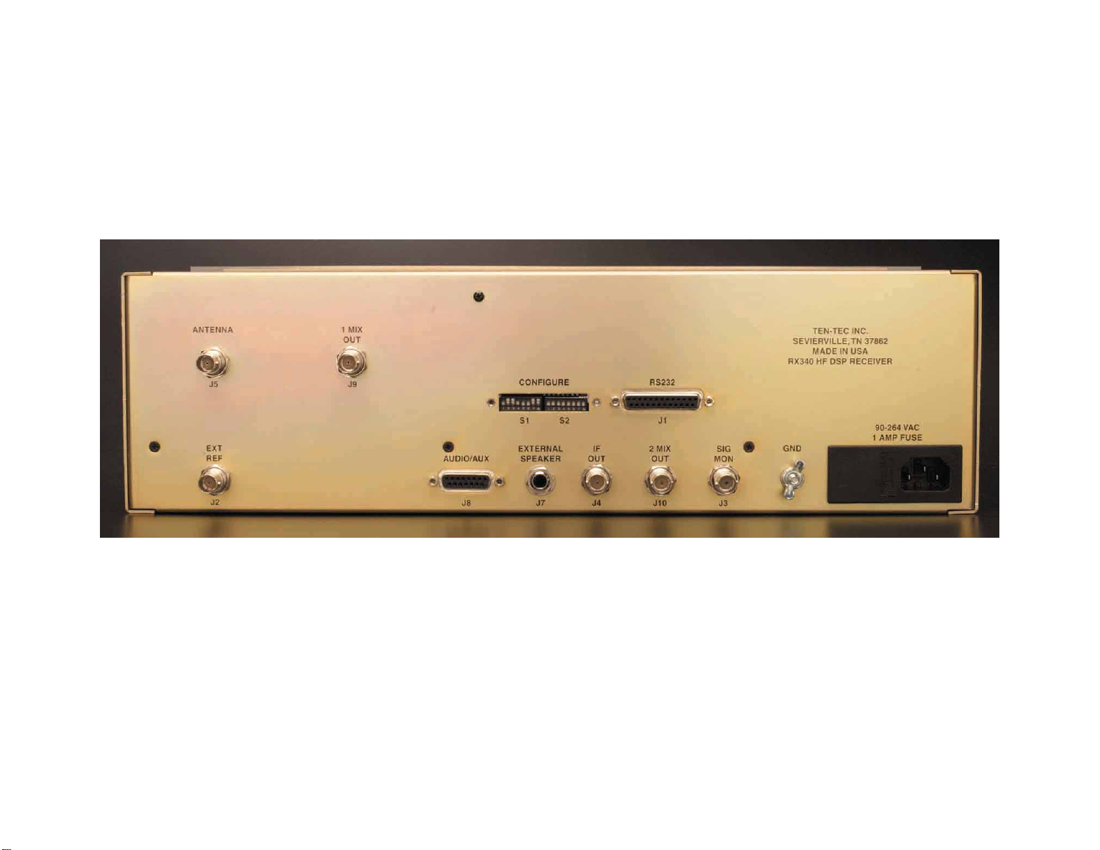
Rear-panel BNC jacks provide inputs for the antenna and external reference oscillator,
plus access to mixer and IF monitoring points. A standard DB-25 jack accepts a Multi-
drop RS-232 line for remote receiver operation. The RX-340’s built-in power supply is
designed for international use, accepting a wide range of voltages and line frequencies.
Conservative engineering, all-SMD circuitry, and rugged mechanical construction ensure
reliable long-term performance.

1-3
RX-340 FRONT VIEW
FIGURE 1-1
1-4
RX-340 REAR VIEW
FIGURE 1-2

1-5
1-2 SPECIFICATIONS:
Applicable from 50 kHz to 30 MHz, unless otherwise stated.
Power Supply: Internal, accepts 48-440 Hz line power, 90-264 VAC. 30 watts nominal.
Frequency Tuning System:
Tuning Range: 50 kHz to 30 MHz at typical sensitivity. Tunable to 0 MHz with
degraded performance.
Tuning Increment: 1 Hz minimum.
Synthesizer lock time: 10 mS nominal.
BFO: Tunable in CW mode only, ±8 kHz, 10 Hz steps. Fixed frequency in SSB and ISB
modes, disabled in AM and FM modes.
Accuracy: All internal oscillators may be locked to either internal or external frequency
standards. The internal reference is adjustable by a continuously variable trimmer,
allowing calibration to any desired accuracy.
Stability (internal standard): ±1 ppm within the 0-50 degrees C operating range.
External Frequency Standard: 1, 2, 5, or 10 MHz ±1 ppm, 500 rnV-2V p-p, high
impedance load. The receiver automatically detects and uses the external standard upon
application, at power-up, or after serial link activity. If the external standard slews far
outside the ± 1 ppm specified, internal circuitry will lose lock until the input returns to
within specification, or will re-lock at the next power-up or serial activity provided the
input is within spec. at a valid reference frequency (1, 2, 5, or 10 MHz). A frequency-
out-of-lock condition is always reported over the serial link. Removal of the external
frequency standard input immediately returns the receiver to the internal standard.
Tuning Method: Local tuning via direct keypad entry, step-arrow keys, or main tuning
knob. Remote timing via multi-drop RS-232.
Frequency Indication: Local indication via main alphanumeric display, 1-Hz resolution.
Remote frequency status reported via the RS-232 serial link.
Interface Connections:
RF Input:
Impedance: 50 ohms nominal
VSWR: 2.5:1 maximum in preselector passband.
Connector: Rear-panel BNC
Protection: Internal Surge Protector
Balanced Line-level Audio Output:
Two 600-ohm Lines
Level: 0 dBm nominal, center-tapped, ungrounded.
Connector: DB-15, 3 pins.

1-6
Function: Upper and Lower sideband audio on separate lines in ISB mode.
Same signal on both lines in other modes.
Single-ended Line-level Audio Outputs:
Level: 10 mW into 600 ohms, one AC- coupled and one DC coupled.
Connector: DA-15, two pins each-line.
Function: Upper, lower, or both sidebands in ISB mode, software configured.
Mono/Stereo Headphones:
Level: 10 mW into 600 ohms per channel, front-panel volume control.
Connector: Front-panel 1/4” stereo phone jack.
Function: Monaural except in ISB, where USB and LSB are split in stereo
phones.
Monaural Speaker-Level Output:
Level: 1.5 W into 4 ohms at 10% THD, 4” internal or external speaker.
Front-panel volume control.
Connector: External, 1/4” rear-panel mono jack.
Function: Monaural monitoring, all modes.
Signal Monitor Delayed AGC:
Frequency: 455 kHz center (inverted, 1 kHz tuning step)
Bandwidth: 16 kHz (-6 dB).
Level: -10 dBm nominal (+1-3 dBm). AGC delayed 40 dB.
Impedance: 50 ohms nominal.
Connector: Rear panel BNC.
IF Output, Post DSP:
Frequency: 455 kHz center (inverted).
Bandwidth: Determined by IF filter selection.
Level: -10 dBm nominal (AGC leveled).
Impedance: 50 ohms nominal.
Connector: Rear panel BNC.
1st Mixer Out, Wideband:
Frequency: 45.455 MHz Center frequency (inverted, 1 kHz tuning step, no
AGC).
Bandwidth: Determined by preselector filter.
Level: -16 dB relative to RX input (Preamp and Attenuator OFF).
Impedance: 50 ohms nominal.
Connector: Rear panel BNC.
2nd Mixer Out, no AGC:
Frequency: 455 kHz center frequency (inverted, 1 kHz tuning steps).
Bandwidth: 16 kHz (-6 dB).
Level: 0 dB rel to RX input (PRESEL/ ATTN OFF).
Impedance: 50 ohms nominal.
Connector: Rear panel BNC.

1-7
Receiver Sensitivity:
Dynamic Range:
Noise Figure (dB) 3rd Order Intercept (dBm)
Mode Typ Max Typ Min
10 dB PREAMP ON 10 14 20 15
PREAMP OFF 17 19 30 25
15 dB ATTEN 32 34 45 40
VLF Sens.,Typ, .3kHz bandwidth preamp OFF.
16 dB SINAD
>500 kHz -116 dBm (.35 µV)
100 kHz -115 dBm (.4 µV)
50 kHz -114 dBm (.45 µV)
20 kHz -107 dBm (1 µV)
15 kHz -104 dBm (1.4 µV)
10 kHz -94 dBm (4.5 µV)
5 kHz -82 dBm (18 µV)
Spurious Responses: All spurious less than -119 dBm equivalent input- preamp ON.
Control Interface:
Standard: Multi-drop RS-232.
Config: Dipswitch programmable, 300 to 19200 baud, 7 or 8 data bits,
even, odd, or no parity.
Connector: DB-25 female.

1-8
Sensitivity By Mode
Preamp OFF Preamp ON
Mode BW SINAD Typical Max Typical Max
AM: (50% Mod
@ 400Hz) 6 kHz 10 dB 103 dBm/
1.6 µV -101 dBm/
2.0 µV -112 dBm/
0.56 µV -108 dBm/
0.9 µV
FM: ( 6kHz dev @
1 kHz) 16 kHz 16 dB -102 dBm/
1.8 µV -100 dBm/
2.2 µV -108 dBm/
0.9 µV -104 dBm/
1.4 µV
USB/LSB/ISB: 3.2 kHz 10 dB
-112 dBm/
0.6 µV -110 dBm/
0.7 µV -119 dBm/
0.25 µV -115 dBm/
0.4 µV
CW: 300 Hz 16 dB
116 dBm/
0.35 µV -114 dBm/
0.45 µV -124 dBm/
0.14 µV -120 dBm/
0.22 µV
Gain Characteristics:
Gain control:
Receiver operates with automatic (AGC) or manual gain control. Manual gain control
reduces receiver gain and increases AGC threshold by up to 120dB.
AGC:
Range: 90 dB minimum
Threshold: 3 µV typical
Attack Time: 15 mS typical, to within ±3dB of 20 dB step.
Release Time:
MODE ATTACK (dB/ms) HANG (sec) DECAY (dB/sec.)
FAST 0.8 0 1200
MEDIUM 0.8 0 100
SLOW 0.8 0 25
PROGRAMMABLE 0.01-1.0 0.01-99.9 0.01-99.9
Manual AGC:
Range: 120 dB. Controlled through the Front Panel or RS-232 interface.
Attack/Release Times: Limited only by RS-232 serial transfer rate.
Programmable AGC:
Setting Ranges:
Attack: 0.01-1.0 dB/ms
Hang: 0.01-99.9 seconds
Decay: 0.01-99.9 dB/s
Table of contents
Other Ten-Tec Receiver manuals


