7
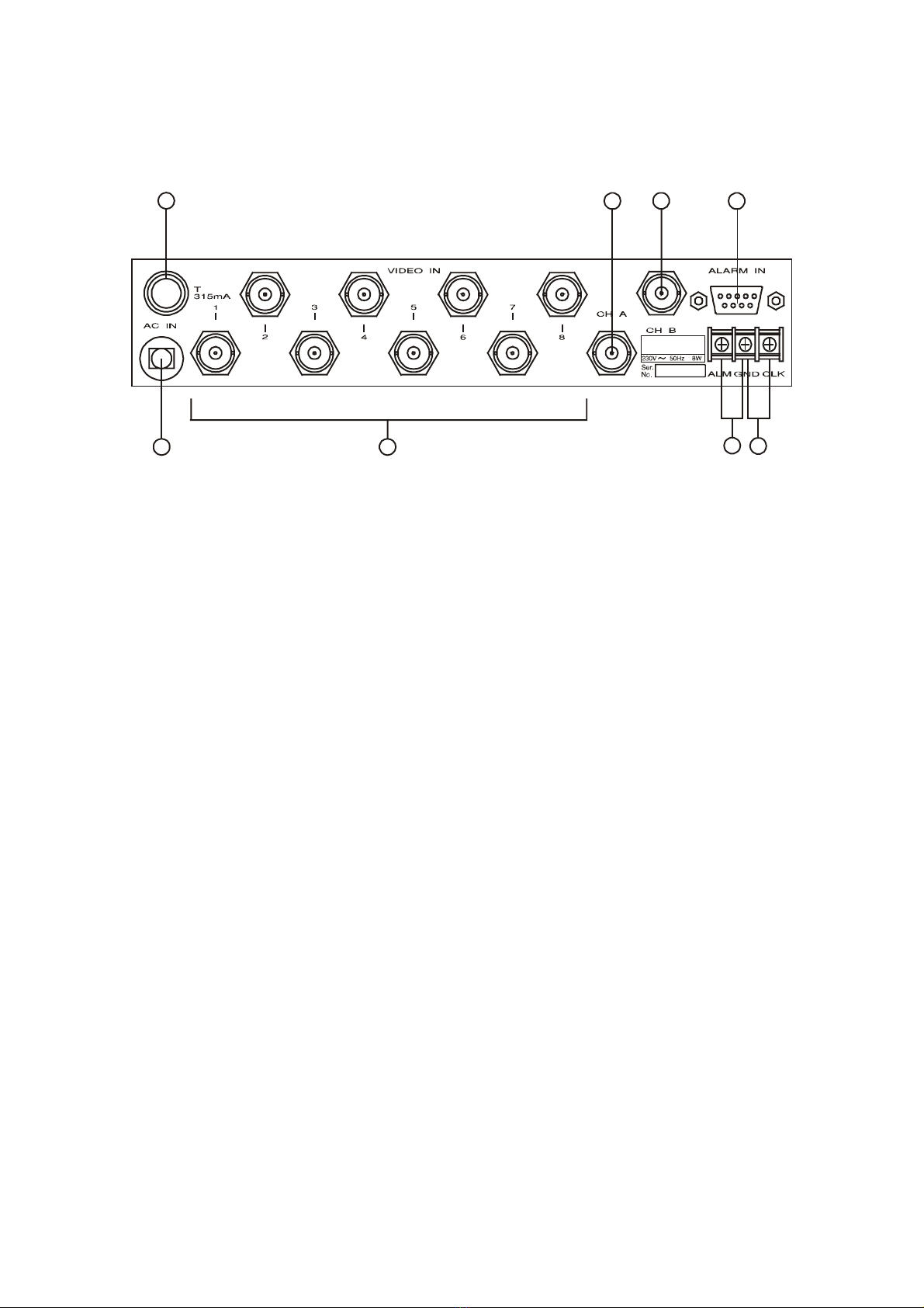
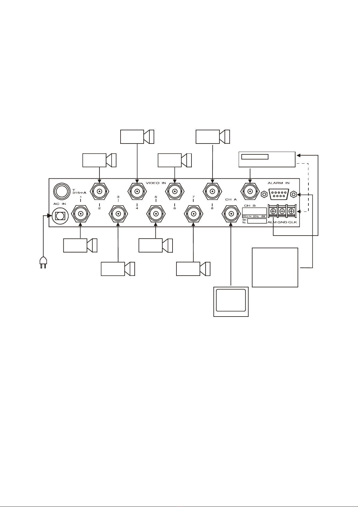
ALARM / REMOTE CONTROL CONNECTION
Connection diagram:
Notes:
•Negative triggering - all alarm switches must
be opened, in case of alarm they are closed.
•Positive triggering - all alarm switches must be
closed, in case of alarm they are opened.
Notes:
• T1 - start/stop key
• T2 - manual scan key
VCR-CLOCK CONNECTION
The VCR-CLK input is a standard TTL negative
triggered input (5V to 0V)
PCB
5V 12V
J102
Note:
•If the VCR CLOCK pulse is 12V, set the
jumper J102 to 12V position.
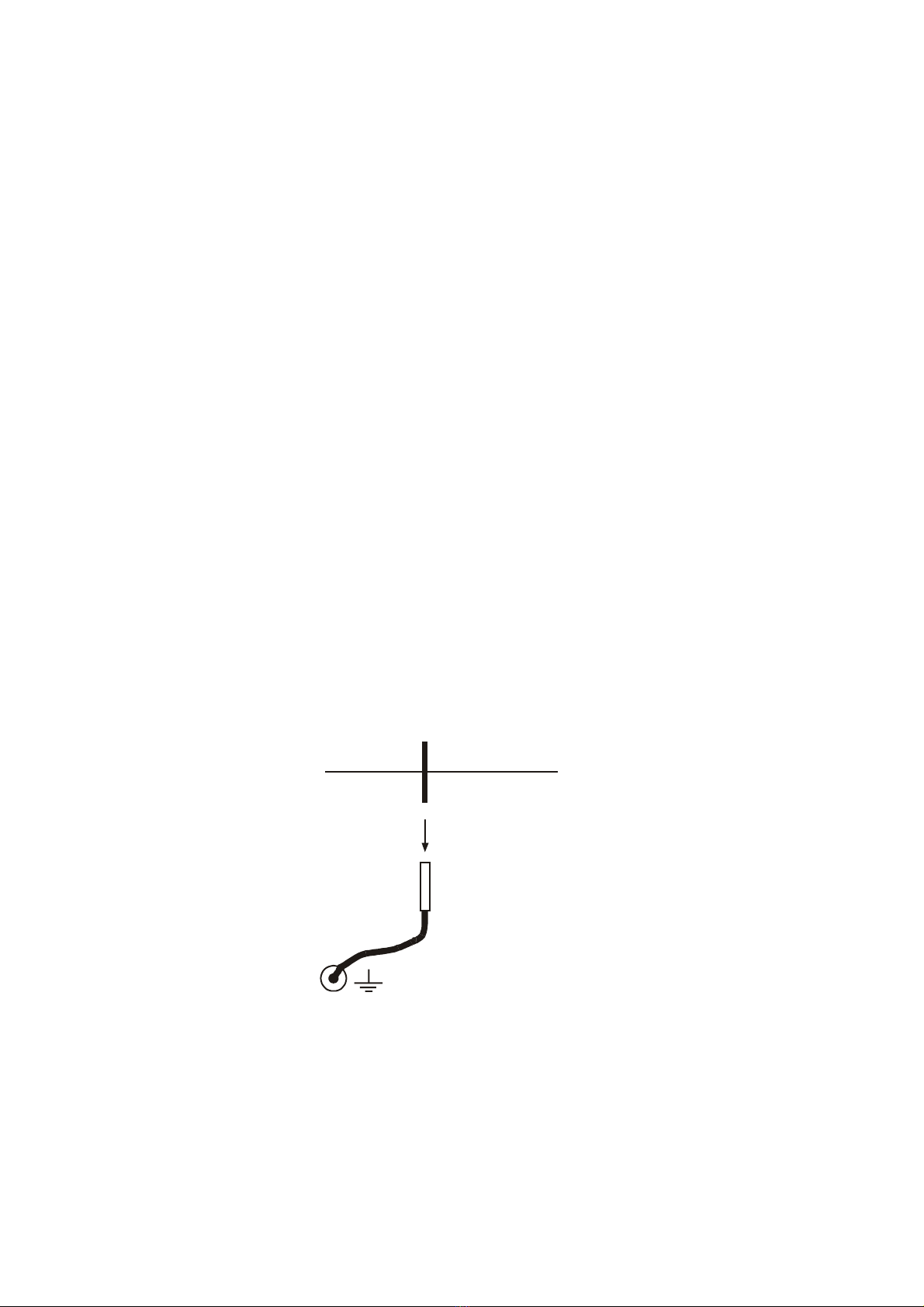
VERTICAL INTERVAL
SWITCHING
This unit includes an electronic circuit which
allows smooth switchings without picture roll or
flutter. When the cameras and this unit are line-
locked this function appears. Line-lock phase is
adjustable in ±127 steps. (±2.2 ms)
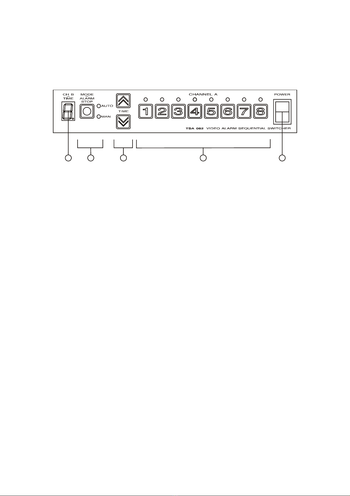
ALARM SPECIFICATION
When only one alarm input is activated, the
alarmed video input appears on the CHANNEL
A or CHANNEL B. Buzzer is activated. On the
CHANNEL A auto and manual LEDs blink.
When the CHANNEL B is selected the decimal
point on the LED display blinks. Alarm output is
activated (switched to the ground). When more
then one alarm input is activated, the alarmed
video inputs appear on the CHANNEL A or
CHANNEL B sequentially.
The CHANNEL B is automatically switched from
sequential mode to frame-by-frame mode when
the ALARM FRAME SWITCHING is enabled.
This function is disabled when the VCR CLOCK
is selected.
Alarm sequential time and alarm duration time
are adjusted in the SET-UP. With pressing the
key ALARM STOP manual reset of the alarm is
achieved on the CHANNEL A.
REMOTE CONTROL
Remote control possibility on the CHANNEL A
appears when the auto (sequential) mode is
selected. Key T1 is used to stop and start the
auto sequence. When it is stopped key T2 is
used for manual scan. In the set-up, REMOTE
CONTROL has to be selected.