ASTON HARALD M32 CATAMARAN User manual

1
M32 CATAMARAN
ASSEMBLY MANUAL

2
M32 CATAMARAN
ASSEMBLY MANUAL
TECHNICAL INFORMATION
UNLOAD TRAILER
PLATFORM ASSEMBLY
MAST ASSEMBLY
MAST STEPPING
BOWSPRIT ASSEMBLY
RUDDER ASSEMBLY
RACK ASSEMBLY
SAILING PREPARATIONS
RIG SETTINGS
MAIN HALYARD LOCK
This manual is a guide for assembling the boat and stepping the mast and AHC takes no responsibility
for damages caused while assembling the boat. If a problem or irregularity arises while assembling the
boat, contact your local M32 representative.
4
6
12
20
30
46
52
56
60
64
72
GET ASSEMBLY VIDEO
INSTRUCTIONS AT: M32WORLD.COM

3

4
The instructions in this manual are made with the intention of making
owners safely put together, handle and use the boat for training and racing.
The M32 is a high performance racing boat designed and dimensioned for
inshore racing and should be used accordingly.
WE WANT TO STRESS THE IMPORTANCE OF FOLLOWING THIS MANUAL WHEN ASSEMBLING,
HANDLING AND SAILING THE M32. HAVING THE RIG ACCORDING TO THE RECOMMENDED
SETTINGS WITH THE SPREADER ANGLE, DIAMOND TENSION AND MAST RAKE BEING THE KEY
PARAMETERS.
RIG
•Mast rake should be 480mm +/- 5
mm.
•The diamond tension using the Loos
& Co. gauge RT-10M (3,2-7,1mm) with
the base of the gauge in just above
the mast winch is recommended to be
in the interval 45-55.
•Spreader angle should be 190mm +/-
5mm.
•The soft rig setting is constantly
changing due to material properties.
It is important to always check the rig
settings before any sailing.
•We recommend Spinlock Rig Sense
RGS/0508 for measuring the aft stay
tension.
•Ensure that the cunningham line is
not resting on the diamond stay, a
dyneema can be put around the goo-
seneck to get a better angle for the
ring/block.
•The gennaker luff length should be
15,630 meter, measured bearing to
bearing, with a tension of 40 Kg on
the luff.
•In rig setting point 2 the measuring
point is defined as 70 mm above the
joint on the backside of the aft beam.
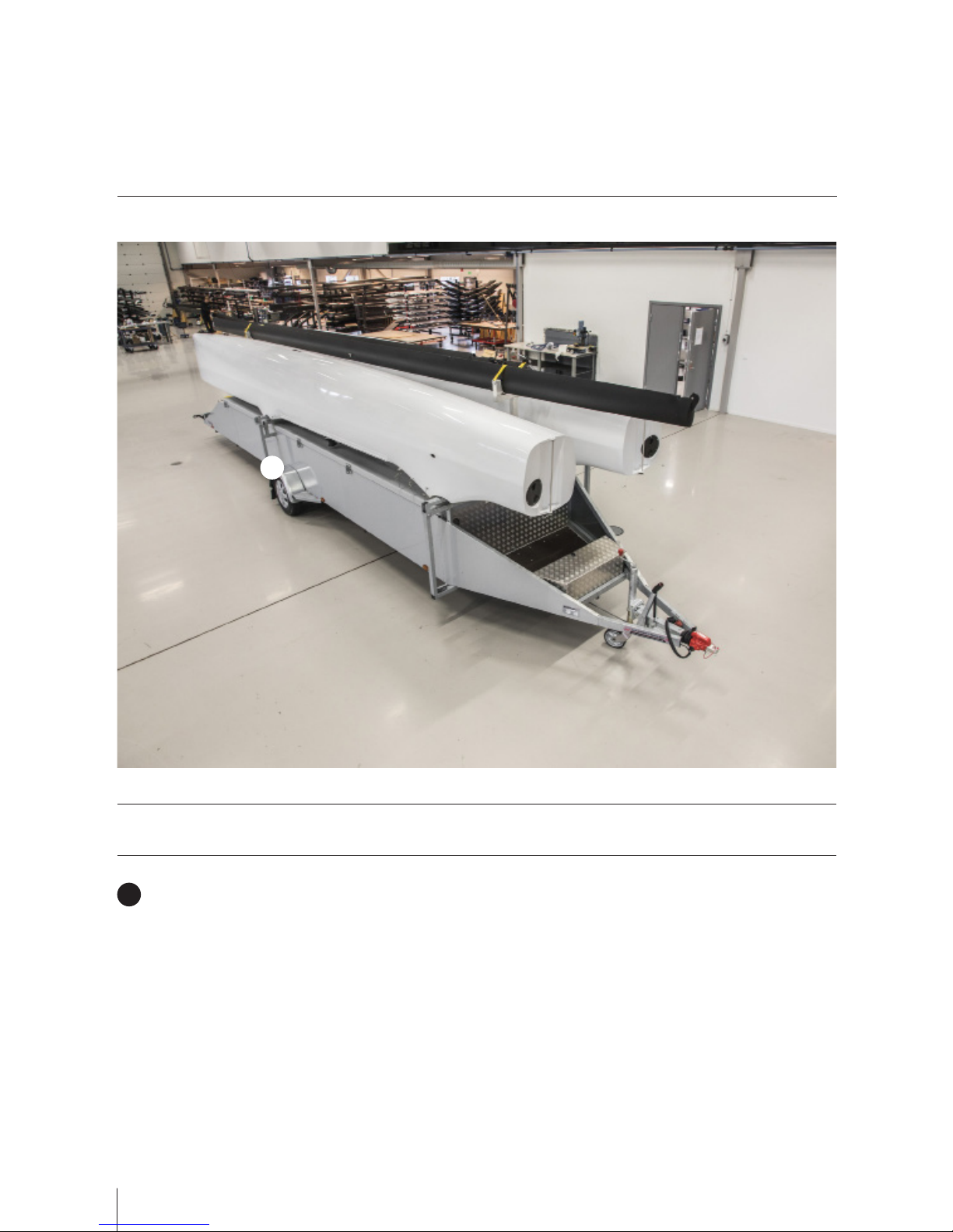
M32 CATAMARAN
TECHNICAL INFORMATION

5
PLATFORM AND APPENDAGES
TECHNICAL INFORMATION
BOAT HANDLING
HALYARD LOCK
•It is recommended to grease all bolt
treads. The bolts should be cleaned
and the threads protected at every
disassemble of the M32 to extend the
lifetime of the bolts and to avoid the
risk of the bolts to get stuck when
assembling. We recommend Molykote
1000 or similar.
•We recommend to use Norbar Model
1523 Torque wrench (10 - 50 Nm) or
similar for tensioning the beam bolts,
traveler bolts and strut bolts.
•The gennaker should only be hoisted
when the mainsail is fully up or at the
first reef, having the gennaker luff
tightened when the mainsail is at the
second reef is not allowed. To have
the gennaker up when sailing with two
reefs will risk losing the mast as the
mainsail is supporting the mast.
•The mainsheet and traveler combined
is supporting the mast both upwind
and downwind and the gennaker
needs to be eased prior to the main-
sheet when depowering the sails.
•Make sure that the steel locking arm
on the halyard lock is all the way
down into the groove when locked.
Do not connect the cunningham or
boom if this is not the case as it is not
designed to take the load unless the
steel locking arm is all the way into
the groove.

6
UNLOAD TRAILER
PARTS AND TOOLS
1
PARTS INCLUDED
Trailer
1

7
1
2
TOOLS INCLUDED
Ratchet spanner
1
19mm socket
2

8
UNLOAD TRAILER
INSTRUCTIONS
Make sure the handbrake his on.
Unlock the handles so that the hulls can be folded down.
1
2

9
Take the starboard hull down.
Put on the trolleys. They are labeled forward, FWD, and aft, AFT.
3
4
TIP! Make sure bolts are in good condition and store the spanner and bolts in the storage box
in the front of the trailer.

10
Use a 19 mm spanner to get the hull off the trailer arms.
5
Take the port hull down.
Put on the trolleys. They are labeled forward, FWD, and aft, AFT.
6
7

11
Use a 19 mm spanner to get the hull off the trailer arms.
Take off the cross beam to be able to open the hatch.
8
9
TIP! You do not need to take othe mast to be able to open the hatch.

12
PLATFORM ASSEMBLY
PARTS AND TOOLS
1
4
2
3
7
PARTS INCLUDED
Main beam
1
4x Traveler bolts (Incl. washer)
3
Furlingline
5
Override preventers
6
Trampoline
7
Aft beam
2
8x Beam bolts
4
5
6

13
1
2 3
4
5
6
TOOLS INCLUDED
Brush
1
Grease
2
16mm socket
3
Ratchet spanner
5
19mm socket
4
Torque wrench
6

14
Position the two hulls, with the trampoline tracks and winches
facing inwards, so that the beam beds line up.
Place the main and aft beam in the beam beds.
1
2
PLATFORM ASSEMBLY
INSTRUCTIONS
TIP! Make sure to clean the surfaces from grease rests and/or dirt. For any bumps or irregu-
larities that are not coming o, use a 240 grid sandpaper. The surface needs to be even for
the best tting othe beams.

15
Grease and fasten the beam bolts using a 19 mm spanner. The
bolts should be tightened to 40 Nm using a torque wrench.
Fasten the 4 traveler track bolts with washers from inside the
cockpits. The bolts needs to be greased before they are inserted
and tighten. The bolts should be tightened to 20 Nm with a torque
wrench.
3
4
TIP! It can sometimes be a bit tricky to get all the holes to line up. To facilitate the assembly;
start to line up one of the inner holes and tighten the beam bolt, leave it with a bit of play.
Then continue with the other inner ones going around and then do the same procedure with
the outer ones. When all bolts are in, tighten to 40 Nm. Recommended is also to go over the
bolts with the torque wrench when the boat is in the water to make sure all bolts are properly
tightened.

16
Position the trampoline behind the boat with the side with two
glass fibre rods facing forward and with the forward and aft seams
are pointing against the main beam and aft beam respectively.
5
Slide all the trampoline sliders into the tracks on both sides. To be
able to get the front and back lashing into position, untie the sliders
on the sides so that there is no tension on the trampoline.
6
TIP! Easiest way is to be two persons, one from each hull. Be careful so that the glass bre
rods are not scratching the hulls.

17
For the aft beam lashing, start with making a loop in the middle of
the lashing and then lash outwards from the middle.
Attach the lashing in the eyebolts in the corners of the trampoline
and tighten. This will help to get the rods straight and avoid any large
gaps between hull and trampoline.
Fasten the trampoline by running the lashing as shown on the
picture. Start with the lashing on the main beam and start from the
middle and work out towards the hulls to get the tension of the net
straight and to stretch the net as much as possible for good tension.
8
9
7
TIP! Remember that the lashing and the net is a living material meaning that it will stretch
and behave dierently given the govern environment.

18
Tension the sliders on both sides. To prevent the rods from bre-
aking, do not tight too hard the first round and tension every other
slider. Then go over a second turn and tension the ones not tighte-
ned. Then all sliders can be tensioned equally hard.
Place the furling line around the mast knob and make sure it is
not twisted.
10
11
Tensioning will have to be done prior each time of
sailing since the lashing and net is stretching.
IMPORTANT!

19
Mount/check override protectors. Remember that with a loose
tensioned trampoline the angle of the gennaker sheet going onto the
winch will vary.
12

20
MAST ASSEMBLY
PARTS AND TOOLS
1
7
8
42
3
6
5
10
11
9
PARTS INCLUDED
Spreaders
1
Loop halyard small
3Diamond stay upper
7
Cunningham
5
Diamond stay lower
8
Lower mast
9
Upper mast
10
Halyard lock (mast car)
11
Main halyard
2
Gennaker halyard
4
The diamond stays should be handled with care
and kept secured in the bowsprit during transport.
IMPORTANT!
Rotation Line
6
Other manuals for M32 CATAMARAN
1
Table of contents
Other ASTON HARALD Boat manuals