10
Tension the diamond turnbuckle until you
get your required prebend.
Prebend should be a minimum of 70mm
with full main and 80mm when sailing with
a reef.
Prebend is defined in this case as the
distance between the trailing edge at the
spreader and an artificial straight line
between the upper most point and lowest
point of the trailing edge of the luff track.
When measuring the prebend the mast
supports shall be placed 150cm above the
bottom end of the mast and one 20cm
above the upper diamond stay fitting.
8
9
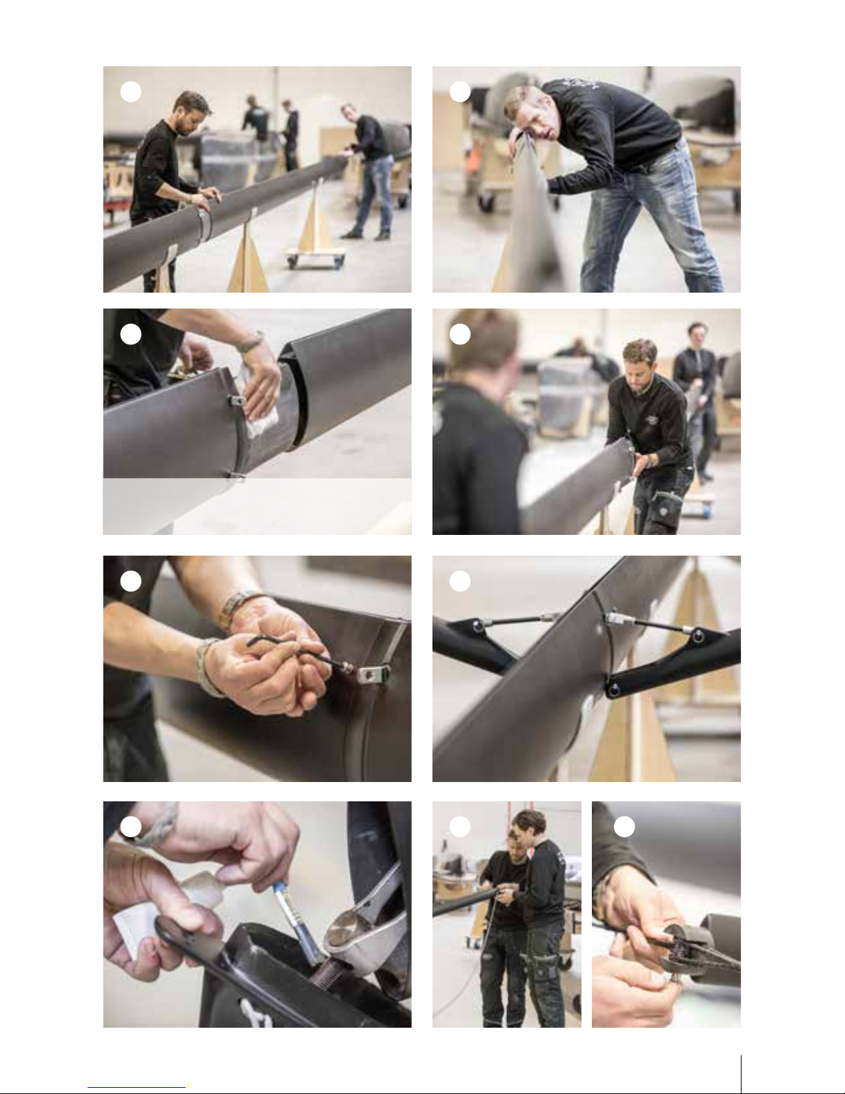
It is VERY IMPORTANT that the clevis pin is orientated with the head facing towards the trailing
edge of the mast and the key ring is towards the leading edge of the mast. The shrouds can be
damaged and the mast can fall down if the clevis pin is orientated the wrong way.
The halyards need to have a diameter
of 8mm to prevent the halyards to
come out through the luff track. Do
not remove the cover or use lesser
diameters.
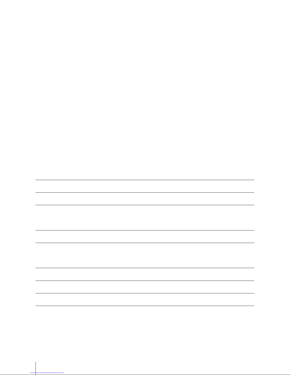
VERY IMPORTANT!
IMPORTANT!
Remove the top sheave to insert the Main
halyard. Use a small hook to pull the haly-
ards through the luff track. Tie the sail head
end of the halyards to the mast close to the
mast foot.
Let the Gennaker halyard at the bottom go
through the spinlock on port side of the
mast.
The diamond tension using the Loos & Co.
gauge RT-10M(3,2-7,1mm) with the base of
the gauge in just above the mast winch is
recommended to be in the interval 45-55.
If the required prebend is not reached at 55
on the gauge the spreader angle needs to
be adjusted.
Let the Main halyard at the bottom go
through the block on starboard side and up
to the winch.
10
12
13
11
How to check the spreader angle:
Pull a string tight between the center of the
spreader tips and measure the distance
between the string and the trailing edge of
the mast at the joint. Standard measure-
ment is 190mm, minimum is 180mm and
maximum is 200mm. Larger spreader angle
will give more mast prebend. The adjusted
length of the spreader turnbuckles must be
the same on both sides. A halft turn on turn-
buckles gives approximately a 5mm change
in spreader angle. As shown in picture 7a the
string should be pulled just above the end
fitting on top of the diamond stay.
7