6 Manual de instalación, operación y mantenimiento; Level Control System
-No manipular el equipo con las manos húmedas o mojadas.
-El acceso al equipo es únicamente posible para personal autorizado o para técnicos
facultados. No permitir el acceso a personas no autorizadas o técnicamente no
preparadas.
2INSTALACIÓN Y MONTAJE
AVISOS:
-Leer atentamente todo el manual antes de proceder a la instalación del equipo.
-Al recibir el equipo, comprobar que se encuentra en buen estado.
-Identificar todos los componentes previos a su instalación.
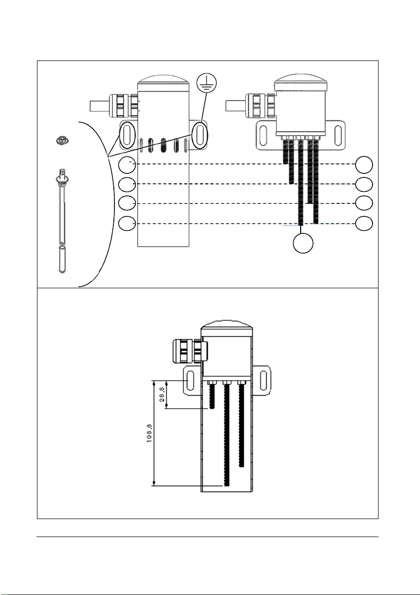
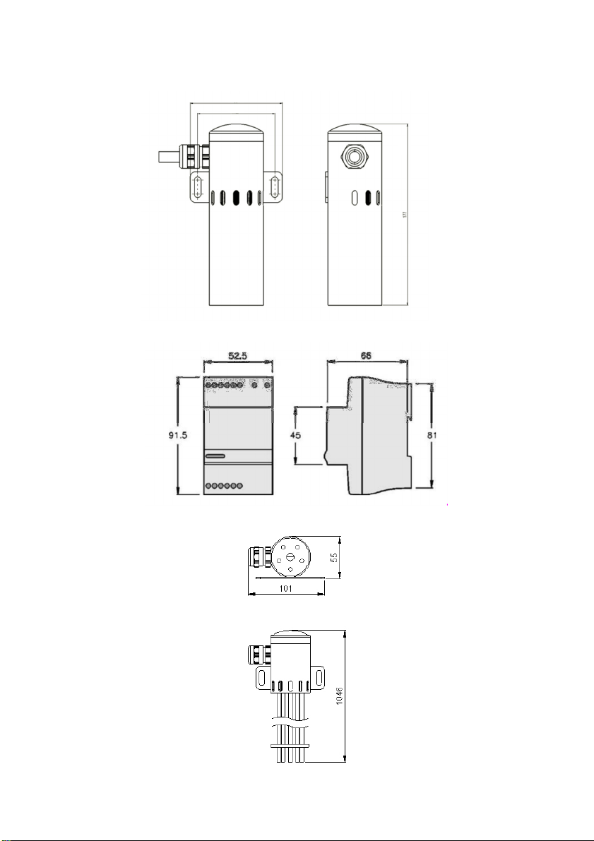
2.1 FIJACIÓN Y NIVELACIÓN DEL SENSOR
Componentes requeridos para la fijación del equipo:
Fijación en función de la instalación del usuario 2
Arandela plan DIN 9021 D6 A4 4
Tuerca DIN 934 M6 A4 4
1) Fijar los anclajes (②
②②
②
c) a la pared de la fuente.
AVISO: Riesgo de daño al equipo. Nivelar el equipo de forma que el nivel de agua máximo
de la fuente no supere la altura de la posición n4 y el nivel minímo no sea inferior a la varilla
n1 (ver Fig. 1). La función de las ranuras ubicadas sobre la posición n4 es permitir la
entrada y salida de aire al o del interior del sensor y evitar la creación de bolsas de aire.
AVISO: Riesgo de daño al equipo. Proteja eléctricamente el equipo conectando una toma
tierra (
③
③③
③
) a una de las dos uniones anclaje-tuerca (②
②②
②).
2) Fijar y nivelar el equipo en cada punto de fijación del equipo (②
②②
②) con
•un conjunto de una tuerca y arandela (②
②②
②
a) en la parte frontal y
•un conjunto de una tuerca y arandela en la parte posterior (②
②②
②
b).
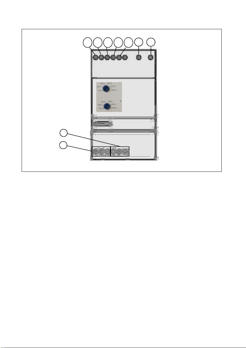
2.2 FIJACIÓN DE LA UNIDAD DE CONTROL
AVISO: Riesgo de daño al equipo. Fijar la unidad de control fuera de la fuente. El nivel de
protección de la unidad de control es IP-20.
La unidad de control cuenta con un carril DIN para su montaje en un cuadro eléctrico.