EMP OK1 Manual

Rev
Rev By
Date
Description of Change
Approved By
G
ME
5/19/22
Revisions
ECN7628
H
ME
1/10/23
Revisions
ECN8814
9980029073 Rev. H – 01/10/2023 © 2011 EMP, Inc. 1
Installation and Service Manual
OK1/OK2 Oil Cooler Assembly
This manual is effective for the installation and service of OK1 and OK2 systems
with 11” fans. See System Part Numbers for a complete list of systems.

Product Overview
© 2011 EMP, Inc. 2
Engineered Machined Products Inc.
2701 North 30th Street
Escanaba, MI, USA 49829
Phone: +1 (906) 789-7497
www.emp-corp.com
service@emp-corp.com
Product Overview
The EMP OK1/OK2 oil cooling systems are advanced thermal management products designed for applications
requiring cooling of hydraulic oil, system oil, transmission oil, fluid or any other general cooling application using
oil or a similar fluid. Benefits include lower energy consumption, reduced noise, individual fan diagnostics and
improved temperature control. This document defines the installation requirements and service parts
replacement requirements for the OK1 and OK2 system part numbers listed in System Part Numbers.
The installation requirements defined in this document must be followed in order to ensure the proper operation
and service life of OK1 and OK2 thermal systems.

Table of Contents
© 2011 EMP, Inc. 3
Table of Contents
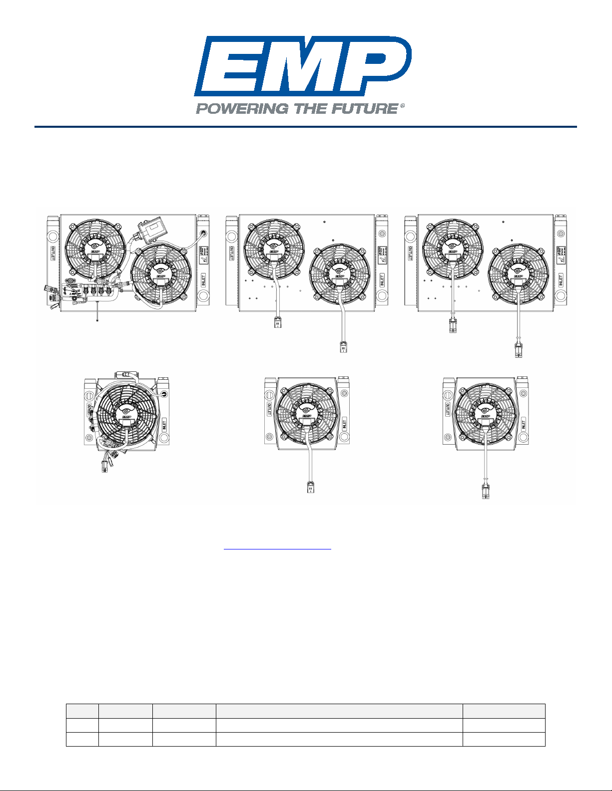
Product Overview ..............................................................................................................................................2
Introduction........................................................................................................................................................4
Purpose .........................................................................................................................................................4
Service Technician Responsibilities ...............................................................................................................4
Liability Disclaimer .........................................................................................................................................4
More Information............................................................................................................................................4
Routine Maintenance .....................................................................................................................................4
Technical Help ...............................................................................................................................................4
Warranty ........................................................................................................................................................4
About This Document ........................................................................................................................................5
Warnings, Cautions and Notes.......................................................................................................................5
Definition of Terms.........................................................................................................................................5
Product Safety Warnings ...................................................................................................................................6
System Configurations.......................................................................................................................................7
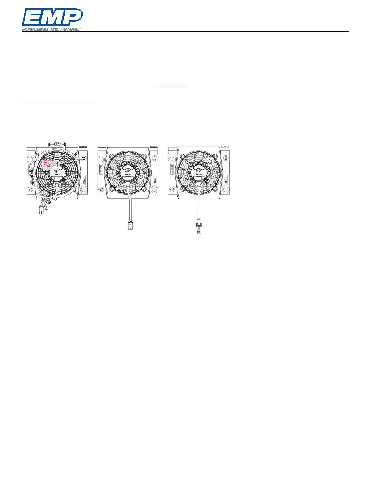
Product Identification......................................................................................................................................7
Model Codes..................................................................................................................................................7
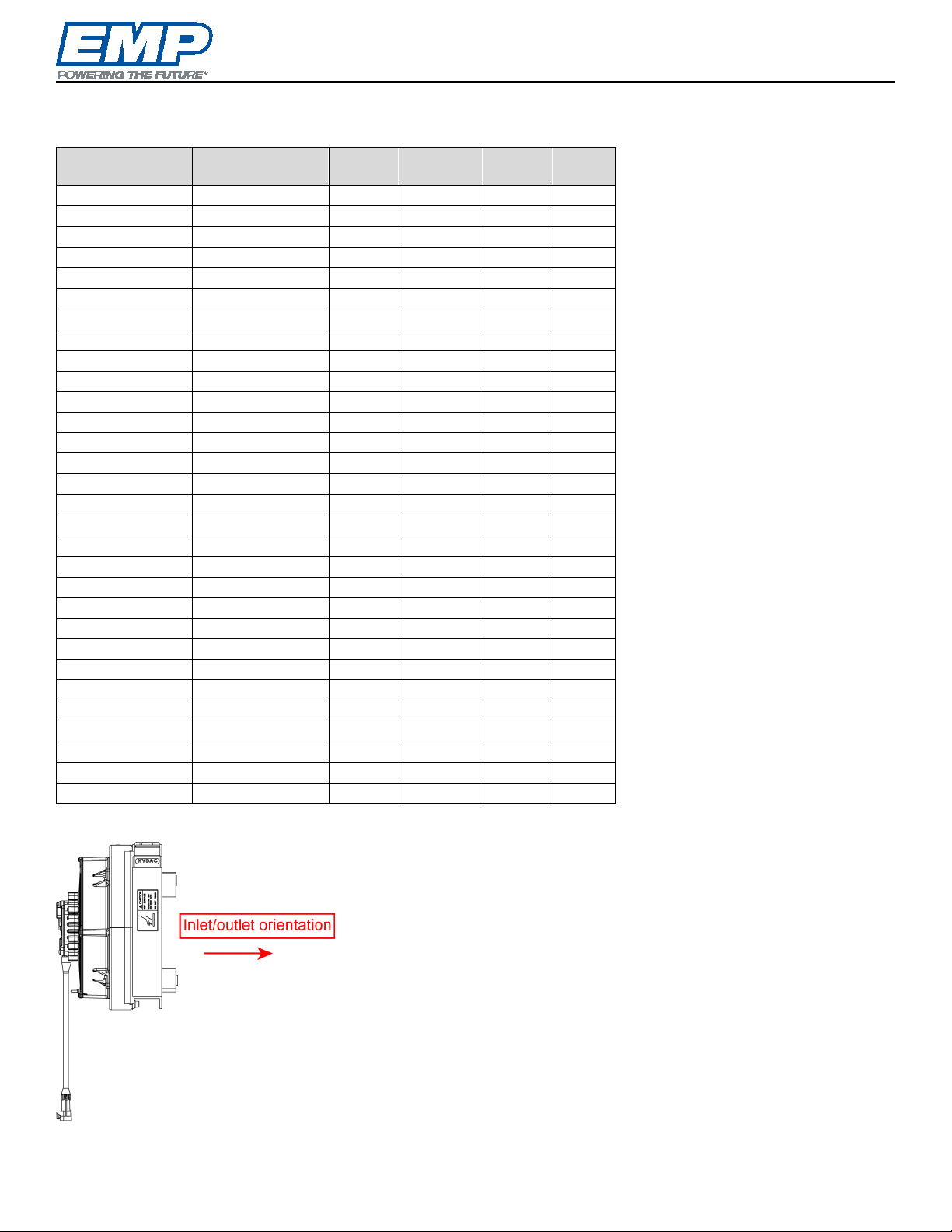
Airflow Direction .............................................................................................................................................7
System Part Numbers ....................................................................................................................................8
System Information............................................................................................................................................9
Operation .......................................................................................................................................................9
OK1 ...............................................................................................................................................................9
OK2 .............................................................................................................................................................10
Common Specifications and Operating Limits .............................................................................................. 11
Wiring and Fusing Requirements .................................................................................................................11
Heat Rejection .............................................................................................................................................12
μTMC Controlled Systems ...........................................................................................................................13
Installation .......................................................................................................................................................17
Orientation ...................................................................................................................................................17
Mounting ......................................................................................................................................................18
Plumbing......................................................................................................................................................20
Wiring and Fusing Recommendations..........................................................................................................21
Software Calibration Options........................................................................................................................22
Troubleshooting...............................................................................................................................................22
Service Parts Replacement .............................................................................................................................23
Connector Greasing .....................................................................................................................................23
Fuse Replacement .......................................................................................................................................23
FIL11 Fan ....................................................................................................................................................24
μTMC System Controller.............................................................................................................................. 25
Power/Ground Stud Replacement Kit (1370090014) – (If Required) ............................................................ 26
Main Wire Harness.......................................................................................................................................27
OK1 Harness Installation..............................................................................................................................28
OK2 Harness Installation..............................................................................................................................29
Heat Exchanger Replacement for OK1/OK2 ................................................................................................ 30
Shroud Replacement for OK1/OK2 ..............................................................................................................31
Fluid Thermistor ...........................................................................................................................................32
Service Tool Interface ..................................................................................................................................32
Appendix A – Wiring Schematics.....................................................................................................................33
3170029067.................................................................................................................................................34
3170029068.................................................................................................................................................35
3170029068, Rev D and Later ..................................................................................................................... 36
Appendix B – Operation Manual μTMC System Controller .............................................................................. 37
Product Warranty Registration Form................................................................................................................ 38

Introduction
© 2011 EMP, Inc. 4
Introduction
Purpose
The purpose of this document is to define the installation and service requirements of the OK1 and OK2 system
part numbers that are listed in System Configurations. The requirements defined in this document must be
followed in order to ensure proper operation and service life of OK1 and OK2 thermal systems.
Service Technician Responsibilities
Ensure that all safety messages and information messages are read and understood before installation,
maintenance, or repairs are performed. It is important to use caution when service work is performed. Knowledge
of impacted systems and their operation are important before the removal or disassembly of any component.
Knowledge of hazards present and risk of injury to the service technician while working on these systems is
critical to personal safety.
Liability Disclaimer
EMP cannot anticipate every possible circumstance that might involve a potential hazard. The safety messages
in this document, in related manuals, and on the product are therefore not all inclusive. If a tool, procedure, work
method, or operating technique that is not specifically recommended by EMP is used, you must satisfy yourself
that it is safe for you and for others. You should ensure that the product will not be damaged or be made unsafe
by the operation, maintenance, or repair procedures that you choose.
More Information
Documents and software referenced in this manual are available for download from the support section of the
EMP website, https://www.emp-corp.com/support/.
Routine Maintenance
Routine maintenance schedule and procedures are outlined in service bulletin 9910039031.
Technical Help
Contact EMP Technical Service for technical help at +1 (906) 789-7497 or service@emp-corp.com.
Warranty
Mail, Fax, or Email the completed warranty registration form at the end of the document to:
EMP Advanced Development, LLC
2701 North 30th Street
Escanaba, MI, USA 49829
Fax: +1 (906) 789-7825
warranty@emp-corp.com

About This Document
© 2011 EMP, Inc. 5
About This Document
Warnings, Cautions and Notes
Two headings are used in this document to stress your safety and safe operation of the system. They are styled
with a graphic bullet and bold, uppercase text: WARNING and CAUTION. Warnings highlight risks to
personnel — hazards, unsafe conditions and practices that can result in personal injury or death. Cautions
indicate conditions or practices that can cause damage to components, systems, or other equipment.
A third heading, styled as NOTE, calls attention to additional information about components and procedures
discussed in the document.
Definition of Terms
CAN .............. Controller area network.
LED ............... Light-emitting diode.
EMP-Link...... EMP proprietary component to component communication network.
µTMC ............ EMP micro thermal management system controller.
!
!

Product Safety Warnings
© 2011 EMP, Inc. 6
Product Safety Warnings
WARNING: EMP cannot anticipate every possible circumstance that might involve a potential hazard.
The safety messages in this document, in related manuals, and on the product are therefore not all inclusive.
If a tool, procedure, work method, or operating technique that is not specifically recommended by EMP is
used, you must satisfy yourself that it is safe for you and for others. You should ensure that the product will
not be damaged or be made unsafe by the operation, maintenance, or repair procedures that you choose.
WARNING: Ensure that all safety messages and information messages are read and understood before
installation, maintenance, or repairs are performed. It is important to use caution when service work is
performed. Knowledge of impacted systems and their operation are important before the removal or
disassembly of any component. Knowledge of hazards present and risk of injury to the service technician
while working on these systems is critical to personal safety
WARNING: Ensure that the equipment cannot move before doing any work or diagnostic procedures
on the EMP component, system, or vehicle.
WARNING: When working on or near electrical components, ensure that they have been disconnected
from their energy source, cannot be accidentally re-energized, and verify the system is in a zero energy
state.
WARNING: Use extreme caution when working on systems under pressure (i.e. coolant, hydraulic
fluids, air, fire suppression, etc.).
WARNING: Ensure the work area is ventilated and well lit.
WARNING: Ensure charged fire extinguishers are in the work area.
WARNING: Ensure all safety guards, shields, and covers are reinstalled when tasks are completed.
WARNING: Ensure all tools, parts and service equipment are removed from the work area.
WARNING: Ensure that all system power and ground connection points are torqued to EMP and/or
OEM specifications to prevent system damage. Failure to follow specified torque requirements can result in
loose connections which can damage electronic components and will void EMP warranty.
!
!
!
!
!
!
!
!
!
!

System Configurations
© 2011 EMP, Inc. 7
System Configurations
Product Identification
The system product label, located on the upper left of the fan side on both OK1 and OK2 systems, lists the model
code, system part number, and serial number of the system. The serial number can be used to obtain system
configuration and all information necessary for component replacements.
Each fan has a product label giving the model code, part number, and serial number of the fan. Fans should be
replaced with a matching part number. The serial number can be used to obtain information about the hardware
and software configuration of the fan.
Model Codes
The OK1 and OK2 oil coolers discussed in this manual share 12 model codes indicating the number of fans,
main dimensions, voltage, and certifications of each system.
Model Code
Fans
Dimensions (in)
Voltage (V)
Certification
OK1-1714-12V
1
17x14
12
-
OK1-1714-24V
1
17x14
24
-
OK1-1714-12V C
1
17x14
12
CSA
OK1-1714-24V C
1
17x14
24
CSA
OK1-1714-12V U
1
17x14
12
UL
OK1-1714-24V U
1
17x14
24
UL
OK2-3219-12V
2
32x19
12
-
OK2-3219-24V
2
32x19
24
-
OK2-3219-12V C
2
32x19
12
CSA
OK2-3219-24V C
2
32x19
24
CSA
OK2-3219-12V U
2
32x19
12
UL
OK2-3219-24V U
2
32x19
24
UL
Airflow Direction
Systems are available with pusher or puller fans, and with different control strategies. The system part number
tables in this section give the fan direction (in the description) and control strategy for each part number.

System Configurations
© 2011 EMP, Inc. 8
System Part Numbers
OK1 and OK2 system configurations vary in voltage, control strategy, fan.
12 Volt Part
Number
24 volt Part
Number
Type Control Cert Fan
2020029049
2020029050
OK1
μTMC
-
Pull
2020029051
2020029052
OK1
μTMC
-
Push
2020029150*
-
OK1
μTMC
-
Push
2020029053
2020029054
OK1
R20L
-
Pull
2020029055
2020029056
OK1
R20L
-
Push
2020029148*
-
OK1
R20L
-
Push
2020029076
2020029077
OK1
R20L
CSA
Push
2020029078
2020029079
OK1
R20L
CSA
Pull
2020029080
2020029081
OK1
R20L
UL
Push
2020029082
2020029083
OK1
R20L
UL
Pull
2020029084
2020029085
OK1
μTMC
CSA
Push
2020029086
2020029087
OK1
μTMC
CSA
Pull
2020029088
2020029089
OK1
μTMC
UL
Push
2020029090
2020029091
OK1
μTMC
UL
Pull
2020029125
2020029126
OK1
R20C
-
Push
2020029127
2020029128
OK1
R20C
-
Pull
2020029058
2020029059
OK2
μTMC
-
Pull
2020029060
2020029061
OK2
μTMC
-
Push
2020029062
2020029063
OK2
R20L
-
Pull
2020029064
2020029065
OK2
R20L
-
Push
2020029093
2020029094
OK2
μTMC
CSA
Pull
2020029095
2020029096
OK2
μTMC
CSA
Push
2020029097
2020029098
OK2
μTMC
UL
Pull
2020029099
2020029100
OK2
μTMC
UL
Push
2020029101
2020029102
OK2
R20L
CSA
Pull
2020029103
2020029104
OK2
R20L
CSA
Push
2020029105
2020029106
OK2
R20L
UL
Pull
2020029107
2020029108
OK2
R20L
UL
Push
2020029121
2020029122
OK2
R20C
-
Pull
2020029123
2020029124
OK2
R20C
-
Push
* 2020029148 and 2020029150 have the fluid inlet and outlet oriented opposite the fan.

System Information
© 2011 EMP, Inc. 9
System Information
Operation
Systems with a μTMC provide temperature-based fan speed control. A harness connects the μTMC and fans
and provides power, ground, a connector for an optional on-board diagnostic lamp/pushbutton and a connector
for interfacing with service tools. Reference Appendix B, Operation Manual μTMC System Controller for more
information. For assistance with system calibrations or settings please contact EMP Technical Service at
service@emp-corp.com and provide a serial number for the part in question.
For information about interfacing with and operating the fans on systems with R20L and R20C control strategy,
refer to Service and Installation Manual 11 Inch Axial Fan Assembly, EMP document 9980036021.
OK1
Maximum current consumption 25 amps
Ignition enable switched 9–32 volt source
Overall package length 16.5 inches
Overall package width 14 inches
Overall package depth 9 inches
Weight (without fluid) 33 pounds
SAE O-ring port size -16
Inlet and outlet thread size 1 5/16-12 UN
Maximum pressure drop in cooler 8 psi
@ 30 mm2/sec and 30 gpm
Heat exchanger volume 0.6 gallons
μTMC Controlled Systems
Harness assembly 3170029067
Fan 1 address resistance Open

System Information
© 2011 EMP, Inc. 10
OK2
Maximum current consumption 50 amps
Ignition enable switched 9–32 volt source
Overall package length 32 inches
Overall package width 19 inches
Overall package depth 10 inches
Weight (without fluid) 75 pounds
SAE O-ring port size -20
Inlet and outlet thread size 1 5/8-12 UN
Maximum pressure drop in cooler 12 psi
@ 30 mm2/sec and 30 gpm
Heat Exchanger Volume 0.8 gallons
μTMC Controlled Systems
Harness assembly 3170029068
Fan 1 address resistance: Open
Fan 2 address resistance: Short

System Information
© 2011 EMP, Inc. 11
Common Specifications and Operating Limits
Fluids Range from Mineral Oil to DIN 51524 Part 1 and Part 2.
Heat exchanger material Aluminum
Shroud material Steel
Maximum ambient operating temp 95 °C
Minimum operating temp -40 °C
Maximum storage temp 125 °C
Minimum storage temp -50 °C
Maximum oil temp 130 °C
Minimum operating speed 750 rpm
Maximum operating speed (12V) 4000 rpm
Maximum operating speed (24V)* 4600 rpm
Maximum continuous operating pressure 230 psig
Internal bypass pressure value 45 psig
Maximum recommended oil flow rate** 45 gpm
Heat exchanger fin/inch 12 fins/inch
Maximum viscosity 2000 cSt
NOTE: Higher fan speeds are available but conditions must be approved by EMP.
NOTE: Higher flow rates can be used but fluid conditions must be reviewed.
Wiring and Fusing Requirements
Maximum continuous operating ambient temp 95 °C
Wire jacket temp rating 125 °C
Wire sleeve and loom temp rating 125 °C
Nominal fuse rating/fan 30 amps
Wire jacket material XLPE

System Information
© 2011 EMP, Inc. 12
Heat Rejection
Inlet Temperature Differential (ITD) = (oil temperature into cooler - air temperature into cooler)
The performance of the system can vary ±10%.
No external system restriction or airflow recirculation represented in test data. The system must be validated in
the application to determine the affect additional system restriction and airflow recirculation have on
performance.
4000 rpm is the maximum speed setting on 12V OK1 and OK2. The 4000 rpm line represents the maximum
performance achievable at 12V.
4600 rpm is the maximum speed setting on 24V OK1 and OK2. The 4600 rpm line represents the maximum
performance achievable at 24V.
Depending on ambient conditions and duty cycles, cooler performance exceeding the 4600 rpm line can be
achieved with 24V systems. Contact EMP to discuss these special cases.
The test results are for fans in puller configuration. Contact EMP for pusher configuration data.

System Information
© 2011 EMP, Inc. 13
μTMC Controlled Systems
On μTMC systems, a harness is used to distribute vehicle power from the power and ground studs, for
component fusing, for component communication and for temperature input. The harness also has connections
for ignition enable, an onboard diagnostic lamp/pushbutton, and for communication with software service tools.
Open and short addressing within the harness assembly is used to set the EMP-Link addresses for the individual
FIL11 fans. The harness is secured to the OK1/OK2 shroud using cable ties and/or J clips.
Operation initiates when the μTMC controller and fans receive the ignition enable signal. The μTMC monitors
temperatures and adjusts fan speeds to provide the required cooling. If communication is disrupted, the fans will
continue to run at a programmed default speed.
A single fan part number is used for both locations on OK2 systems. The EMP-Link addresses used by the fans
are set by reading resistance values from the harness.
System Schematic
NOTE: OK2 schematic shown. For OK1 remove wiring to second fan and eliminate second 30A fuse.
Temperature Controlled OK1/OK2 Schematic
CAUTION: Ensure that all system power and ground connection points are torqued to EMP
specifications to prevent system damage. Failure to follow specified torque requirements at any point of the
vehicle system power and ground can result in loose connections which can damage electronic components
on the system and will void EMP warranty.
!

System Information
© 2011 EMP, Inc. 14
OK1 harness 3170029067
OK1 Harness Connections
NOTE: The harness is routed and secured to the system to prevent water damage, premature wear, and
other system damage. When replacing the harness, take care to properly route and secure the system
harness.
OK1 Harness Layout

System Information
© 2011 EMP, Inc. 15
OK2 Harness 3170029068
NOTE: Harnesses shipped after June 2021 remove a wire from Fan 1 and the EMP-Link connector. The
removed wire does not impact the function of the system.
OK2 Harness Connections
NOTE: The harness is routed and secured to the system to prevent water damage, premature wear, and
other system damage. When replacing the harness, take care to properly route and secure the system
harness.
OK2 Harness Layout

System Information
© 2011 EMP, Inc. 16
Manual Fan Reverse Input
A fan reverse input is available on μTMC systems. The input is designed for use with a momentary switch.
Momentarily closing and opening the fan reverse input will trigger the calibrated fan reverse cycle.
Diagnostic Lamp Output
A diagnostic lamp can be connected to the system through a 4-pin connector. This diagnostic lamp will flash out
blink codes to the technician to indicate the source of the fault when the vehicle is running. The format for the
blink fault codes is XX-YY where:
XX is the first number of the fault code
YY is the second number of the fault code
The blink codes are read out in the following manner:
1. Warning lamp on for 4 seconds to mark the start of the fault code list
2. Off for 2.5 seconds to indicate the start of a fault code
3. A sequence of 0.5 second blinks the number of which indicates the first number (XX) of the fault code.
4. Off for 1.25 seconds to indicate the start of the second digit of the fault code.
5. A sequence of 0.5 second blinks the number of which indicates the second number (YY) of the fault code.
6. If multiple fault codes are active, the next fault code will be communicated beginning with step 2. When all
fault codes have been communicated, the fault code list will be repeated beginning with the long on time
of step 1.
7. The sequence will be repeated until the fault condition is removed or cleared manually
8. A table listing the meaning of the blink codes can be found in the Help menu of the Service Tool.
Power and Ground Stud Assembly
WARNING: To avoid serious personal injury, possible death, or damage to the vehicle, disconnect the
main negative battery terminal and/or switch off the battery disconnect switch first before removing or
installing any electrical components.
CAUTION: Ensure that all system power and ground connection points are torqued to EMP
specifications to prevent system damage. Failure to follow specified torque requirements at any point of the
vehicle system power and ground can result in loose connections which can damage electronic components
on the cooling system and will void EMP warranty.
!
!

Installation
© 2011 EMP, Inc. 17
Installation
Orientation
OK1 and OK2 systems must be installed in an orientation that minimizes trapped air. It is preferred that the
installation orientation prevent pooling of liquid on sealed surfaces.
Preferred Orientations
All connectors are properly oriented to prevent pooling of fluid on sealing surfaces. Tanks oriented to minimize
chances of air entrapment.
Not Preferred Orientations
Some connectors are not properly oriented to prevent pooling of fluid on sealing surfaces.

Installation
© 2011 EMP, Inc. 18
Unacceptable Orientations
The tanks are not oriented to minimize chances of air becoming trapped and most connectors are not oriented
properly to prevent pooling of fluid on sealing surfaces.
Mounting
The oil cooler may be rigid mounted if vibration levels are not excessive. For excessive vibration, the cooler must
be isolation mounted. Due to variance in mounting brackets, fasteners and vibration levels, the cooler should be
validated in each unique application by the end user to ensure it meets the end user’s requirements. Contact
EMP for assistance and approval.
Airflow obstructions should be kept at least 2 inches from the inlet and outlet of the fan/heat exchanger assembly
for optimal performance.
Refer to the orientation recommendations made above. They are intended to minimize the chance of trapping
air in the system and to provide the best possible wire management for component sealing.
For optimum performance ensure the cooler draws in the lowest temperature air available. Seal the air inlet side
of the cooler from the air outlet side to avoid the recirculation of the hot air coming out of the cooler.
M8 or 5/16” fasteners are recommended for mounting the cooler. Eight fasteners should be used on the OK2
and six fasteners on the OK1. The recommended torque value is 20±2 ft-lbs. Due to variance in fasteners and
threaded inserts, the mounting needs to be validated in each application.

Installation
© 2011 EMP, Inc. 19
NOTE: The mounting flange thickness on the OK1 and OK2 is 6mm.

Installation
© 2011 EMP, Inc. 20
Plumbing
The oil cooler inlet and outlet must be plumbed in the configuration shown below in order for the 45 psi internal
bypass to operate correctly. If the inlet and outlet are reversed, the cooler will operate correctly, but there will be
no bypass protection. The inlet and outlet are labeled on the system.
The thermistor supplied with the system has a 3/8” NPT thread. A bushing must be used if threading it into the
1/2” NPT fittings on the cooler. The thermistor has pre-applied sealant on the threads. No additional sealant is
required. For all NPT fittings tighten 2–3 turns past finger tight. The thermistor may also be remote mounted if
the temperature at another location is desired for fan control. Note that the location of the thermistor will control
the fan speed. This location must be carefully selected.
See the table below for recommendations on fitting torque for the OK1 and OK2 inlet and outlet. Lubricate the
O-ring lightly with the system fluid or compatible oil prior to installing the fitting.
Lubrication of the female and male threads prior to installation is recommended.
It is recommended to place the cooler on the low pressure side of the installation to ensure the pressure stays
below the 230 psi maximum rating. Pressure must be carefully observed with cold oil.
Any hosing or tubing must not rub on a sharp edge.
Any hosing or tubing must not rub or make contact with a hot surface. There should be 5” minimum clearance
from the exhaust.
Any hosing or tubing should be supported at least every 18" to 20".
The cooler should be located on the low pressure side of the filter to avoid having pressure spikes in the cooler
due to the filter clogging. If a filter bypass is used, the cooler can be located on the high pressure side. Typically
the cooler should be placed directly before the reservoir or inlet to the pump.
NOTE: The inlet and outlet fitting torque specifications are recommendations only — verify torques with
fitting supplier.
Inlet and Outlet Fitting Torques (ft-lbs, ±5%)
OK1
OK2
Brass Fitting
130
160
Steel Fitting
160
200
Stainless Steel Fitting
160
200
OK1 System
This manual suits for next models
13
Table of contents
Other EMP Accessories manuals