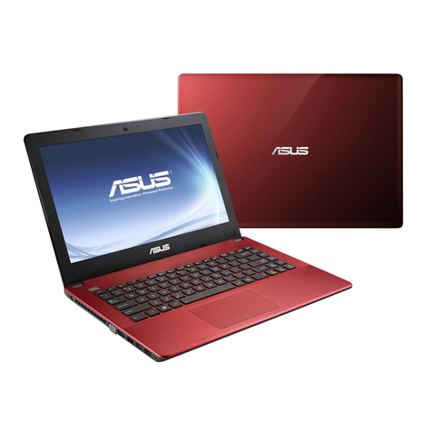
Asus C403NA FQ0019 User manual

Service Overview
1-1 V1.0
C403NA Service manual
COPYRIGHT INFORMATION
No part of this manual, including the products and software described in it, may be reproduced,
transmitted, transcribed, stored in a retrieval system, or translated into any language in any form or by
any means, except documentation kept by the purchaser for backup purposes, without the express
written permission of ASUSTeK COMPUTER INC.("ASUS").
ASUS PROVIDES THIS MANUAL "AS IS"WITHOUT WARRANTY OF ANY KIND, EITHER
EXPRESS OR IMPLIED, INCLUDING BUT NOT LIMITED TO THE IMPLIED
WARRANTIES OR CONDITIONS OF MERCHANTABILITY OR FITNESS FOR A
PARTICULAR PURPOSE. IN NO EVENT SHALL ASUS, ITS DIRECTORS, OFFICERS,
EMPLOYEES OR AGENTS BE LIABLE FOR ANY INDIRECT, SPECIAL, INCIDENTAL, OR
CONSEQUENTIAL DAMAGES (INCLUDING DAMAGES FOR LOSS OF PROFITS, LOSS OF
BUSINESS, LOSS OF USE OR DATA, INTERRUPTION OF BUSINESS AND THE LIKE),
EVEN IF ASUS HAS BEEN ADVISED OF THE POSSIBILITY OF SUCH DAMAGES
ARISING FROM ANY DEFECT OR ERROR INTHIS MANUAL OR PRODUCT.
Products and corporate names appearing in this manual may or may not be registered trademarks or
copyrights of their respective companies, and are used only for identification or explanation and to the
owners' benefit, without intent to infringe.
SPECIFICATIONS AND INFORMATION CONTAINED IN THIS MANUAL ARE
FURNISHED FOR INFORMATIONAL USE ONLY, AND ARE SUBJECTTO CHANGE AT
ANY TIME WITHOUT NOTICE, AND SHOULD NOT BE CONSTRUED AS A
COMMITMENT BY ASUS. ASUS ASSUMES NO RESPONSIBILITY OR LIABILITY FOR ANY
ERRORS OR INACCURACIES THAT MAY APPEAR IN THIS MANUAL, INCLUDING THE
PRODUCTS AND SOFTWARE DESCRIBED IN IT.
Copyright ○
c2023 ASUSTeK COMPUTER INC. All Rights Reserved.
LIMITATION OF LIABILITY
Circumstances may arise where because of a default on ASUS' part or other liability, you are entitled to
recover damages from ASUS. In each such instance, regardless of the basis on which you are entitled to
claim damages from ASUS, ASUS is liable for no more than damages for bodily injury (including death)
and damage to real property and tangible personal property; or any other actual and direct damages
resulted from omission or failure of performing legal duties under this Warranty Statement, up to the
listed contract price of each product.
ASUS will only be responsible for or indemnify you for loss, damages or claims based in contract, tort or
infringement under this Warranty Statement.

Service Overview
1-2 V1.0
This limit also applies to ASUS' suppliers and its reseller. It is the maximum for which ASUS, its
suppliers, and your reseller are collectively responsible.
UNDER NO CIRCUMSTANCES IS ASUS LIABLE FOR ANY OF THE FOLLOWING: (1)
THIRD-PARTY CLAIMS AGAINSTYOU FOR DAMAGES; (2) LOSS OF, OR DAMAGE
TO,YOUR RECORDS OR DATA; OR (3) SPECIAL, INCIDENTAL, OR INDIRECT DAMAGES
OR FOR ANY ECONOMIC CONSEQUENTIAL DAMAGES (INCLUDING LOST PROFITS
OR SAVINGS), EVEN IF ASUS, ITS SUPPLIERS OR YOUR RESELLER IS INFORMED OF
THEIR POSSIBILITY.
SERVICE AND SUPPORT
Visit our multi-language website at https://www.asus.com/support/
Disclaimer
ASUS is not responsible for direct, indirect, intentional or unintentional damages resulting from
improper installation and operation.
Safety precautions
Before handling components, use a grounded wrist strap or touch a safely grounded object to avoid
damaging them due to static electricity.
Keep liquids or moisture away from your Notebook PC to avoid short circuits.
Remove rings, watches, and any other metal objects from your hands.
Hold components by the edges to avoid touching the ICs.
Properly install all components before connecting the AC power. Do not use power adapters or
batteries from other devices to reduce the risk of injury to persons due to fire or explosion. Use only
certified power adapters or batteries supplied by the manufacturer or authorized retailers.
Detach all clips or flaps before removing cables to prevent damage.
Disconnect cables, connectors, and power plugs by pulling the plug evenly to avoid damage.
Use the correct screw models on your Notebook PC to prevent damage.
Confirm that the cable orientation is correct before connecting any cables.
Fully remove all adhesive residue after removing and before installing any components.
Photograph the appearance of cables, cable routing,connectors, and screws for later reference
before proceeding with each step.

Service Overview
1-3 V1.0
Service Overview
Carefully read through this chapter for a look at various components of
the notebook before performing any service and repairs.
o provide the best service and support for the ASUS C403 series Notebook, we have
provided the below information for technicians from distributors and resellers to
perform the complete notebook disassembly and assembly. But before performing the
procedures, please be sure to read through the overview in this chapter for component
overview to avoid any unwarranted damages to the notebook’s hardware.
The following chapter includes:
C403 Overview
Components
C403 Overview
In this section, an overview for the C403 long with its components , will be presented.
C403 Overview
The illustrations below show the notebook’s overview from front view, right side view, and
left side view. Most of the parts will be discussed in this manual.
TOP View
T
O V E R V I E W

Service Overview
V1.0
1 - 4
1. Microphone
2. Camera indicator
3. Camera
4. Display panel
5. Keyboard
6. Touchpad
7. Power button

Disassembly Procedure
V1.0
2 - 5
Bottom View
1. Audio speakers
Right View
1.USB 3.1 Gen 1 port
2. USB 3.1 Gen 1 Type-C port/Display Port/ Power (DC) input port combo port
3.Kensington Security Slot
Left View
1. USB 3.1 Gen 1 Type-C port/Display Port/ Power (DC) input port combo port
2. Two-color battery charge indicator
3. Micro SD card slot
4. Headphone/Headset jack
5. USB 3.1 Gen 1 port
BACK

Disassembly Procedure
V1.0
2 - 6
Components
The illustrations below show the components of the X430.
LCD
The illustration below shows the LCD.
LCD Bezel
The illustration below shows the LCD bezel.
LCD Cover
The illustration below shows the LCD cover.
C O M P O N E N T S
L C D C O V E R
L C D
L C D B E Z E L

Disassembly Procedure
V1.0
2 - 7
Top Case
The illustration below shows the top case.
Bottom Case
The illustration below shows the bottom case.
Thermal Module
The illustration below shows the thermal module.
T O P C A S E
B O T T O M C A S E
T H E R M AL
M O D U L E

Disassembly Procedure
V1.0
2 - 8
Main Board
The illustration below shows the main board.
Battery Pack
The illustration below shows the battery pack.
M A I N B O A R D
B A T T E R Y

Disassembly Procedure
V1.0
2 - 9
IO Board
The illustration below shows the IO board.
Touchpad
The illustration below shows the touchpad.
Camera
The illustration below shows the camera.
IO B O A R D
C A M E R A
T O U C H P A D

Disassembly Procedure
V1.0
2 - 11
Disassembly Procedure
Please follow the information provided in this section to perform the complete disassembly procedure of the
Notebook. Be sure to use proper tools described before.
SUS C403NA notebook consists of various modules. This chapter describes the procedure for the
complete notebook disassembly and assembly (Assemble document please look up from the last
page). In addition, in between procedures, the detailed disassembly procedure of individual modules will
be provided for your service needs.
The disassembly procedure consists of the following steps:
Appropriate Tools
Touch Pad Module
Battery Module
Thermal &Motherboard Module
IO Board Module
Speaker Module
LCD Module
Camera Module
Gap Step
A

Disassembly Procedure
V1.0
2 - 12
Appropriate Tools
The illustrations below show the appropriate tools that should be used for the notebook’s service and repair.
Cross Screwdriver
Please according to different screw specification and choose different screwdriver and head.
Below photos are for reference only.
Use a cross screwdriver to fasten/remove screws.
Plastic Blade

Disassembly Procedure
V1.0
2 - 14
Touch pad Module
The illustrations below show how to remove and disassemble the Touch PAD Module.
Remove Touch Pad Module
1. Follow below numbers to remove 10 screws on the Bottom case module.
Assembly Notice: Follow the reverse numbers to lock screws.
Screw tightening torque (Kg F-cm): 2 KG±0.2kgf.
M2.0* L9.0

Disassembly Procedure
V1.0
2 - 15
2. Use disassembly tool to pry up the BTM CASE DOOR ASSY
3. Remove the rest of 4 screws on bottom case ,remove battery connector cover ,
disconnect the Battery connector,KB and touchpad cable .
Assembly notice: Insert FFC to the bottom until just accord with the line when lock the latch
Screw tightening torque (Kg F-cm): 2 KG±0.2kgf.

Disassembly Procedure
V1.0
2 - 16
Notice: Before disassembly, please be sure to pull out adapter and disconnect the battery more than ten seconds in
order to avoid IC damage.
M2.0* L2.5

Disassembly Procedure
V1.0
2 - 17
4. Use disassembly tool to pry up the sides of the top case.
4.Remove gasket from touchpad and then remove 3 screws on the touchpad. Then disconnect the TP FFC
on the touchpad
Assembly Notice: follow the reverse numbers to lock screws.
Screw tightening torque: 2.0±0.20 kgf-cm

Disassembly Procedure
V1.0
2 - 18
M2.0* L2.5

Disassembly Procedure
V1.0
2 - 19
Assembly notice: Please change new one, If FFC is damage during disassembly.
Here are some samples of FFC damage:
BACK
Parts
C403NA-1A TOP CASE MODULE// *1
C403NA-1A BTM CASE DOOR ASSY// *1
TOUCHPAD FOR C300SA//ELAN/SA461D-1005*1
C403NA TP FFC 6P 0.5MM L232MM//XINYA/X18AA1-5850-HF*1
C403NA-1A BTM BATTERY DOOR*1
Total screw *17
(Actual part name depends on different SKU.)

Disassembly Procedure
V1.0
2 - 20
Battery Module
The illustration below shows how to remove the battery module.
Remove Battery Module
Remove 5 screws on the Battery module
Assembly Notice: Follow the reverse numbers to lock screws.
Screw tightening torque (Kg F-cm): 2KG±0.2kgf.
Table of contents
Other Asus Laptop manuals

Asus
Asus Eee PC 900 User manual

Asus
Asus G53SW User manual

Asus
Asus Q536FD-BI7T15 Guide

Asus
Asus Eee PC 900HD XP Operating manual

Asus
Asus X53TA User manual

Asus
Asus L4E User manual

Asus
Asus PRO P3540FA Guide

Asus
Asus V1Jp Instructions for use

Asus
Asus Eee PC 2G Series User manual

Asus
Asus ROG STRIX G532LWS User manual