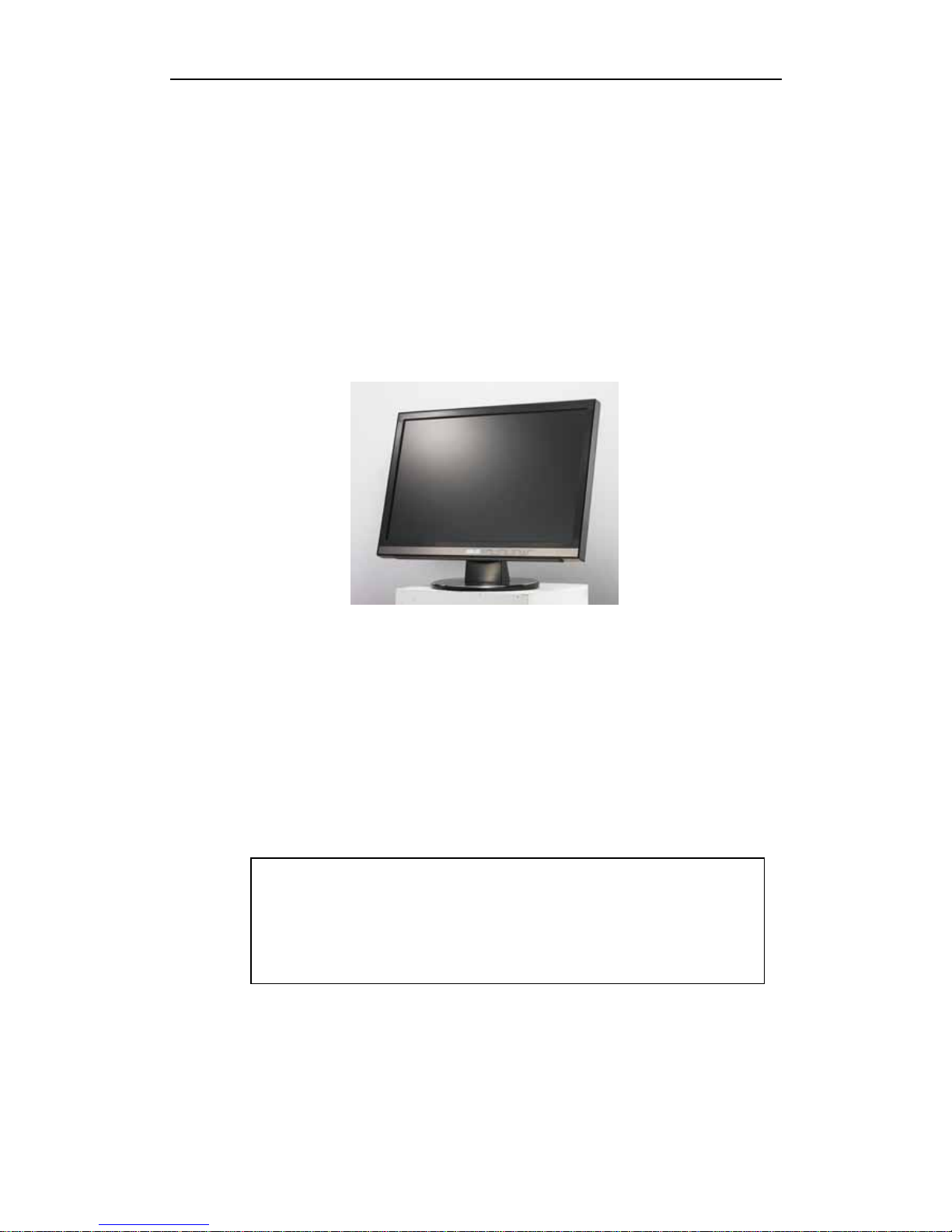
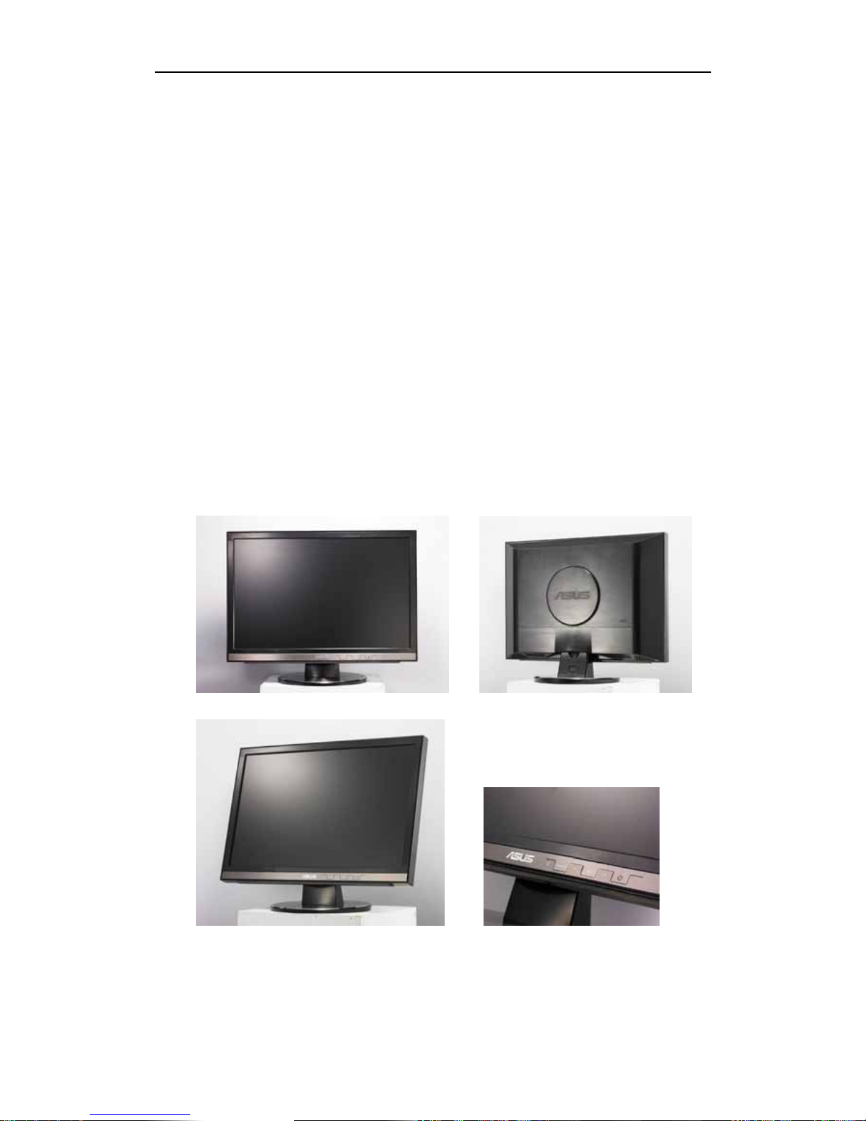
Asus MW221U/201U User manual

LCD Monitor Service Guide
for
L2 (Module) Repair
Model: MW221U/201U
V1.0
RESTRICTIONS ON USE OF MATERIALS
This manual is only for ASUS authorized service centers to repair ASUS
LCD product. The documents are provided as is and no copy, reproduction
or transfer shall be made without first acquiring prior written approval from
ASUSTEK. All rights reserved

2
Release Version List
Version Issue Date Remarks
V1.0 2006.09.05 First Release

3
Index
I. MW201 LCD Monitor Overview ................................................................1
II. Product Specification ................................................................................2
III. MMI...........................................................................................................3
Front side..................................................................................................3
Back side ..................................................................................................5
IV. Menu & Operating Mode...........................................................................6
V. Disassembly & Assembly..........................................................................7
1. Precaution .........................................................................................7
2. Suggest Tools ....................................................................................8
3. Disassembly Procedure.....................................................................9
3.1 Stand Subsystem................................................................................10
3.2 Board Subsystem ...............................................................................11
3.3 Panel Subsystem................................................................................16
3.4 Bezel Subsystem................................................................................18
4. Assemble Procedure .......................................................................20
4.1 Bezel Subsystem................................................................................21
4.2Panel Subsystem ................................................................................23
4.3Board Subsystem................................................................................25
4.4Stand Subsystem ................................................................................30
9. HW Block Diagram .................................................................................31

I. MW221/201 LCD Monitor Overview
Main product features include:
z16:10 wide display format
z1680*1050 WSXGA+ High Resolution
zTrace-Free Technology provide 2ms(GTG) Response Time
z330nits Brightness with 800:1 Contrast Ratio(MW221U)
z170/160 Degree Wide Viewing Angle
zSPLENDIDTM Video Intelligence Technology
zHDCP function for digital signals with DVI input
z5 Video Preset Modes (hotkey) & 3 Skin-tones
zDual Signal Input (DVI-D and D-Sub)
zDVI cable/D-Sub cable provided
zBuilt-in Stereo Speakers with Earphone Output
zSophisticated Aluminum plate to dress monitor outlook
zShining high-tech feeling key button
zCable cover for great outlook no matter which position
zVESA Wall Mounting compatible

2
II. Product Specification
Technical Specification MW221 MW201
Panel Size 22’’ Wide 20.1’’ Wide
Response Time 2ms(Gray to Gray)
Brightness (Max.) 300cd/m2
Contrast Ratio (Max.) 700:1
Viewing Angle (H/V) 170/160 170/150
Max. Resolution WSXGA+1680x1050
Pixel Pitch 0.282mm 0.258mm
Panel
Display Color 16.2M
Splendid (Video Intelligence) Yes
Analog 15-Pin D-Sub
Digital 24-Pin DVI-D
Inputs
PC Audio Line-in 3.5mm mini jack
Speaker 1W x 2 Stereo, RMS
Output Earphone 3.5mm mini jack
Tile +20~-5
Wall Mounting (VESA) Yes(100mm)
ME
Color Black
Security Kensington lock Yes
Power Supply AC: 100~240V
Power on mode <65W
Power
Standy by mode <2W
Net (WxHxD) 514x401x228 mm 476x378x228 mm
Dimension Packing (WxHxD) 610x510x220 mm 566x465x203 mm
Net 6.1kg 5.7kg
Weight Gross 8.1kg 7.1kg
Accessory DVI,D-sub cable, Audio cable, Power
cord, Quick Start Guide,User manual
Regulation Approval
Energy Star 2006, UL/cUL, CB, CE,
FCC, CCC, BSMI, Gost-R, C-Tick,
MIC,WHQL

3
III.MMI
Front side
1. Headphone port This port connects a headphone with a stereo
mini-plug (3.5mm).
zThe headphone port is under the icon
zThe headphone is purchased separately,
2. SPLENDID Button:
zUse this hotkey to switch from five video preset modes (Game Mode,
Night View Mode, Scenery Mode, Standard Mode, and Theater Mode)
with SPLENDID™ Video Enhancement Technology.
zExit the OSD menu or go back to the previous menu as the OSD menu
is active.
zAutomatically adjust the image to its optimized position, clock, and
phase by pressing this button for 2-4 seconds.
3. ◄−Button:
zPress this button to decrease the value of the function selected or
move left/up to the previous function.
zThis is also a hotkey for Volume adjustment.

4
4. MENU Button:
zPress this button to enter/select the icon (function) highlighted while
the OSD is activated.
5.+►Button:
zPress this button to increase the value of the function selected or move
right/down to the next function.
zThis is also a hotkey for Brightness adjustment.
6. Power button/power indicator
zPress this button to turn the monitor on/off
zThe color definition of the power indicator is as the below table.
LED Status Description
Blue Power ON
Amber Standby mode
OFF Power OFF

5
Back side
Rear Connectors (From left to right)
1. PWR port. This port connects the power connector from the bundled
power cord.
2. Audio-in port. This port connects PC audio source by the bundled audio
cable.
3. DVI port. This 24-pin port is for PC (Personal Computer) DVI-D digital
signal connection.
4. VGA port. This 15-pin port is for PC VGA connection.
Rear
Connectors

6
IV. Menu & Operating Mode
Menu
Splendid Image Color
(1) Scenery Mode
(2) Standard Mode
(3) Theater Mode
(4) Game Mode
(5) Night View Mode
(1) Brightness
(2) Contrast
(3) Sharpness
(4) Saturation
(5) Position (For VGA only)
(6) Focus (For VGA only)
(1) Color Temp.
(2)Skin Tone
Input Select System Setup
(1) <VGA>
(2) <DVI>
(1) Volume
(2) OSD Setup
(3) Language
(4) Information
(5) Reset
Supported Operating Mode
Standard Vertical
Frequency
Pixel
Frequency Resolution Horizontal
Frequency
DOS 70Hz 28.32MHz 720 x 400 31.47KHz
60Hz 25.18MHz 640 x 480 31.47KHz
72Hz 31.50MHz 640 x 480 37.90KHz
VGA
75Hz 31.50MHz 640 x 480 37.50KHz
56Hz 36.00MHz 800 x 600 35.16KHz
60Hz 40.00MHz 800 x 600 37.90KHz
72Hz 50.00MHz 800 x 600 48.10KHz
SVGA
75Hz 49.50MHz 800 x 600 46.90KHz
60Hz 65.00MHz 1024 x 768 48.40KHz
70Hz 75.00MHz 1024 x 768 56.50KHz
XGA
75Hz 78.75MHz 1024 x 768 60.02KHz
60Hz 108.00MHz 1280x1024 64.00KHzSXGA
75Hz 135.00MHz 1280x1024 80.00KHz
VESA 75Hz 108.00MHz 1152 x 864 67.50KHz
VESA 60Hz 106.00MHz 1440 x 900 55.94KHz
VESA
(Primary)
60Hz 146.25MHz 1680x1050 65.29KHz

7
V. Disassembly & Assembly
1. Precaution
Please read the precautions as follows to prevent any damages to the LCD
Monitor and also select the appropriate tools for disassembly and re-assembly.
Make sure all power connection is removed. Be sure that the LCD Monitor
is in power off status.
Prepare soft cloth and sponge as working platform to place LCD monitor
horizontally.
Hold LCD by the side carefully and DON’T touch or press panel directly.
Remove all rings, watches and any other metal objects from your hands
which possible to cause scratch.
Always wear a ground strap or anti-static glove to protect the parts from
static discharge. ESD (electro-static discharge) protection is required to
guarantee the safety of product and personnel.

8
2. Suggest Tools
Here are some tools that can be used for the LCD monitor’s service and repair.
Philips-head Screwdriver
Use a Philips-head screwdriver to fasten/remove the K- or B-typed screws
P/N:N/A
Gloves
To protect LCD Panel and your hand
P/N: (L) 16-003300131 (M) 16-003300130
C/D Disassembly Tool
Use C/D Disassembly Tool to open cosmetic cover and avoid scratch.
P/N: 13GV0400PZZZZ
Spacer Screwdriver
Use a spacer screwdriver to fasten/remove spacer screws or hex screws.
P/N: N/A

9
3. Disassembly Procedure
Information in this section is to perform the disassembly procedure of the LCD
monitor. Depending on the failures, replace the defective parts accordingly.
Asus MW221/201 LCD Monitor consists of various subsystems. This section
describes the procedures for LCD monitor disassembly. In addition, the
detailed disassembly procedures of individual subsystem will be provided for
your service needs.
The disassembly procedure consists of the following steps:
3.1 Stand Subsystem
3.2 Board Subsystem
3.3 Panel Subsystem
3.4 Bezel Subsystem

10
3.1 Stand Subsystem
1. Press the button on STAND, and then pull down to dismount BASE.
2. Release 3 screws on STAND.
3. Pull down STAND to dismount.

11
3.2 Board Subsystem
Back Cover
1. Release 4 screws on the BACK COVER.
2. Press the latch to dismount VESA COVER.
3. Following the steps, open all latches at four sides of BEZEL, and then take
away Back Cover
.
1
4
3
2

12
Shielding
1. Remove 6 screws on the MAIN SHIELDING.
.
2. Pull down to remove MAIN SHIELDING.
Cables
1. Unplug AUDIO CABLE.

13
2. Disconnect POWER CABLE with MAIN BOARD.
3. Unplug KEY BOARD CABLE。
Boards
1. Release 2 screws on AUDIO BOARD to dismount.
2. Remove 5 screws on MAIN BOARD.

14
3. Remove 4 screws on VGA PORT and DVI PORT.
4. Pull out the MAIN BOARD slightly, but do not remove it.
5. Unplug the LVDS CABLE,and then take away MAIN BOARD.
6. Unplug LAMP CABLES.

15
7. Remove 5 screws on POWER BOARD.
8. Remove POWER BOARD.

16
3.3 Panel Subsystem
1. Remove 2 screws on I/O BRACKET, and then pull down to dismount it.
2. Remove 3 pieces of TAPE.
3. Release 2 screws on PANEL FRAME.

17
4. Separate LCD PANEL form BEZEL.
5. Loose 4 screws on left and right side of LCD PANEL.
6. Separate PANEL FRAME from LCD PANEL.
This manual suits for next models
2
Table of contents
Other Asus Monitor manuals

Asus
Asus VG259QMY Series User manual

Asus
Asus VK221D Reference guide

Asus
Asus VG258QM Series User manual

Asus
Asus VH232H - 23" LCD Monitor User manual

Asus
Asus LS201 User manual

Asus
Asus PB328Q User manual

Asus
Asus VW202xR Series User manual

Asus
Asus ROG strix XG256Q User manual

Asus
Asus MZ27AQ Series User manual

Asus
Asus VW199T User manual

Asus
Asus VY279HE-W User manual

Asus
Asus PA328 Series User manual

Asus
Asus ZenScreen Go MB16AP User manual

Asus
Asus VP239T User manual

Asus
Asus PA248Q User manual

Asus
Asus ProArt PA348CGV Series User manual

Asus
Asus VG278HE Series User manual

Asus
Asus MS228H Series User manual

Asus
Asus VY229HE Series User manual

Asus
Asus BE229 Series User manual