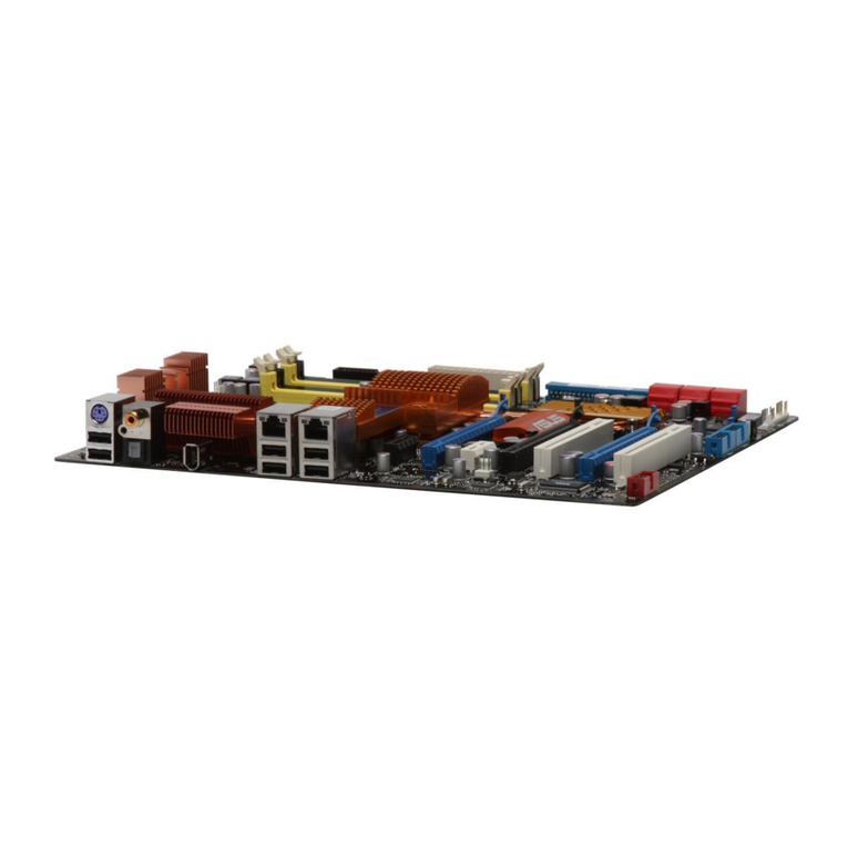
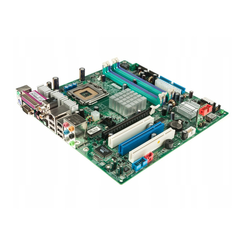
Asus MAXIMUS III FORMULA User manual

Motherboard
Maximus III
Formula

ii
E4884
First Edition
July 2009
Copyright © 2009 ASUSTeK COMPUTER INC. All Rights Reserved.
No part of this manual, including the products and software described in it, may be reproduced,
transmitted, transcribed, stored in a retrieval system, or translated into any language in any form or by any
means, except documentation kept by the purchaser for backup purposes, without the express written
permission of ASUSTeK COMPUTER INC. (“ASUS”).
product is defaced or missing.
ASUS PROVIDES THIS MANUAL “AS IS” WITHOUT WARRANTY OF ANY KIND, EITHER EXPRESS
OR IMPLIED, INCLUDING BUT NOT LIMITED TO THE IMPLIED WARRANTIES OR CONDITIONS OF
MERCHANTABILITY OR FITNESS FOR A PARTICULAR PURPOSE. IN NO EVENT SHALL ASUS, ITS
DIRECTORS, OFFICERS, EMPLOYEES OR AGENTS BE LIABLE FOR ANY INDIRECT, SPECIAL,
INCIDENTAL, OR CONSEQUENTIAL DAMAGES (INCLUDING DAMAGES FOR LOSS OF PROFITS,
LOSS OF BUSINESS, LOSS OF USE OR DATA, INTERRUPTION OF BUSINESS AND THE LIKE),
EVEN IF ASUS HAS BEEN ADVISED OF THE POSSIBILITY OF SUCH DAMAGES ARISING FROM ANY
DEFECT OR ERROR IN THIS MANUAL OR PRODUCT.
SPECIFICATIONS AND INFORMATION CONTAINED IN THIS MANUAL ARE FURNISHED FOR
INFORMATIONAL USE ONLY, AND ARE SUBJECT TO CHANGE AT ANY TIME WITHOUT NOTICE,
AND SHOULD NOT BE CONSTRUED AS A COMMITMENT BY ASUS. ASUS ASSUMES NO
RESPONSIBILITY OR LIABILITY FOR ANY ERRORS OR INACCURACIES THAT MAY APPEAR IN THIS
MANUAL, INCLUDING THE PRODUCTS AND SOFTWARE DESCRIBED IN IT.
Products and corporate names appearing in this manual may or may not be registered trademarks or

iii
Contents
Notices....................................................................................................... viii
Safety information ...................................................................................... ix
About this guide ......................................................................................... xi
....................................... xiii
Chapter 1: Product introduction
1.1 Welcome! ...................................................................................... 1-1
1.2 Package contents......................................................................... 1-1
1.3 Special features............................................................................ 1-2
1.3.1 Product highlights ........................................................... 1-2
1.3.2 ROG Intelligent Performance & Overclocking features... 1-3
1.3.3 ROG unique features ...................................................... 1-5
1.3.4 ASUS special features .................................................... 1-6
Chapter 2: Hardware information
2.1 Before you proceed ..................................................................... 2-1
2.2 Motherboard overview................................................................. 2-5
2.2.1 Motherboard layout ......................................................... 2-5
2.2.2 SupremeFX X-Fi audio card layout................................. 2-6
2.2.3 Layout contents............................................................... 2-6
2.2.4 Placement direction ........................................................ 2-7
2.2.5 Screw holes .................................................................... 2-7
2.3 Central Processing Unit (CPU) ................................................... 2-8
2.3.1 Installing the CPU ........................................................... 2-8
2.3.2 Installing the CPU heatsink and fan...............................2-11
2.3.3 Uninstalling the CPU heatsink and fan ......................... 2-12
2.4 System memory ......................................................................... 2-13
2.4.1 Overview ....................................................................... 2-13
.................................................. 2-14
2.4.3 Installing a DIMM .......................................................... 2-21
2.4.4 Removing a DIMM ........................................................ 2-21
2.5 Expansion slots.......................................................................... 2-22
2.5.1 Installing an expansion card ......................................... 2-22
..................................... 2-22
2.5.3 Interrupt assignments ................................................... 2-23
2.5.4 PCI slot ......................................................................... 2-24

iv
Contents
2.5.5 PCI Express x1 slots..................................................... 2-24
2.5.6 PCI Express x16 slot..................................................... 2-24
2.5.7 PCI Express 2.0 x16 slots............................................. 2-24
2.6 Jumper ........................................................................................ 2-26
2.7 I/O shield and Audio card Installation ...................................... 2-27
2.7.1 I/O shield Installation..................................................... 2-27
2.7.2 Audio card Installation................................................... 2-28
2.8 Connectors ................................................................................. 2-29
2.8.1 Rear panel connectors.................................................. 2-29
2.8.2 Internal connectors ....................................................... 2-31
2.8.3 Onboard switches ......................................................... 2-41
...................................................... 2-43
2.10 Turning off the computer........................................................... 2-44
2.10.1 Using the OS shut down function.................................. 2-44
2.10.2 Using the dual function power switch............................ 2-44
Chapter 3: BIOS setup
3.1 Managing and updating your BIOS ............................................ 3-1
3.1.1 ASUS Update utility ........................................................ 3-1
3.1.2 ASUS EZ Flash 2 utility................................................... 3-4
3.1.3 ASUS CrashFree BIOS 3 utility ...................................... 3-5
3.2 BIOS setup program .................................................................... 3-6
3.2.1 BIOS menu screen.......................................................... 3-7
3.2.2 Menu bar......................................................................... 3-7
3.2.3 Navigation keys............................................................... 3-7
3.2.4 Menu items ..................................................................... 3-8
3.2.5 Submenu items ............................................................... 3-8
......................................................... 3-8
3.2.7 Pop-up window ............................................................... 3-8
3.2.8 Scroll bar......................................................................... 3-8
3.2.9 General help ................................................................... 3-8
3.3 Extreme Tweaker menu ............................................................... 3-9
3.3.1 Ai Overclock Tuner [Auto] ............................................. 3-10
............... 3-10
3.3.3 OC From CPU/Memory Level Up [Auto] ....................... 3-10
3.3.4 CPU Ratio Setting [Auto] .............................................. 3-10

v
Contents
3.3.5 Intel(R) SpeedStep(TM) Tech [Enabled] ....................... 3-10
3.3.6 Intel(R) TurboMode Tech [Enabled] .............................. 3-10
3.3.7 BCLK Frequency [XXX] .................................................3-11
3.3.8 PCIE Frequency [XXX] ..................................................3-11
3.3.9 QPI Frequency [Auto] ....................................................3-11
3.3.10 DRAM Frequency [Auto] ................................................3-11
3.3.11 DRAM Timing Control ....................................................3-11
3.3.12 CPU Clock Amplitude [Auto] ......................................... 3-13
3.3.13 PCH Clock Amplitude [Auto] ......................................... 3-13
3.3.14 CPU Clock Skew [Auto] ................................................ 3-13
3.3.15 PCH Clock Skew [Auto] ................................................ 3-13
3.3.16 Extreme OV [Disabled] ................................................. 3-13
3.3.17 Full Phase Control [HW TEST] ..................................... 3-13
3.3.18 CPU Load-Line Calibration [Auto]................................. 3-14
3.3.19 CPU Voltage Mode [Offset] .......................................... 3-14
3.3.20 CPU Voltage [Auto] ...................................................... 3-14
3.3.21 CPU PLL Voltage [Auto]................................................ 3-14
3.3.22 IMC Voltage [Auto] ....................................................... 3-14
3.3.23 PCH Voltage [Auto] ....................................................... 3-14
3.3.24 DRAM Voltage [Auto] .................................................... 3-15
3.3.25 DRAM DATA REF Voltage on CHA/B [Auto] ................. 3-15
3.3.26 DRAM CTRL REF Voltage on CHA/B [Auto]................. 3-15
3.3.27 Keyboard TweakIt Control [Disabled]............................ 3-15
3.3.28 CPU Spread Spectrum [Auto] ....................................... 3-15
3.3.29 PCIE Spread Spectrum [Auto] ...................................... 3-15
3.4 Main menu .................................................................................. 3-16
3.4.1 System Time [xx:xx:xx] ................................................. 3-16
3.4.2 System Date [Day xx/xx/xxxx]....................................... 3-16
3.4.3 Language [English] ....................................................... 3-16
3.4.4 SATA 1–6.........................................................................................3-17
................................................... 3-19
....................................................... 3-20
3.4.7 System Information ....................................................... 3-20
3.5 Advanced menu ......................................................................... 3-21
........................................................ 3-21

vi
Contents
3.5.2 Chipset.......................................................................... 3-24
...................................... 3-25
........................................................ 3-26
3.5.5 LED Control .................................................................. 3-27
....................................................... 3-28
3.5.7 ROG Connect ............................................................... 3-28
3.6 Power menu................................................................................ 3-29
3.6.1 Suspend Mode [Auto] ................................................... 3-29
3.6.2 Repost Video on S3 Resume [Disabled]....................... 3-29
3.6.3 ACPI 2.0 Support [Disabled] ......................................... 3-29
........................................................ 3-30
3.6.4 ACPI APIC Support [Enabled]....................................... 3-30
3.6.5 EuP Ready [Disabled]................................................... 3-30
3.6.7 Hardware Monitor ......................................................... 3-32
3.7 Boot menu .................................................................................. 3-35
3.7.1 Boot Device Priority ...................................................... 3-35
.......................................... 3-36
3.7.3 Security ......................................................................... 3-37
3.8 Tools menu ................................................................................. 3-39
........................................ 3-39
......................................................... 3-40
3.8.3 GO_Button File ............................................................. 3-42
3.8.4 AI NET 2........................................................................ 3-42
3.8.5 MemPerfect................................................................... 3-43
3.8.6 ASUS EZ Flash 2.......................................................... 3-43
3.9 Exit menu.................................................................................... 3-44
Chapter 4: Software support
4.1 Installing an operating system ................................................... 4-1
4.2 Support DVD information ............................................................ 4-1
4.2.1 Running the support DVD ............................................... 4-1
4.2.2 Drivers menu................................................................... 4-2
4.2.3 Utilities menu .................................................................. 4-3
4.2.4 Make disk menu.............................................................. 4-5
4.2.5 Manual menu .................................................................. 4-5
4.2.6 Video menu..................................................................... 4-6
vii
4.2.7 ASUS Contact information .............................................. 4-6
4.2.8 Other information ............................................................ 4-7
4.3 Software information ................................................................... 4-9
4.3.1 Sound Blaster X-Fi audio utility....................................... 4-9
4.3.2 ASUS PC Probe II......................................................... 4-13
4.3.3 ASUS AI Suite............................................................... 4-19
4.3.4 ASUS Fan Xpert ........................................................... 4-21
4.3.5 ASUS EPU-6 Engine .................................................... 4-22
4.3.6 TurboV EVO.................................................................. 4-23
.................................................................. 4-27
............................................................ 4-27
4.4.2 Installing Serial ATA hard disks ..................................... 4-28
4.4.3 Setting the RAID item in BIOS ...................................... 4-28
4.4.4 Intel®Matrix Storage Manager option ROM utility......... 4-28
4.5 Creating a RAID driver disk....................................................... 4-32
4.5.1 Creating a RAID driver disk without entering the OS.... 4-32
4.5.2 Creating a RAID driver disk in Windows®...................... 4-32
4.5.3 Installing the RAID driver during
Windows®OS installation.............................................. 4-33
....................................... 4-33
Chapter 5: ATI®CrossFireX™ technology support
5.1 ATI®CrossFireX™ technology .................................................... 5-1
5.1.1 Requirements.................................................................. 5-1
5.1.2 Before you begin............................................................. 5-1
5.1.3 Installing CrossFireX graphics cards .............................. 5-2
5.1.4 Installing the device drivers............................................. 5-3
5.1.5 Enabling the ATI®CrossFireX™ technology ................... 5-3
5.2 NVIDIA®SLI™ technology ........................................................... 5-5
5.2.1 Requirements.................................................................. 5-5
5.2.2 Installing two SLI-ready graphics cards .......................... 5-5
5.2.3 Installing the device drivers............................................. 5-6
5.2.4 Enabling the NVIDIA®SLI™ technology ......................... 5-6
Appendix: Debug code table

viii
Notices
Federal Communications Commission Statement
This device complies with Part 15 of the FCC Rules. Operation is subject to the
following two conditions:
• This device may not cause harmful interference, and
• This device must accept any interference received including interference that
may cause undesired operation.
This equipment has been tested and found to comply with the limits for a
Class B digital device, pursuant to Part 15 of the FCC Rules. These limits are
designed to provide reasonable protection against harmful interference in a
residential installation. This equipment generates, uses and can radiate radio
instructions, may cause harmful interference to radio communications. However,
there is no guarantee that interference will not occur in a particular installation. If
this equipment does cause harmful interference to radio or television reception,
which can be determined by turning the equipment off and on, the user is
encouraged to try to correct the interference by one or more of the following
measures:
• Reorient or relocate the receiving antenna.
• Increase the separation between the equipment and receiver.
• Connect the equipment to an outlet on a circuit different from that to which the
receiver is connected.
• Consult the dealer or an experienced radio/TV technician for help.
Canadian Department of Communications Statement
This digital apparatus does not exceed the Class B limits for radio noise emissions
from digital apparatus set out in the Radio Interference Regulations of the
Canadian Department of Communications.
This class B digital apparatus complies with Canadian ICES-003.
The use of shielded cables for connection of the monitor to the graphics card is
to this unit not expressly approved by the party responsible for compliance
REACH
Restriction of Chemicals) regulatory framework, we published the chemical
substances in our products at ASUS website at http://green.asus.com/english/
REACH.htm.

ix
Safety information
Electrical safety
electrical outlet before relocating the system.
• When adding or removing devices to or from the system, ensure that the power
cables for the devices are unplugged before the signal cables are connected. If
possible, disconnect all power cables from the existing system before you add
a device.
• Before connecting or removing signal cables from the motherboard, ensure
that all power cables are unplugged.
• Seek professional assistance before using an adapter or extension cord.
These devices could interrupt the grounding circuit.
• Ensure that your power supply is set to the correct voltage in your area. If you
are not sure about the voltage of the electrical outlet you are using, contact
your local power company.
service technician or your retailer.
• The optical S/PDIF is an optional component (may or may not be included in
INVISIBLE LASER RADIATION, AVOID EXPOSURE TO BEAM.
substances into the environment.
• Never dispose of the battery with your regular household waste. Take it to a
• Never replace the battery with an incorrect battery type.
• RISK OF EXPLOSION IF BATTERY IS REPLACED BY AN INCORRECT
TYPE.
• DISPOSE OF USED BATTERIES ACCORDING TO THE ABOVE
BATTERY-RELATED INSTRUCTIONS.

x
Operation safety
• Before installing the motherboard and adding devices on it, carefully read all
the manuals that came with the package.
• Before using the product, ensure all cables are correctly connected and the
power cables are not damaged. If you detect any damage, contact your dealer
immediately.
• To avoid short circuits, keep paper clips, screws, and staples away from
connectors, slots, sockets and circuitry.
• Avoid dust, humidity, and temperature extremes. Do not place the product in
any area where it may become wet.
This motherboard should only be used in environments with ambient
temperatures between 5oC (41oF) and 40oC (104oF).
• Place the product on a stable surface.
service technician or your retailer.
DO NOT throw the motherboard in municipal waste. This product has been
designed to enable proper reuse of parts and recycling. This symbol of the
crossed out wheeled bin indicates that the product (electrical and electronic
equipment) should not be placed in municipal waste. Check local regulations for
disposal of electronic products.
DO NOT throw the mercury-containing button cell battery in municipal waste.
This symbol of the crossed out wheeled bin indicates that the battery should not
be placed in municipal waste.

xi
Refer to the following sources for additional information and for product and
software updates.
1. ASUS websites
The ASUS website provides updated information on ASUS hardware and
software products. Refer to the ASUS contact information.
2. Optional documentation
Your product package may include optional documentation, such as warranty
part of the standard package.
About this guide
the motherboard.
How this guide is organized
This guide contains the following parts:
• Chapter 1: Product introduction
This chapter describes the features of the motherboard and the new
technology it supports.
• Chapter 2: Hardware information
This chapter lists the hardware setup procedures that you have to perform
when installing system components. It includes description of the switches,
jumpers, and connectors on the motherboard.
• Chapter 3: BIOS setup
This chapter tells how to change system settings through the BIOS Setup
menus. Detailed descriptions of the BIOS parameters are also provided.
• Chapter 4: Software support
This chapter describes the contents of the support DVD that comes with the
motherboard package and the software.
• Chapter 5: Multiple GPU technology support
®
CrossFireX™ and NVIDIA®SLI™ graphics cards.
• Appendix: Debug code table
The Appendix lists the debug code table for the LCD Poster.

xii
DANGER/WARNING: Information to prevent injury to yourself
when trying to complete a task.
CAUTION: Information to prevent damage to the components
when trying to complete a task.
NOTE: Tips and additional information to help you complete a
task.
IMPORTANT: Instructions that you MUST follow to complete a
task.
Conventions used in this guide
To ensure that you perform certain tasks properly, take note of the following
symbols used throughout this manual.
Typography
Bold text Indicates a menu or an item to select.
Italics
<Key> Keys enclosed in the less-than and greater-than sign
means that you must press the enclosed key.
Example: <Enter> means that you must press the
Enter or Return key.
<Key1+Key2+Key3> If you must press two or more keys simultaneously, the
key names are linked with a plus sign (+).
Example: <Ctrl+Alt+D>
Command Means that you must type the command exactly as
shown, then supply the required item or value enclosed
in brackets.
Example: At the DOS prompt, type the command line:
afudos /iMAIIIFOR.ROM

xiii
Maximus III Formula specications summary
CPU Supports the Intel®Core™i7 and Intel® Core™i5
Processor in the LGA1156 package
Supports Intel®Turbo Boost Technology
* Refer to www.asus.com for Intel CPU support list
Chipset Intel®P55 Express Chipset
Memory Dual channel memory architecture
4 x DIMM, max. 16GB, DDR3 2133(O.C.)/
non-ECC, un-buffered memory modulesnon-ECC, un-buffered memory modules
* Hyper DIMM support is subject to the physical
characteristics of individual CPUs.characteristics of individual CPUs.
* Supports Intel®
* Please refer to www.asus.com or user manual for the
Expansion Slots 3 x PCIe x16 slot
- 2 x PCIe 2.0 (red) support single at x16 or dual at x82 x PCIe 2.0 (red) support single at x16 or dual at x8
modemode
- 1 x PCIe 1.0 (white) supports at x4 mode1 x PCIe 1.0 (white) supports at x4 mode
2 x PCIe x1
2 x PCI 2.2
Multi-GPU Technology Supports NVIDIA®SLI™ Technology / ATI®CrossFireX™
TechnologyTechnology
Storage Intel®P55 Express Chipset built-in:
- 6 x SATA 3.0 Gb/s ports
- Intel Matrix Storage Technology supports RAID 0, 1,
5 and 10
JMicron®322 controller and 2 x JMicron®363 controllers:
- 2 x SATA 3.0 Gb/s port (red) supporting Hardware
RAID 0 and 1 (SPD_HDD1 + SPD_HDD2)
- 1 x External SATA 3.0 Gb/s port (SATA On-the-Go)
- 2 x SATA 3.0 Gb/s port (white) -SATA_ODD1 +
SATA_ODD2
LAN Realtek®RTL8110SC Gigabit LAN controller
GameFirst
SupremeFX X-Fi discrete audio card
- EAXEAX®Advanced™ HD 4.0
- X-Fi CMSSX-Fi CMSS®-3D
- Creative ALchemyCreative ALchemy
- Supports 1 x S/PDIF out headerSupports 1 x S/PDIF out header
- Supports Coaxial/Optical S/PDIF out ports on rearSupports Coaxial/Optical S/PDIF out ports on rear
- Blu-ray support
IEEE 1394a 2 x 1394a ports (1 port at back I/O, 1 port onboard)
(continued on the next page)

xiv
USB max. 14 USB 2.0 ports (5 ports at mid-board, 9 ports at
back panel)back panel)
ROG Exclusive
Overclocking Features
Extreme Engine Power Design
- 16-phase CPU power16-phase CPU power
- 3-phase VTT power3-phase VTT power
- 3-phase Memory power3-phase Memory power
ROG Connect
CPU Level Up
Memory Level Up
Speeding HDD
iROG
Extreme Tweaker
Loadline Calibration
Intelligent overclocking tools:
- ASUS AI Booster UtilityASUS AI Booster Utility
Overclocking Protection:
- COP EX (Component Overheat Protection - EX)COP EX (Component Overheat Protection - EX)
- Voltiminder LEDVoltiminder LED
- ASUS C.P.R.(CPU Parameter Recall)ASUS C.P.R.(CPU Parameter Recall)
Other Special Features MemOK!
MemPerfect
ProbeIt
Onboard Switches: Power / Reset / Clr CMOS (at rear)
Q-Fan Plus
ASUS EPU
ASUS MyLogo3
ASUS Fan Xpert
ASUS EZ Flash 2
ASUS CrashFree BIOS 3
ASUS Q-Connector
ASUS Q-LED (CPU, DRAM, VGA, Boot Device LED)
ASUS Q-Slot
ASUS Q-DIMM
BIOS Features 16Mb AMI BIOS, PnP, DMI2.0, WfM2.0, SM BIOS 2.4,
ACPI2.0a Multi-Language BIOS
Manageability WOL by PME, WOR by PME, PXE
Back Panel I/O Ports 1 x PS/2 Keyboard port (purple)
1 x External SATA port
1 x LAN (RJ45) port
9 x USB 2.0/1.1 ports (1 port for ROG Connect)
1 x ROG Connect On/Off switch
1 x IEEE1394a port
1 x Clr CMOS switch
(continued on the next page)
Maximus III Formula specications summary

xv
Internal I/O Connectors 3 x USB 2.0 connectors support additional 5 USB 2.0
ports (1 port reserved for ROG Connect @ rear)
10 x SATA connectors: 2 x Speeding HDD SATA
connectors (Red) / 2 x SATA_ODD (White) / 6 x
standard SATA connectors (Gray)
8 x Fan connectors: 1 x CPU / 1 x PWR / 3 x Chassis /
3 x Optional
3 x thermal sensor connectors
1 x IEEE1394a connector
1 x 24-pin ATX Power connector
1 x 8-pin ATX 12V Power connector
1 x En/Dis-able Clr CMOS header
5 x ProbeIt measurement points
1 x ROG light connector
1 x Go Button
System panel connector
Software Support DVD:
- Drivers and applications
Sound Blaster X-Fi Utility
Kaspersky®Anti-Virus
ASUS TurboV utility
ASUS PC Probe II
ASUS Update
ASUS AI Suite
Form Factor ATX Form Factor, 12”x 9.6” (30.5cm x 24.4cm)
Maximus III Formula specications summary

xvi

1
Chapter 1: Product
introduction
This chapter describes the motherboard
features and the new technologies
it supports.

ROG Maximus III Formula
Chapter summary 1
1.1 Welcome! ...................................................................................... 1-1
1.2 Package contents......................................................................... 1-1
1.3 Special features............................................................................ 1-2

ROG Maximus III Formula 1-1
1.1 Welcome!
Thank you for buying an ROG Maximus III Formula motherboard!
The motherboard delivers a host of new features and latest technologies, making it
another standout in the long line of ASUS quality motherboards!
Before you start installing the motherboard, and hardware devices on it, check the
items in your package with the list below.
1.2 Package contents
Check your motherboard package for the following items.
ROG Maximus III Formula Motherboard 1 x Multi-functional module (2-port USB 2.0
and 1-port ESATA)
SupremeFX X-Fi Audio Card 1 x ASUS Q-Shield (I/O shield)
3 x Serial ATA signal cables 1 x ROG Connect cable
1 x SLI Cable 1 x 2-in1 ASUS Q-Connector Kit
User Manual
1 x ROG theme label
1 x ROG cable label
(12-in-1)
Cable ties User Guide ROG Support DVD
• If any of the above items is damaged or missing, contact your retailer.
• The item illustrations in above table are for reference only. Actual product

1-2 Chapter 1: Product Introduction
1.3 Special features
1.3.1 Product highlights
Republic of Gamers
The Republic of Gamers consists only the best of the best. We offer the best
hardware engineering, the fastest performance, the most innovating ideas, and we
welcome the best gamers to join in. In the Republic of Gamers, mercy rules are
only for the weak, and bragging rights means everything. We believe in making
statements and we excel in competitions. If your character matches our trait, then
join the elite club, make your presence felt, in the Republic of Gamers.
Green ASUS
of creating environment-friendly and recyclable products/packaging to safeguard
Intel®
This motherboard supports the latest Intel®
package, which as memory and PCI Express controller integrated to support 2-
channel (4 DIMMs) DDR3 memory and 16 PCI Express 2.0 lanes, providing great
graphics performance. Intel®
Intel®P55 Chipset
The Intel®P55 Express Chipset is the latest one-chipset design to support the
latest 1156 socket Intel®
and stability.
SLI/CrossFireX On-Demand
SLI or CrossFireX? Fret no longer because with the ROG Maximus III Formula,
you'll be able to run both multi-GPU setups. The board features SLI/CrossFireX
path you take, you can be assured of jaw-dropping graphics at a level previously
unseen.
Table of contents
Other Asus Motherboard manuals

Asus
Asus VX97 User manual

Asus
Asus Z10PC-D8 Series User manual

Asus
Asus SK8N User manual

Asus
Asus SABERTOOTH X79 User manual

Asus
Asus Motherboard A8N-SLI Premium User manual

Asus
Asus PRIME A320M-E User manual

Asus
Asus P4B266-M User manual

Asus
Asus PRIME Z390-A User manual

Asus
Asus Prime H270-PRO User manual

Asus
Asus M3N78-AM User manual

Asus
Asus P3B-F User manual

Asus
Asus H310I-IM-A R2.0 User manual

Asus
Asus ROG STRIX Z490-H GAMING User manual

Asus
Asus MEW-B User manual

Asus
Asus M2N32-SLI PREMIUM VISTA User manual

Asus
Asus H61M-G User manual

Asus
Asus P8H61-M2/TPM/SI User manual

Asus
Asus Q170M-C User manual

Asus
Asus P10S-C/4L User manual

Asus
Asus ProArt B760-CREATOR User manual