Asus PRIME Z590-V User manual

Motherboard
PRIME Z590-V

ii
E17748
First Edition
January 2021
Copyright © 2021 ASUSTeK COMPUTER INC. All Rights Reserved.
No part of this manual, including the products and software described in it, may be reproduced,
transmitted, transcribed, stored in a retrieval system, or translated into any language in any form or by
any means, except documentation kept by the purchaser for backup purposes, without the express
written permission of ASUSTeK COMPUTER INC. (“ASUS”).
Product warranty or service will not be extended if: (1) the product is repaired, modified or altered, unless
such repair, modification of alteration is authorized in writing by ASUS; or (2) the serial number of the
product is defaced or missing.
ASUS PROVIDES THIS MANUAL “AS IS” WITHOUT WARRANTY OF ANY KIND, EITHER EXPRESS
OR IMPLIED, INCLUDING BUT NOT LIMITED TO THE IMPLIED WARRANTIES OR CONDITIONS OF
MERCHANTABILITY OR FITNESS FOR A PARTICULAR PURPOSE. IN NO EVENT SHALL ASUS, ITS
DIRECTORS, OFFICERS, EMPLOYEES OR AGENTS BE LIABLE FOR ANY INDIRECT, SPECIAL,
INCIDENTAL, OR CONSEQUENTIAL DAMAGES (INCLUDING DAMAGES FOR LOSS OF PROFITS,
LOSS OF BUSINESS, LOSS OF USE OR DATA, INTERRUPTION OF BUSINESS AND THE LIKE),
EVEN IF ASUS HAS BEEN ADVISED OF THE POSSIBILITY OF SUCH DAMAGES ARISING FROM
ANY DEFECT OR ERROR IN THIS MANUAL OR PRODUCT.
SPECIFICATIONS AND INFORMATION CONTAINED IN THIS MANUAL ARE FURNISHED FOR
INFORMATIONAL USE ONLY, AND ARE SUBJECT TO CHANGE AT ANY TIME WITHOUT NOTICE,
AND SHOULD NOT BE CONSTRUED AS A COMMITMENT BY ASUS. ASUS ASSUMES NO
RESPONSIBILITY OR LIABILITY FOR ANY ERRORS OR INACCURACIES THAT MAY APPEAR IN
THIS MANUAL, INCLUDING THE PRODUCTS AND SOFTWARE DESCRIBED IN IT.
Products and corporate names appearing in this manual may or may not be registered trademarks or
copyrights of their respective companies, and are used only for identification or explanation and to the
owners’ benefit, without intent to infringe.

iii
Contents
Safety information...................................................................................................... iv
About this guide.......................................................................................................... v
PRIME Z590-V specifications summary ................................................................... vi
Connectors with shared bandwidth .......................................................................... x
Package contents....................................................................................................... xi
Installation tools and components.......................................................................... xii
Chapter 1: Product Introduction
1.1 Before you proceed ...................................................................................1-1
1.2 Motherboard layout....................................................................................1-2
Chapter 2: Basic Installation
2.1 Building your PC system...........................................................................2-1
2.1.1 CPU installation........................................................................... 2-1
2.1.2 Cooling system installation..........................................................2-3
2.1.3 DIMM installation......................................................................... 2-5
2.1.4 M.2 installation ............................................................................ 2-6
2.1.5 Motherboard installation.............................................................. 2-7
2.1.6 ATX power connection................................................................ 2-9
2.1.7 SATA device connection........................................................... 2-10
2.1.8 Front I/O connector ................................................................... 2-11
2.1.9 Expansion card installation ....................................................... 2-12
2.2 Motherboard rear and audio connections ............................................. 2-14
2.2.1 Rear I/O connection .................................................................. 2-14
2.2.2 Audio I/O connections............................................................... 2-15
2.3 Starting up for the first time.................................................................... 2-18
2.4 Turning off the computer ........................................................................2-18
Chapter 3: BIOS and RAID Support
3.1 Knowing BIOS ............................................................................................3-1
3.2 BIOS Setup program.................................................................................. 3-2
3.3 ASUS EZ Flash 3 ........................................................................................3-3
3.4 ASUS CrashFree BIOS 3............................................................................3-4
3.5 RAID configurations ..................................................................................3-5
Appendix
Notices .................................................................................................................... A-1
Warranty................................................................................................................... A-6
ASUS contact information...................................................................................... A-8

iv
Safety information
Electrical safety
• To prevent electrical shock hazard, disconnect the power cable from the electrical
outlet before relocating the system.
• When adding or removing devices to or from the system, ensure that the power cables
for the devices are unplugged before the signal cables are connected. If possible,
disconnect all power cables from the existing system before you add a device.
• Before connecting or removing signal cables from the motherboard, ensure that all
power cables are unplugged.
• Seek professional assistance before using an adapter or extension cord. These
devices could interrupt the grounding circuit.
• Ensure that your power supply is set to the correct voltage in your area. If you are not
sure about the voltage of the electrical outlet you are using, contact your local power
company.
• If the power supply is broken, do not try to fix it by yourself. Contact a qualified service
technician or your retailer.
Operation safety
• Before installing the motherboard and adding devices on it, carefully read all the
manuals that came with the package.
• Before using the product, ensure all cables are correctly connected and the power
cables are not damaged. If you detect any damage, contact your dealer immediately.
• To avoid short circuits, keep paper clips, screws, and staples away from connectors,
slots, sockets and circuitry.
• Avoid dust, humidity, and temperature extremes. Do not place the product in any area
where it may become wet.
• Place the product on a stable surface.
• If you encounter technical problems with the product, contact a qualified service
technician or your retailer.
• Your motherboard should only be used in environments with ambient temperatures
between 0°C and 40°C.

v
About this guide
This user guide contains the information you need when installing and configuring the
motherboard.
How this guide is organized
This guide contains the following parts:
• Chapter 1: Product Introduction
This chapter describes the features of the motherboard and the new technology it
supports. It includes description of the switches, jumpers, and connectors on the
motherboard.
• Chapter 2: Basic Installation
This chapter lists the hardware setup procedures that you have to perform when
installing system components.
• Chapter 3: BIOS and RAID Support
This chapter tells how to boot into the BIOS, upgrade BIOS using the EZ Flash Utility
and support on RAID.
Where to find more information
Refer to the following sources for additional information and for product and software
updates.
1. ASUS website
The ASUS website (www.asus.com) provides updated information on ASUS hardware
and software products.
2. Optional documentation
Your product package may include optional documentation, such as warranty flyers,
that may have been added by your dealer. These documents are not part of the
standard package.
Conventions used in this guide
To ensure that you perform certain tasks properly, take note of the following symbols used
throughout this manual.
CAUTION: Information to prevent damage to the components and injuries to
yourself when trying to complete a task.
IMPORTANT: Instructions that you MUST follow to complete a task.
NOTE: Tips and additional information to help you complete a task.

vi
PRIME Z590-V specifications summary
CPU
Intel®Socket LGA1200 for 11th Gen Intel®Core™ Processors & 10th Gen
Intel®Core™, Pentium®Gold and Celeron®Processors*
Supports Intel®14 nm CPU
Supports Intel®Turbo Boost Technology 2.0 and Intel®Turbo Boost Max
Technology 3.0**
* Refer to www.asus.com for CPU support list.
** Intel®Turbo Boost Max Technology 3.0 support depends on the CPU types.
Chipset Intel®Z590 Chipset
Memory
4 x DIMM, Max. 128GB, DDR4 5133(OC)/5000(OC)/4800(OC)/4700(OC)/
4600(OC)/4500(OC)/4400(OC)/4266(OC)/4133(OC)/4000(OC)/
3866(OC)/3733(OC)/3600(OC)/3466(OC)/3400(OC)/3333(OC)/3200/
3000/2933/2800/2666/2400/2133 MHz Non-ECC, Un-buffered
Memory*
Dual Channel Memory Architecture
Supports Intel®Extreme Memory Profile (XMP)
OptiMem II
* 10th Gen Intel®Core™ i7/i9 processors support 2933/2800/2666/2400/2133
natively, others will run at the maximum transfer rate of DDR4 2666MHz.
* 11th Gen Intel®processors support 3200/2933/2800/2666/2400/2133 natively.
** Refer to www.asus.com for the Memory QVL (Qualified Vendors Lists), and
memory frequency support depends on the CPU types.
Graphics
1 x DisplayPort 1.4**
1 x HDMITM 1.4/2.0***
* Graphics specifications may vary between CPU types.
** Intel®11th & 10th Gen processors support DisplayPort 1.4 with max. resolution
of 4096 x 2304 @60Hz. Please refer to www.intel.com for any updates.
***Only Intel®11th Gen processors support HDMI™ 2.0 with max. resolution
of 4K@60Hz, others will only support HDMI™ 1.4 with max. resolution of
4K@30Hz. Please refer to www.intel.com for any updates.
Expansion Slots
Intel®11th & 10th Gen Processors*
1 x PCIe 4.0/3.0 x16 slot
- Intel®11th Gen processors support PCIe 4.0 x16 or x8/x8 or x8/x4/
x4 modes
- Intel®10th Gen processors support PCIe 3.0 x16 or x8/x8 or x8/x4/
x4 modes
Intel®Z590 Chipset
1 x PCIe 3.0 x16 slot (supports x4 mode)
3 x PCIe 3.0 x1 slots
* Supports PCIe bandwidth bifurcation for RAID on CPU function.
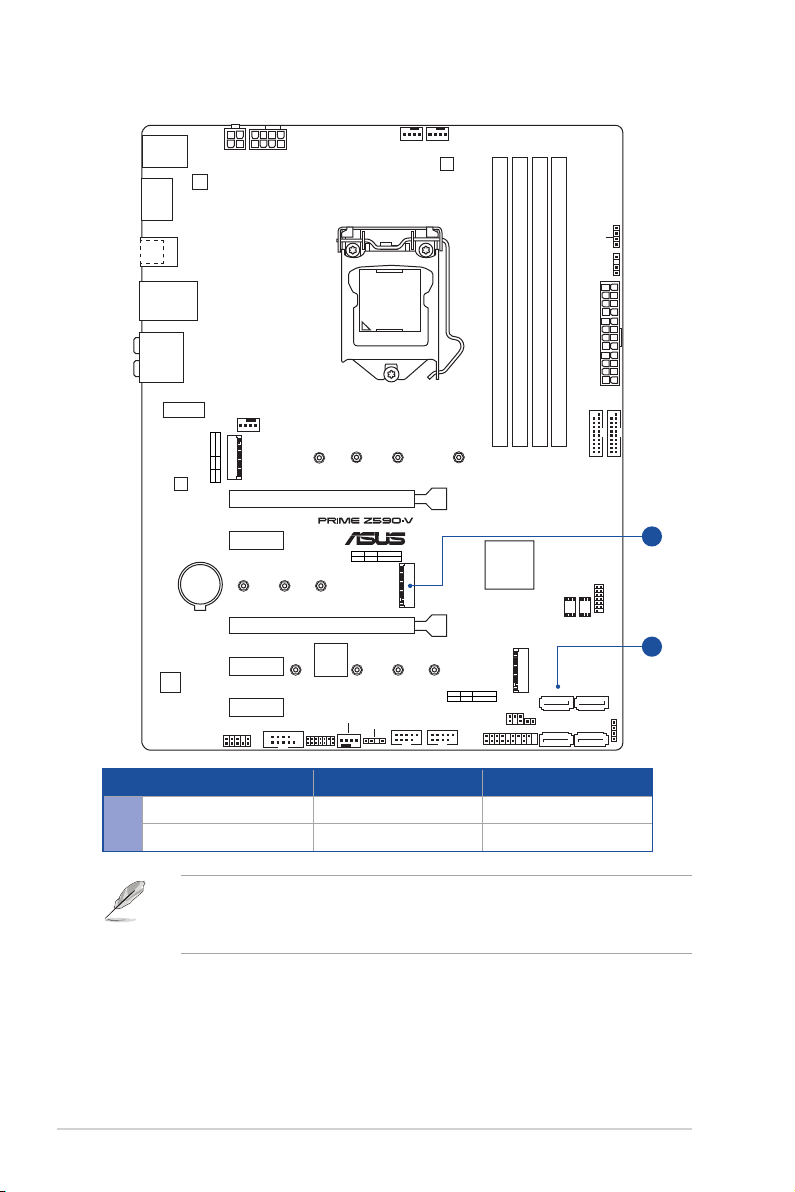
Storage
Total supports 3 x M.2 slots and 4 x SATA 6Gb/s ports
Intel®11th Gen Processors
M.2_1 slot (Key M), type 2242/2260/2280/22110
- Only Intel®11th Gen processors support PCIe 4.0 x4 mode, this slot
will be disabled for other CPUs
Intel®Z590 Chipset
M.2_2 slot (Key M), type 2242/2260/2280
(supports PCIe 3.0 x4 & SATA modes)*
M.2_3 slot (Key M), type 2242/2260/2280/22110
(supports PCIe 3.0 x4 & SATA modes)
4 x SATA 6Gb/s ports
(continued on the next page)

vii
PRIME Z590-V specifications summary
Storage
Raid function for PCIe mode SSD in Intel®Rapid Storage Technology is
available with either 1. Intel®SSDs installed in both CPU-attached and
PCH-attached slots, or 2. any other 3rd party SSDs installed in PCH-
attached slots.
To enable Intel®Optane™ Memory (Hybrid Storage device), it must be
installed in PCH-attached slots with Intel®Rapid Storage Technology.
* When a device in SATA mode is installed on the M.2_2 slot, SATA6G_2 port
cannot be used.
Ethernet 1 x Intel®I219-V 1Gb Ethernet
Wireless & Bluetooth V-M.2 slot only (Key E, CNVi & PCIe)*
* Wi-Fi module and vertical M.2 Key E bracket set are purchased separately.
USB
Rear USB (Total 6 ports)
1 x USB 3.2 Gen 2 port (1 x USB Type-C®)
1 x USB 3.2 Gen 2 port (1 x Type-A)
2 x USB 3.2 Gen 1 ports (2 x Type-A)
2 x USB 2.0 ports (2 x Type-A)
Front USB (Total 8 ports)
2 x USB 3.2 Gen 1 headers support additional 4 USB 3.2 Gen 1 ports
2 x USB 2.0 headers support additional 4 USB 2.0 ports*
* USB_E1 port, USB_E2 port, USB_E3 port and USB_E4 port share the
bandwidth.
Audio
Realtek ALC897 7.1 Surround Sound High Definition Audio CODEC
- Supports: Jack-detection, Multi-streaming, Front Panel Jack-retasking
- Supports up to 24-Bit/192kHz playback
Audio Features:
- Audio Shielding
- Rear optical S/PDIF out port
- Premium Japanese audio capacitors
- Dedicated audio PCB layers
Back Panel I/O Ports
1 x USB 3.2 Gen 2 port (1 x USB Type-C®)
1 x USB 3.2 Gen 2 port (1 x Type-A )
2 x USB 3.2 Gen 1 ports (2 x Type-A)
2 x USB 2.0 ports (2 x Type-A)
1 x DisplayPort
1 x HDMITM port
1 x V-M.2 slot (Key E)
1 x Intel®I219-V 1Gb Ethernet port
5 x Audio jacks
1 x Optical S/PDIF out port
1 x PS/2 Keyboard/Mouse combo port
(continued on the next page)

viii
PRIME Z590-V specifications summary
Internal I/O Connectors
Fan and Cooling related
1 x 4-pin CPU Fan header
1 x 4-pin AIO_Pump header
2 x 4-pin Chassis Fan headers
Power related
1 x 24-pin Main Power connector
1 x 8-pin +12V Power connector
1 x 4-pin +12V Power connector
Storage related
3 x M.2 slots (Key M)
4 x SATA 6Gb/s ports
USB
2 x USB 3.2 Gen 1 headers support additional 4 USB 3.2 Gen 1 ports
2 x USB 2.0 headers support additional 4 USB 2.0 ports
Miscellaneous
2 x AURA Addressable Gen 2 headers
2 x AURA RGB headers
1 x Clear CMOS header
1 x COM Port header
1 x Front Panel Audio header (AAFP)
1 x SPI TPM header (14-1 pin)
1 x 20-5 pin System Panel header
1 x Thunderbolt™ header
Special Features
ASUS 5X PROTECTION III
- DIGI+ VRM (- Digital power design with DrMOS)
- LANGuard
- Overvoltage Protection
- SafeSlot Core
- Stainless-Steel Back I/O
ASUS Q-Design
- Q-DIMM
- Q-Slot
ASUS Thermal Solution
- VRM heatsink design
ASUS EZ DIY
- ProCool
AURA Sync
- AURA RGB headers
- Addressable Gen 2 RGB headers
(continued on the next page)

ix
PRIME Z590-V specifications summary
Software Features
ASUS Exclusive Software Features
Armoury Crate
- AURA Sync
AI Suite 3
- Performance And Power Saving Utility
TurboV EVO
EPU
DIGI+ VRM
Fan Xpert 4
- EZ Update
ASUS CPU-Z
AI Charger
DAEMON Tools
Norton Anti-virus software (Free Trial version)
WinRAR
UEFI BIOS
ASUS EZ DIY
- ASUS CrashFree BIOS 3
- ASUS EZ Flash 3
- ASUS UEFI BIOS EZ Mode
BIOS 192 (128+64) Mb Flash ROM, UEFI AMI BIOS
Manageability WOL by PME, PXE
Operating System Windows®10 64-bit
Form Factor ATX Form Factor
12 inch x 9.2 inch (30.5 cm x 23.4 cm)
Specifications are subject to change without notice. Please refer to the ASUS website for
the latest specifications.

x
Connectors with shared bandwidth
DDR4 DIMM_A1 (64bit, 288-pin module)
DDR4 DIMM_A2* (64bit, 288-pin module)
DDR4 DIMM_B1 (64bit, 288-pin module)
DDR4 DIMM_B2* (64bit, 288-pin module)
ASM
1442K
CHA_FAN1
CPU_FAN AIO_PUMP
CHA_FAN2 CLRTC
COM_DEBUG
M.2_3(SOCKET3)
M.2_1(SOCKET3)
M.2_2(SOCKET3)
M.2(WIFI)
M.2_1(SOCKET3)
PANEL
AAFP
COM
ATX_12V_1
LGA1200
ATX_PWR
U32G1_78
U32G1_56
Intel®
Z590
BATTERY
Ethernet
Audio
Codec
HDMI_DP
AUDIO
Super
I/O
2280
2260
2242
PCIE SATA IRST
4.0 X4 CPU-attachedX
M.2_2(SOCKET3)
PCIE SATA IRST
3.0 X4 PCH-attachedV
M.2_3(SOCKET3)
PCIE SATA IRST
3.0 X4 PCH-attachedV
228022110
22110
2260 2242
2280 2260 2242
PCIEX1_2
PCIEX1_1
PCIEX1_3
PCIEX16_1
PCIEX16_2
USB_E34USB_E12
LAN_U32G1_49
KBMS_USB1112
U32G2_C1
U32G2_3
SATA6G_4 SATA6G_3
SATA6G_2 SATA6G_1
TPM
128Mb
BIOS 64Mb
BIOS
TB_HEADER
RGB_HEADER2
RGB_HEADER1
ADD_GEN 2_1
ADD_GEN 2_2
ATX_12V_2
DIGI+
VRM
A
A
Configuration 1 2
AM.2_2 x4 SATA
SATA6G_2 V -
• M.2_2 shares bandwidth with SATA6G_2.
• When a device in SATA mode is installed on the M.2_2 slot, SATA6G_2 port cannot
be used.

xi
Package contents
Check your motherboard package for the following items.
Motherboard 1 x PRIME Z590-V motherboard
Cables 2 x SATA 6Gb/s cables
Miscellaneous 1 x I/O Shield
2 x M.2 SSD screw packages
Installation Media 1 x Support DVD
Documentation 1 x User manual
If any of the above items is damaged or missing, contact your retailer.

xii
Installation tools and components
Phillips (cross) screwdriver
PC chassis Power supply unit
Intel®LGA 1200 CPU Intel®LGA 1200 compatible CPU Fan
DDR4 DIMM SATA hard disk drive
SATA optical disc drive (optional) Graphics card (optional)
M.2 SSD module (optional) 1 Bag of screws
The tools and components in the table above are not included in the motherboard
package.

PRIME Z590-V 1-1
Chapter 1
Product Introduction
1
Chapter 1: Product Introduction
• Unplug the power cord from the wall socket before touching any component.
• Before handling components, use a grounded wrist strap or touch a safely grounded
object or a metal object, such as the power supply case, to avoid damaging them due
to static electricity.
• Hold components by the edges to avoid touching the ICs on them.
• Whenever you uninstall any component, place it on a grounded antistatic pad or in
the bag that came with the component.
• Before you install or remove any component, ensure that the ATX power supply is
switched off or the power cord is detached from the power supply. Failure to do so
may cause severe damage to the motherboard, peripherals, or components.
1.1 Before you proceed
Take note of the following precautions before you install motherboard components or
change any motherboard settings.

1-2 Chapter 1: Product Introduction
Chapter 1
1.2 Motherboard layout
DDR4 DIMM_A1 (64bit, 288-pin module)
DDR4 DIMM_A2* (64bit, 288-pin module)
DDR4 DIMM_B1 (64bit, 288-pin module)
DDR4 DIMM_B2* (64bit, 288-pin module)
ASM
1442K
CHA_FAN1
CPU_FAN AIO_PUMP
CHA_FAN2 CLRTC
COM_DEBUG
M.2_3(SOCKET3)
M.2_1(SOCKET3)
M.2_2(SOCKET3)
M.2(WIFI)
M.2_1(SOCKET3)
PANEL
AAFP
COM
ATX_12V_1
LGA1200
ATX_PWR
U32G1_78
U32G1_56
Intel®
Z590
Ethernet
BATTERY
HDMI_DP
AUDIO
Super
I/O
2280
2260
2242
PCIE SATA IRST
4.0 X4 CPU-attachedX
M.2_2(SOCKET3)
PCIE SATA IRST
3.0 X4 PCH-attachedV
M.2_3(SOCKET3)
PCIE SATA IRST
3.0 X4 PCH-attachedV
228022110
22110
2260 2242
2280 2260 2242
PCIEX1_2
Audio
Codec
PCIEX1_1
PCIEX1_3
PCIEX16_1
PCIEX16_2
USB_E34USB_E12
LAN_U32G1_49
KBMS_USB1112
U32G2_C1
U32G2_3
23.4cm(9.2in)
30.5cm(12in)
SATA6G_4 SATA6G_3
SATA6G_2 SATA6G_1
TPM
128Mb
BIOS 64Mb
BIOS
TB_HEADER
RGB_HEADER2
RGB_HEADER1
ADD_GEN 2_1
ADD_GEN 2_2
ATX_12V_2
DIGI+
VRM
8
6
12
16
6
10
11
5
11
7
1314
3
6
15
5 214 4
910
18 4 717

PRIME Z590-V 1-3
Chapter 1
Layout contents Page
1. CPU socket 1-4
2. DIMM slots 1-5
3. Expansion slots 1-7
4. Fan and Pump headers 1-9
5. Power connectors 1-10
6. M.2 slots (SOCKET 3) 1-11
7. SATA 6Gb/s ports 1-12
8. USB 3.2 Gen 1 headers 1-13
9. USB 2.0 headers 1-14
10. AURA Addressable Gen 2 headers 1-15
11. AURA RGB headers 1-16
12. Clear CMOS header 1-17
13. COM Port header 1-18
14. Front Panel Audio header 1-18
15. V-M.2 slot (Key E) 1-19
16. SPI TPM header (14-1pin) 1-19
17. System Panel header 1-20
18. ThunderboltTM header 1-21

1-4 Chapter 1: Product Introduction
Chapter 1
1. CPU socket
The motherboard comes with a LGA1200 socket designed for 11th Gen Intel®Core™
Processors &10th Gen Intel® CoreTM, Pentium®Gold and Celeron®Processors.
LGA1200
• Ensure that you install the correct CPU designed for LGA1200 socket only. DO NOT
install a CPU designed for other sockets on the LGA1200 socket.
• The CPU fits in only one correct orientation. DO NOT force the CPU into the socket
to prevent bending the connectors on the socket and damaging the CPU.
• Ensure that all power cables are unplugged before installing the CPU.
• Upon purchase of the motherboard, ensure that the PnP cap is on the socket and
the socket contacts are not bent. Contact your retailer immediately if the PnP cap
is missing, or if you see any damage to the PnP cap/socket contacts/motherboard
components. ASUS will shoulder the cost of repair only if the damage is shipment/
transit-related.
• Keep the cap after installing the motherboard. ASUS will process Return
Merchandise Authorization (RMA) requests only if the motherboard comes with the
cap on the LGA1200 socket.
• The product warranty does not cover damage to the socket contacts resulting from
incorrect CPU installation/removal, or misplacement/loss/incorrect removal of the
PnP cap.

PRIME Z590-V 1-5
Chapter 1
2. DIMM slots
The motherboard comes with Dual Inline Memory Modules (DIMM) slots designed for DDR4
(Double Data Rate 4) memory modules.
A DDR4 memory module is notched differently from a DDR, DDR2, or DDR3 module. DO
NOT install a DDR, DDR2, or DDR3 memory module to the DDR4 slot.
DIMM_B1
DIMM_B2*
DIMM_A1
DIMM_A2*
Recommended memory configurations
DIMM_A2*
DIMM_A1
DIMM_A2*
DIMM_B2*
DIMM_A2*
DIMM_B1
DIMM_B2*

1-6 Chapter 1: Product Introduction
Chapter 1
Memory configurations
You may install 2 GB, 4 GB, 8 GB, 16 GB, and 32 GB unbuffered and non-ECC DDR4
DIMMs into the DIMM sockets.
You may install varying memory sizes in Channel A and Channel B. The system maps
the total size of the lower-sized channel for the dual-channel configuration. Any excess
memory from the higher-sized channel is then mapped for single-channel operation.
• The default memory operation frequency is dependent on its Serial Presence Detect
(SPD), which is the standard way of accessing information from a memory module.
Under the default state, some memory modules for overclocking may operate at a
lower frequency than the vendor-marked value.
• For system stability, use a more efficient memory cooling system to support a full
memory load or overclocking condition.
• Always install the DIMMS with the same CAS Latency. For an optimum compatibility,
we recommend that you install memory modules of the same version or data code
(D/C) from the same vendor. Check with the vendor to get the correct memory
modules.
• Visit the ASUS website for the latest QVL.

PRIME Z590-V 1-7
Chapter 1
Please refer to the following tables for the recommended VGA configuration and Hyper M.2
configuration.
3. Expansion slots
Unplug the power cord before adding or removing expansion cards. Failure to do so may
cause you physical injury and damage motherboard components.
Audio
Codec
PCIEX16_1
M.2_1(SOCKET3)
2
3
1
PCIEX16_2

1-8 Chapter 1: Product Introduction
Chapter 1
PCIe bifurcation & M.2 settings in PCIEX16 slot (from CPU)
Slot Description Quantity of identifiable Intel M.2 SSD (pcs)
2. PCIEX16_1 3 (x8+x4+x4)
1. M.2_1 1 (x4)
• Hyper M.2 X16 series card is sold separately.
• Ensure to install the Hyper M.2 X16 series card to PCIEX16_1. If you wish to connect
a display, we suggest to use the internal VGA or use PCIEX16_2, which will run at
x4.
• Enable the Hyper M.2 X16 series card under BIOS settings.
• M.2_1 is only supported with Intel®11th Gen processors, this slot will be disabled for
other CPUs.
Recommended VGA configuration
Slot Description Single VGA Dual VGA
2. PCIEX16_1 x16 x16
3. PCIEX16_2 - x4
Connect a chassis fan to the chassis fan connectors when using multiple graphics cards
for better thermal environment.
Table of contents
Other Asus Motherboard manuals

Asus
Asus M5A97 EVO User manual

Asus
Asus H110I User manual

Asus
Asus C785S-IM-AA User manual

Asus
Asus A7S266-VM U2 User manual

Asus
Asus P8H61-M EVO Instructions for use

Asus
Asus F1A55-V User manual

Asus
Asus F1A55-M/CSM User manual

Asus
Asus P8Z77-V LX User manual

Asus
Asus PCI/I-486SP3G User manual

Asus
Asus p4pe2x User manual

Asus
Asus SABERTOOTH Z97 MARK 2 User manual

Asus
Asus PRIME B460M-K User manual

Asus
Asus Prime H310M-C User manual

Asus
Asus AM1M-E User manual

Asus
Asus M4N78 - PRO w/ Athlon II X2 240 User manual

Asus
Asus P5MT-MX C User manual

Asus
Asus Motherboard P5NT WS User manual

Asus
Asus P5G41-M EVO User manual

Asus
Asus Z97-K/USB3.1 User manual

Asus
Asus maximus viii formula User manual