ATEAGO S1 User manual

ATEAGO S1 Cleaning Robot User Manual
Version: 1.5.4s
Note: This document provides machine-related deployment procedures and precautions.
Follow the instructions in the document to avoid other abnormal situations when using
the machine in the future.

1
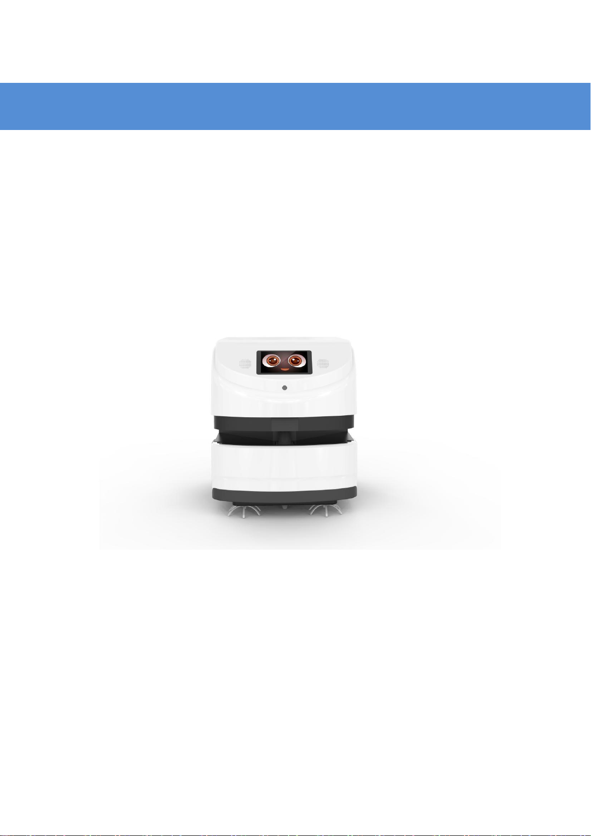
Introduction to Robots
Use environment requirements
Please use this product in accordance with the instructions of the manual.
Any loss caused by improper use shall be borne by the user.
Do not use in places with stairs or drops
There should not be a lot of black marble and black reflective cabinets at
the height of 27 cm
Do not travel on the ground with high friction: thicker and softer carpets
Do not use in a large amount of stagnant water and similar environments
There should be no densely placed thin-legged chairs in the travel area
Do not use in an environment above 50°C and below 0°C
Do not use on uneven and sloped roads
There are a lot of transparent glass and thin-legged tables and chairs,
which can be used depending on the construction of the map and the test
situation

2
Hardware parameters
Hardware parameters
Index performance
Product specification
Product Size
Length 684mm * Width 500mm * Height
600mm
product weight
80kg with packaging
Product color
white
product material
3D printed parts
Environmental
requirements
Storage temperature: -15°C~55°C; Working
temperature: 0°C ~ +50°C Humidity (RH):
10%~90%
Android specifications
operating system
Android 5.1
language support
Chinese
Processor type
RK3128
RAMLPDDDR3
1G
Built-inNAND FLASH
8GB
USB Debug port
Micro USBinterface
Display screen
7 inch, IPS screen (16:9) resolution 1024X600
External I/O port
1 USB 2.0 (MICROUSB), RJ45 network port
speaker
4Ω/3W Mono speaker

3
Wireless technology
AP6255
Support dual frequency 2.4&5G
WIFI 802.11b/g/n non-domain network cable
office
11ac 5.15GHz-5.825GHz
ROS Navigation specifications
operating system
LINUX
Lidar
Laser wavelength 905 nm, working area 270°
Single axis gyroscope
sensor
Yaw angle measurement
hard disk
32G high-speed solid state drive
motor driven
6.5 inch hub motor
Infrared sensor
Communicate with charging piles within 1
meter
512AN_HMW module Intel
WIFI
Support dual frequency 2.4&5G
WIFI&BT4.1 802.11b/g/n wireless LAN
11ac 5.15GHz-5.825GHz
Moving speed
Min 0.1 m/s, max0.5 m/s
Navigation board
Intel Core I5 motherboard
Remote function
Support remote navigation status monitoring,
remote online update navigation system
Light tube
UV lamp
16W

4
Water tank
Volume
15L
Power system
24V Rectifier
LPS-425-40A24U DC24V output power 48W
rectifier
Motor
Vacuum cleaner, solenoid water valve switch,
suction pump motor, roller motor
charging method
Automatic recharge, DC direct charge
adapter
enter:AC110-240V.50-60HZ
Output:DC43.2V-5A
Robot input power
42V--5A
battery
25AH lithium iron phosphate, 38.4V/960W
Charging pile parameters
Overcurrent protection, intelligent power off,
output rated voltage: 43.2VDC, output rated
current: 5A
Charging time
5.5-6 hour
Battery life
4-6 hour

5
Meet your robot
1. 7 inch display
2.3d camera
3. Lidar
4. Brush strip
5. Dust suction port
6. Driving wheel
7. Emergency stop switch
8. Infrared sensor
9. Automatic charging shrapnel
10. Absorbent sponge
11.Direct charging source hole
12. Ultrasound
13.Clean the sponge
14. Universal wheel
15. Trash box
16.Water tank
Cleaning precautions: ①Touch screen ③Laser navigation. Do not wipe
with a wet towel to avoid water ingress!
Precautions for use: ③Laser: Do not block the laser with objects
⑦Emergency stop switch: The emergency stop switch can only be rotated
to the right, do not rotate to the left

6
Use your robot
1. Boot
The power button is located on the base 11 on the back of the robot. It is a
button switch. Press it once to turn it on, and press and hold the power
button for 3 seconds to turn it off.
Note for shutdown: Press and hold the power button for 3 seconds, the
display will turn off the screen first, and then the motor will be powered off,
and finally the chassis light will go out!

7
2. Charging
Get to know your charger
The adapter plug needs to be plugged into the 110-220 V voltage, and the
DC head is plugged into the automatic charging pile. At this time, the green
light of the charging pile will be on, indicating that it is ready to charge.
Automatic charging: the robot can automatically detect the power and
charge automatically when the power is lower than the set threshold
(prerequisite: it is necessary to build a good map to mark the point of the
charging pile, the calibration method is as follows)

8
Direct charging: plug the power adapter cable into the power supply on the
back of the robot
Automatic charging hardware description
Placement of charging pile

9
Notes on the selection of charging pile location
3. Navigation
Note:The following content is an introduction to all the functions of the robot
deployment background. The functions that must be operated are as shown
in the points 1, 2, 3, 4 and 5 in the following figure. Other functions depend
on the specific scenarios and usage conditions.

10
The step 1 [Network Settings]
Note: The router network segment cannot be the 192.168.10.x network
segment
1. Open the [Settings]-[WLAN] on the Android screen of the robot to connect
to Wi-Fi
2. Open the Ftp application and enter the following interface. Follow the
steps shown in the figure. If the Wi-Fi password already exists, click "Send
Wi-Fi Information to Connect to ROS".

11
①Check the Wi-Fi name you want to connect to
②Enter Wi-Fi password
③Send Wi-Fi information to the navigation system (just click once, don't
click repeatedly)
④Show IP for connection success (show 127.0.0.1 for connection failure)
3. The scanning device should be connected to the same LAN as the machine.
Open the browser and input the IP address of the machine (Chrome browser
is recommended)
If the Wi-Fi connection fails, you can click ③again to reconnect. If it still fails,
you can connect to another network.

12
The step 2 [ Build mode ]
The purpose of building the map is to let the robot know the working
environment
The robot needs to scan the actual environment and construct an "original
map". During the navigation process, the robot can compare with the
original map based on the real-time scanning situation and find its own
position.
The viewing angle of the Lidar is 270°, and the scanning range is the
horizontal plane of the radar height; the scanning distance is 20 meters
Ask people to stand behind to push the robot, or use the keyboard arrow
keys to control the mapping

13
1,After entering the webpage, the default state is "Navigation Mode", click to
switch to "Mapping Mode" and select "Laser Mapping" to enter the state as
shown below to start scanning.

14
①Get IP from FTP software
②Switch to mapping mode and select "Laser Mapping"
2,After entering the "map mode", the machine first rotates in place to clean
the surrounding feature points, and the speed should not be too fast when
rotating, and the machine can be controlled to go after one rotation. In
narrow areas, you can walk straight. Pay attention to the gaps during walking.
Slowly rotate the machine 90°facing the gap to clean the feature points, and
then slowly turn back to continue scanning; open areas can follow the
U-shaped route, as follows:
3,When controlling the machine to go, pay attention to whether the laser
matches the actual terrain. If it does not match, stop and wait for a while, wait
until the laser matches the actual terrain before continuing. As shown below:

15
Figure 1: mismatch between laser and terrain (when the laser does not match
the terrain, stop and wait for the laser to match the terrain before pushing the
robot to build the map)
Figure 2: matching of laser and terrain (some areas need robot to turn to be
able to scan clearly, such as wide terrain and room)
4,Do not move the machine after the machine reaches the end point. Just
observe whether the map is clean, without ghosting and matches the actual
terrain. If there is no obvious dislocation, click "composition completed". If
there is any dislocation, please wait for a period of time, and the algorithm
will correct it.If the correction is not successful in 10 minutes, consider
rebuilding the map.

16
matters needing attention:
1. When pushing or controlling the robot, walk slowly and observe whether
the laser matches the terrain. If there is a mismatch, stop and wait for the
laser to match the current terrain.
2. After the robot reaches the destination, observe whether the map is clean
without ghosting and matches the actual terrain. If there is no obvious
dislocation, click "composition complete". If there is any dislocation, please
wait for a period of time, and the algorithm will correct it.If the correction is
not successful in 10 minutes, consider rebuilding the map.

17
Step 3 [ Edit clean area ]
Edit: Use polygons to draw the area that needs to be cleaned
Ranging: measuring distance
Clean area: Click to pop up all clean areas for editing
The step 4 [ Virtual wall ]
Edit the function of virtual wall: restrict the active area of robot

18
Drag: This mode can zoom, pan and rotate the map. In this mode, press
"ctrl+left mouse button" to select a rectangular area, and the virtual wall in
this area will be cleared
Draw a curve: often used to draw irregular terrain
Draw a straight line: connect two points to form a straight line, which is
often used for regular terrain or rough drawing of an area
Save: Only click save to save the drawn virtual wall
Clear: Clear all virtual walls (need to click save to take effect)
Example: glass wall
Note: the laser can penetrate the glass, so when drawing the virtual wall, pay
attention to the virtual wall outside the glass

19
figure 1 Actual environment figure 2 Map scanned by laser
figure 3 error figure 4 correct
Example: table
Note: the laser can only scan one horizontal plane, so when drawing the
virtual wall, consider the desktop projection
figure 1 Actual environment figure 2 Map scanned by laser
figure 3 error figure 4 correct
matters needing attention:
1. The minimum passing distance of the machine is 1.5m, so attention should
be paid when drawing the virtual wall
Table of contents