Sheet # 692/1u – Electric connectors (F610)
Version 1.04a User guide ATEQ 6th series Page 5/7
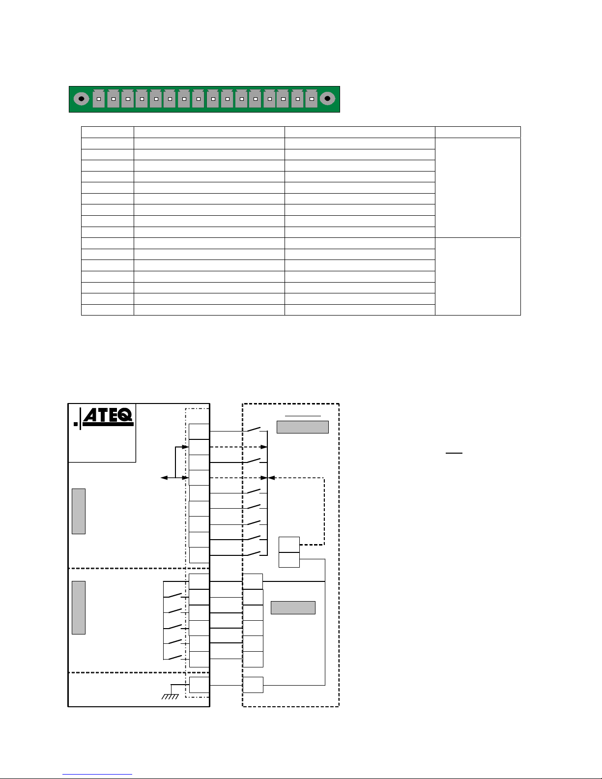
4.2. CONNECTOR I/O ALL OR NOTHING
1 2 3 4 5 6 7 8 9 10111213141516
Inputs / Outputs All or Nothing.
Pin Standard Mode Compact Mode
1 Input 1 RAZ Input 1 RAZ
2 Common (+ 24 V) Common (+ 24 V)
3 Input 2 START Input 2 START
4 Common (+ 24 V) Common (+ 24 V)
5 Input 3 Program selection Input 3 Program selection
6 Input 4 Program selection Input 4 Program selection
7 Input 5 Program selection Input 5 Program selection
8 Input 6 Program selection Input 6 Program selection
9 Input 7 Program selection Input 7 Program selection
Inputs
(Activation by
24 V DC)
Common
+ 24 V = 0,3 A
maximum
10 Floating common output Floating common output
11 Output 1 Pass part Output 1Pass part cycle 1
12 Output 2 Fail Test part Output 2 Fail part cycle 1 + Alarm
13 Output 3 Fail reference part Output 3 Pass part cycle 2
14 Output 4 Alarm Output 4 Fail part cycle 2 + Alarm
15 Output 5 End of cycle Output 5 End of cycle
16 0 V 0 V
Outputs dry
contacts
60V AC / DC Max
200mA Max
The compact mode is a software function which is activated in the CONFIGURATION/
AUTOMATISM / CHANGE I/O / OUTPUT menu.
4.2.1. Connector (I/O Inputs/Outputs) graphical representation
4.2.1. 1) PLC in NPN mode connection
I1(Reset)
Customer
Input boards
16/32 programs
I2(Start)
I3(Pr 1 + 1)
I4(Pr 2 + 1)
Good part
Common
Test fail part
Reference fail part
Alarm
End of cycle
24 V DC
24 V DC
ATEQ or customer
I6(Pr 8 + 1)
I5(Pr 4 + 1)
I7(Programmable input)
16
15
14
13
12
11
10
9
8
7
6
5
4
3
2
1
NPN MODE
Ground
+ 24 V DC
J3
INPUTSOUTPUTS
OUTPUTS
+
-
INPUTS
Customer
0 V
(0,3 A max)
Note: The 24V power supply must
be provided by the internal power
supply of the ATEQ instrument
(0,3A maximum) OR through an
external power supply provided by
the customer.
In the case of customer external
supply, the ATEQ instrument can
be supply by the 2 and 4 pins on
the J3 connector too.