NO
1
2
3
4
5
6
7
8
9
10
11
12
13
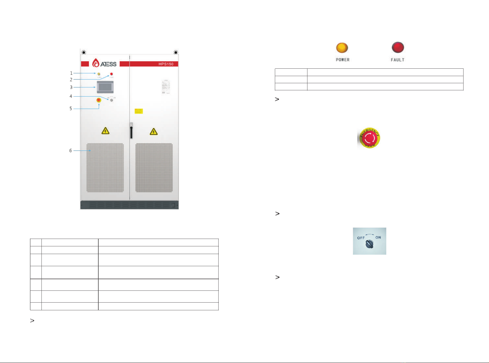
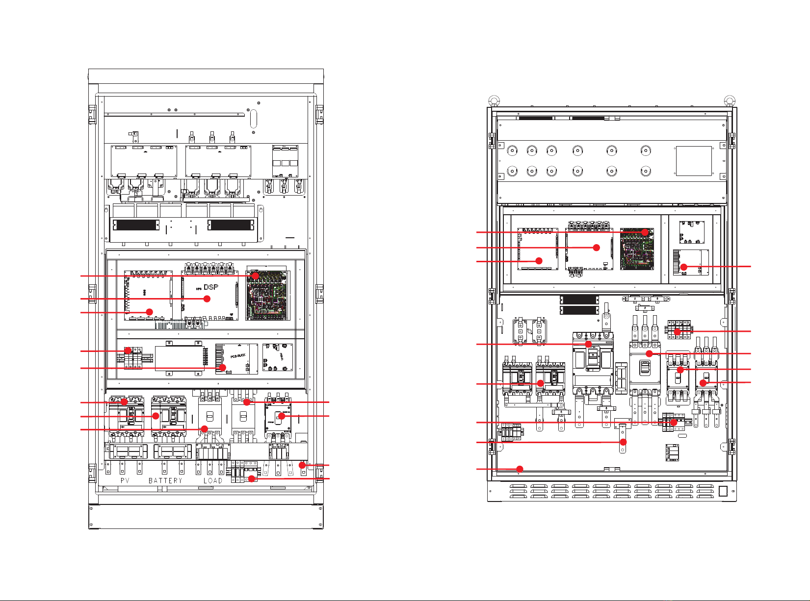
Name
PV input
Battery input
AC input
BYPASS
AC output
Power supply micro break*3
AC lightning protection switch
Interface board
Controal board
Sampling board
BUCK board
N terminals
Earth terminals
Description
Control the connection of battery and HPS
Control the connection of battery and HPS
Control the connection of grid and HPS
Maintenance switch, see 9.1.1 for details
Control the connection of load and HPS
power board, fan power switch
Switch for AC lightning protection
inverter power supply conversion PCB
inverter
interface
main control board, with communication
voltage current temperature sampling PCB
DC power supply PCB
Load and grid N terminals
Grounding bronze terminals
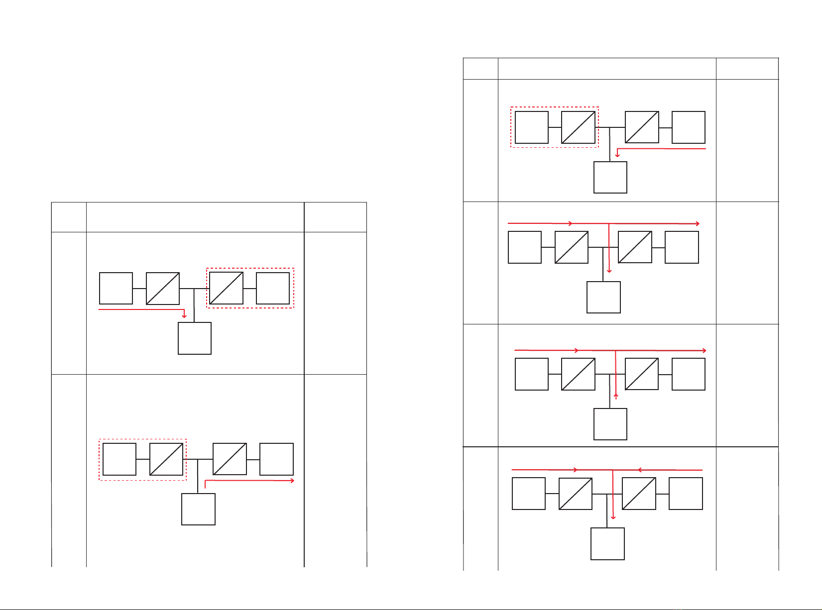
3.4 Operation mode and status
Please refer to Section for details on operation mode setup procedure.7.2.4
Caution!
Before the machine leaves the factory, the operation mode will be set according to the
technical agreement. ATESS will not be responsible for the consequences caused by
modifying the operation mode without the consent of ATESS. Please contact ATESS
personnel for modification if needed.
Anti-backflow
1.When anti-backflow enable is set to 1, feeding power to utility gird is restricted.
2.When anti-backflow enable is set to 0, HPS can feed power to utility grid.
enable
Optional functions in grid connection mode:
3.4.1 On grid mode
G charge together enable
1.When simultaneous charging function enable is set to 1, grid and PV can charge battery
simultaneously.
2.When simultaneous charging function enable is set to 0, grid and PV can not charge battery at
the same time.
Please refer to Section 7.2.4 for setup procedure.
rid&PV
3.4.1.1 Load first mode (anti-backflow function optional)
1. When PV energy is sufficient, PV supply priority to load, the remaining to battery.
2. When PV power is lower than load power, battery discharge automatically. if battery discharged cutoff
voltage or cut-off SOC (depending on battery type), it will stop discharging, PV and grid supply power to
the load together. The power supply can be restored when the battery is charged to the set value of
battery saturation.
See Chapter 7.2 for details of discharge cut-off voltage, SOC and BAT_charged_ saturation
3.4.1.2 Battery first mode (anti-backflow function optional)
1. When the PV energy is sufficient, PV supply priority to battery charge, the remaining to load;
2. When PV energy is insufficient, the PV charge the battery first. The power grid only supplies all loads
without charging the battery. It is optional to charge the battery at the same time (PV&grid charge
together enable, which is set to 1 by default when leaving factory);
3. If the grid connected backup mode is not discharged or switched to other modes, To maintain
electrochemical activity, the battery will enter the discharge state after one week of current limiting
charging, and the discharge power will be calculated according to battery specifications.
3.4.1.3 Time shifting mode(anti-backflow function optional)
The period of economic mode is divided into peak period, fair period and valley period. Please refer to
section 7.2.4 for the setting details.
1. Valley price: working logic is the same to the backup priority mode’s.
2. Fair price:
A. Battery can neither discharge nor be charged by grid.
B. PV power supply priority to load, the remaining to battery when PV power is higher than load.
C. When PV power is lower than load power, PV and grid supply load, PV doesn’t charge battery.
3. Peak price:
A. Grid will not charge battery.
B. When PV power is higher than load, PV supplies to load , the remaining to
battery.
C. When PV power is lower than load power, there are two conditions:
(1) When battery voltage is higher than the discharge cut-off voltage or the discharge cut-off SOC
(depending on the battery type), PV and battery supply the load.
(2) When battery voltage is less than or equal to the discharge cut-off voltage or the discharge cut-off
SOC (depending on the battery type), the battery does not discharge, and the PV and the grid jointly
supply the load and do not charge the battery.
3.4.1.4 Peak-shaving(Grid)
Note: in this mode, the upper limit power of power grid should be set. This value only limits the power
taken from grid, not the power fed to grid.
1. When PV power is greater than the load and charging power, do not take power from the grid, PV
supplies load and charge the battery;
2. (When PV power + upper limit power of grid) is greater than (load power + charging power), grid and
PV supply load and charge battery at the same time.
3. When (PV power + upper limit power of power grid) is greater than the load power, grid and PV supply
priority to the load and the remaining charge batteries.
4. When (PV power + grid upper limit power) is less than the load power, the grid, PV and battery supply
the load at the same time.
9 10