ATI Technologies VersaFinish 9150-ACT-390-0-0-0 User manual

Engineered Products for Robotic Productivity
Pinnacle Park • 1031 Goodworth Drive • Apex, NC 27539 • Tel: +1.919.772.0115 • Fax: +1.919.772.8259 • www.ati‑ia.com • Email: info@ati‑ia.com
VersaFinish™
Axially Compliant Robotic Finishing Tool
(Model 9150‑ACT‑390‑0‑0‑0 and 9150‑ACT‑390‑NL)
Product Manual
Document #: 9610-50-1012

Manual, VersaFinish, ACT‑390 Series
Document #9610‑50‑1012‑18
Pinnacle Park • 1031 Goodworth Drive • Apex, NC 27539 • Tel: +1.919.772.0115 • Fax: +1.919.772.8259 • www.ati‑ia.com • Email: info@ati‑ia.com
2
Foreword
CAUTION: This manual describes the function, application, and safety considerations of this
product. This manual must be read and understood before any attempt is made to install or
operate the product, otherwise damage to the product or unsafe conditions may occur.
Information contained in this document is the property of ATI Industrial Automation, Inc (ATI) and shall not be
reproduced in whole or in part without prior written approval of ATI. The information herein is subject to change without
notice. This manual is periodically revised to reect and incorporate changes made to the product.
The information contained herein is condential and reserved exclusively for the customers and authorized agents of ATI
Industrial Automation and may not be divulged to any third party without prior written consent from ATI. No warranty
including implied warranties is made with regard to accuracy of this document or tness of this device for a particular
application. ATI Industrial Automation shall not be liable for any errors contained in this document or for any incidental
or consequential damages caused thereby. ATI Industrial Automation also reserves the right to make changes to this
manual at any time without prior notice.
ATI assumes no responsibility for any errors or omissions in this document. Users’ critical evaluation of this document is
welcomed.
Copyright by ATI Industrial Automation. All rights reserved.
How to Reach Us
Sale, Service and Information about ATI products:
ATI Industrial Automation
1031 Goodworth Drive
Apex, NC 27539 USA
www.ati‑ia.com
Tel: +1.919.772.0115
Fax: +1.919.772.8259
E‑mail: info@ati‑ia.com
Technical support and questions:
Application Engineering
Tel: +1.919.772.0115, Option 2, Option 2
Fax: +1.919.772.8259
E‑mail: mech_support@ati‑ia.com

Manual, VersaFinish, ACT‑390 Series
Document #9610‑50‑1012‑18
Pinnacle Park • 1031 Goodworth Drive • Apex, NC 27539 • Tel: +1.919.772.0115 • Fax: +1.919.772.8259 • www.ati‑ia.com • Email: info@ati‑ia.com
3
Glossary
Term Denition
ACT Axially Compliant Finishing Tool.
Adapter Device for attaching the tool to robots or work surfaces.
Air Filter Device for removing contamination from air supply lines. Typically refers to removal of
particulates.
Air Lubricator Device for adding controlled volumes of lubricating oil to the air supplying the air motor.
Bur Cutting tool that is used to remove burrs from the workpiece.
Burr Any unwanted, raised protrusion on the workpiece.
Chuck Gripping device used to hold tools and media to the spindle.
Coalescing Filter Device that removes liquid aerosols from the supply air lines.
Compliance The ability of the spindle to passively move in response to protrusions on or deviations
of the work piece.
Forward Sensor The forward sensor is an inductive proximity switch which is ON when the spindle is in
the fully forward position indicating there is no contact with the tool.
Gearhead A gearbox responsible for reducing the spindle speed of the air motor.
Main Housing The main cylindrical body of the unit which includes the mounting features.
Media Term referring to tools and/or abrasives held by the tool during the completion of a
manufacturing process.
Qty Quantity
Rear Housing Rear cover to the main housing. This body includes a connection port for the compliance
air supply and feed‑through seals for optional electrical sensors.
Regulator Device used to set and control the supplied air pressure to lower acceptable levels.
Retract Sensor The retract sensor is an optional inductive proximity switch which is ON when the
spindle is in the fully back position indicating there is no further motion possible.
Solenoid Valve Electrically controlled device for switching air supplies on and o.
Spindle The rotating portion of the tool assembly.
Tachometer
Sensor
(Applicable to legacy models only). The tachometer sensor is an optional inductive
proximity switch which monitors the rotation of a disk mounted behind the chuck on the
spindle. The sensor will deliver two OFF pulses per spindle rotation. It is recommended
that the tachometer sensor be utilized for process development but removed from the
unit when in a production environment.
Vane Motor Air motor that drives the tool spindle.
VersaFiniah An ATI series of deburring tools that use a vane‑type motor with an axially oating
spindle. The deburring tool is for material nishing operations.

Manual, VersaFinish, ACT‑390 Series
Document #9610‑50‑1012‑18
Pinnacle Park • 1031 Goodworth Drive • Apex, NC 27539 • Tel: +1.919.772.0115 • Fax: +1.919.772.8259 • www.ati‑ia.com • Email: info@ati‑ia.com
4
Table of Contents
Foreword .......................................................................................................................................... 2
Glossary ........................................................................................................................................... 3
1. Safety......................................................................................................................................... 6
1.1 ExplanationofNotications......................................................................................................... 6
1.2 General Safety Guidelines............................................................................................................ 6
1.3 Safety Precautions ........................................................................................................................ 7
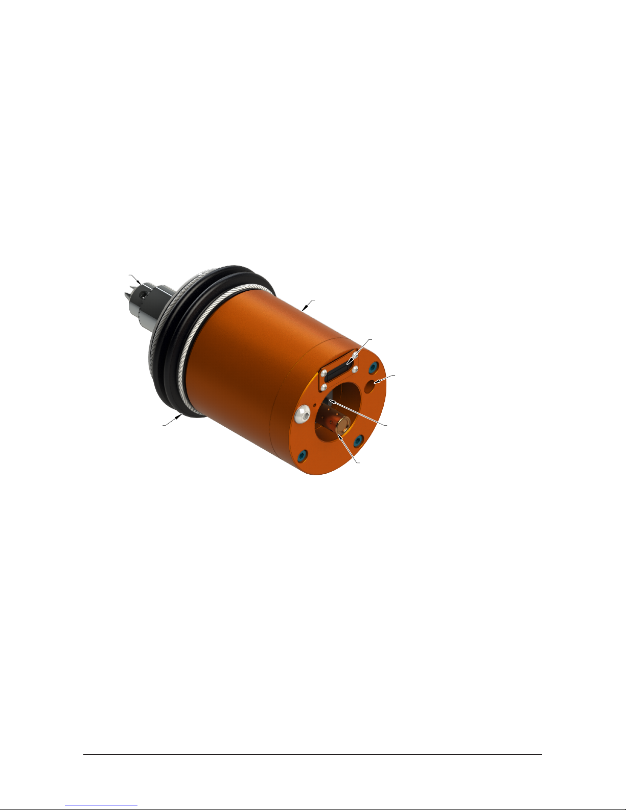
2. Product Overview..................................................................................................................... 8
2.1 FeaturesandBenetsoftheVersaFinishDeburringTool ........................................................ 8
2.2 VersaFinish Part Numbering Legend .......................................................................................... 9
2.3 Technical Description ................................................................................................................ 10
2.3.1 Environmental Limitations ................................................................................................ 10
2.3.1.1 Operation .......................................................................................................... 10
2.3.1.2 Storage ............................................................................................................. 10
2.4 Compliance Unit Performance ................................................................................................... 11
3. Installation .............................................................................................................................. 13
3.1 Protection During Transportation.............................................................................................. 13
3.2 Inspection of Condition When Delivered .................................................................................. 13
3.3 Unpacking and Handling ............................................................................................................ 13
3.4 Storage and Preventive Maintenance During Storage............................................................. 13
3.5 Side Mounting Installation ......................................................................................................... 14
3.6 Pneumatic Connections ............................................................................................................. 15
4. Operation ................................................................................................................................ 17
4.1 Safety Precautions ...................................................................................................................... 17
4.2 Normal Operation ........................................................................................................................ 18
4.2.1 Air Quality......................................................................................................................... 18
4.2.2 Lubrication........................................................................................................................ 18
4.2.3 Media Selection................................................................................................................ 18
4.2.4 Deburring Tool Approach Path Should Be Slow and At an Angle..................................... 19
4.2.5 No Radial Loads............................................................................................................... 19
4.2.6 Program the Robot to Incorporate 50% Compliance Travel of the Tool ........................... 19
4.3 VersaFinish Working Environment............................................................................................ 19
4.4 Sensor Connections ................................................................................................................... 20
4.5 Tool Position and Programming ................................................................................................ 21

Manual, VersaFinish, ACT‑390 Series
Document #9610‑50‑1012‑18
Pinnacle Park • 1031 Goodworth Drive • Apex, NC 27539 • Tel: +1.919.772.0115 • Fax: +1.919.772.8259 • www.ati‑ia.com • Email: info@ati‑ia.com
5
5. Maintenance............................................................................................................................ 22
5.1 Routine Operational Maintenance ............................................................................................. 22
5.2 Media Replacement..................................................................................................................... 22
5.3 Utilities ......................................................................................................................................... 22
5.4 Lubrication................................................................................................................................... 22
6. Troubleshooting and Service Procedures ........................................................................... 23
6.1 Troubleshooting .......................................................................................................................... 23
6.2 Service Procedures..................................................................................................................... 24
6.2.1 Media Selection................................................................................................................ 24
6.2.2 Flexible Boot Replacement .............................................................................................. 24
6.2.3 Air Motor Muer Replacement......................................................................................... 25
6.2.4 Air Motor Replacement..................................................................................................... 26
6.2.5 Sensor Replacement........................................................................................................ 29
6.2.5.1 Forward Sensor (Option ‑F).............................................................................. 29
6.2.5.2 Retract Sensor (Option ‑R) ............................................................................... 32
6.2.5.3 Tachometer Sensor (Option ‑T) ........................................................................ 34
7. Serviceable Parts ................................................................................................................... 38
7.1 Accessories, Tools, and Optional Replacement Parts ............................................................ 38
8. Specications ......................................................................................................................... 39
9. Drawings ................................................................................................................................. 40
10. Terms and Conditions of Sale............................................................................................... 43
10.1 Motor Life and Service Interval Statement................................................................................ 44
10.1.1 Vane Motor Products (VersaFinish).................................................................................. 44

Manual, VersaFinish, ACT‑390 Series
Document #9610‑50‑1012‑18
Pinnacle Park • 1031 Goodworth Drive • Apex, NC 27539 • Tel: +1.919.772.0115 • Fax: +1.919.772.8259 • www.ati‑ia.com • Email: info@ati‑ia.com
6
1. Safety
The safety section describes general safety guidelines to be followed with this product, explanations of the
notications found in this manual, and safety precautions that apply to the product. More specic notications are
imbedded within the sections of the manual where they apply.
1.1 ExplanationofNotications
The following notications are specic to the product(s) covered by this manual. It is expected that the user
heed all notications from the robot manufacturer and/or the manufacturers of other components used in the
installation.
DANGER: Notication of information or instructions that if not followed will result in
death or serious injury. The notication provides information about the nature of the
hazardous situation, the consequences of not avoiding the hazard, and the method for
avoiding the situation.
WARNING: Notication of information or instructions that if not followed could result
in death or serious injury. The notication provides information about the nature of the
hazardous situation, the consequences of not avoiding the hazard, and the method for
avoiding the situation.
CAUTION: Notication of information or instructions that if not followed could result
in moderate injury or will cause damage to equipment. The notication provides
information about the nature of the hazardous situation, the consequences of not
avoiding the hazard, and the method for avoiding the situation.
NOTICE: Notication of specic information or instructions about maintaining, operating,
installing, or setting up the product that if not followed could result in damage to equipment. The
notication can emphasize, but is not limited to: specic grease types, best operating practices,
and maintenance tips.
1.2 General Safety Guidelines
Prior to purchase, installation, and operation of the ATI product, the customer should rst read and
understand the operating procedures and information described in this manual. Follow installation
instructions and pneumatic connections as described in this manual.
All pneumatic ttings, tubing, cables, and cable ttings must be capable of withstanding the repetitive
motions of the application without failing. The routing of utility lines must minimize the possibility of
stress/strain, kinking, rupture, etc. Failure of critical pneumatic lines to function properly may result in
equipment damage.

Manual, VersaFinish, ACT‑390 Series
Document #9610‑50‑1012‑18
Pinnacle Park • 1031 Goodworth Drive • Apex, NC 27539 • Tel: +1.919.772.0115 • Fax: +1.919.772.8259 • www.ati‑ia.com • Email: info@ati‑ia.com
7
1.3 Safety Precautions
CAUTION: Do not use spare parts other than original ATI spare parts. Use of spare
parts not supplied by ATI can damage equipment and void the warranty. Always use
original ATI spare parts.
CAUTION: Never be present near the deburring tool while it is started or in operation.
Flying debris and rotating parts can cause injury. If it is necessary to approach the
deburring tool while in motion, stand behind appropriate Plexiglas®or Lexan®windows.
Provide a barrier to prohibit people from approaching the deburring tool while in
operation must secure the installation.
CAUTION: Do not perform maintenance or repair on the VersFinish product unless the
tool is safely supported or placed in the tool stand and air has been turned o. Injury
or equipment damage can occur with tool not placed in a tool stand and air remaining
on. Place the tool safely in the tool stand and turn o the air before performing
maintenance or repair on the VersaFinish product.

Manual, VersaFinish, ACT‑390 Series
Document #9610‑50‑1012‑18
Pinnacle Park • 1031 Goodworth Drive • Apex, NC 27539 • Tel: +1.919.772.0115 • Fax: +1.919.772.8259 • www.ati‑ia.com • Email: info@ati‑ia.com
8
2. Product Overview
ATI's Axially‑Compliant Finishing Tool, also known as VersaFinish, is a robust, low‑speed, high‑torque air tool
with an axially oating spindle, suitable for a multitude of robotic and non‑robotic material nishing operations on
aluminum, plastic, steel, etc.
The rotating spindle is equipped with a 3/8” chuck for holding customer‑supplied tools. These may include, but
are not limited to, abrasive brushes, wire brushes, sanding disks, polishing points, and chamfering tools. While
spinning at low speeds the customer's tool is pushed against the workpiece using an adjustable air supply to control
the contact force. This constant pneumatic force allows the spindle to respond axially to changes in part prole.
The force control system provides very high stiness in the path direction and a low stiness in the contact force
direction.
Optional sensing devices are available to detect the position of the spindle and monitor its speed for process
development. The oating head design reacts quickly to any variances in part position or robot path.
Figure 2.1—Product Overview
Air Motor Supply Port
Air Motor Exhaust Muffler
Compliance Force Air Supply Port
Tool Chuck
Dust Boot
Cable Access for Optional Sensors
Compliance Housing
2.1 FeaturesandBenetsoftheVersaFinishDeburringTool
• Reliable vane motor
A robust vane‑type air motor with gear reduction and rugged components that provides a long
service with exceptional power.
• High‑torque performance
Vane motors increase their torque in response to loads that are introduced in nishing operations.
• Floating axial compliance
Remotely‑adjusted air pressure controls and maintains the constant axial force on the oating
spindle. The axially‑compliant motion of the spindle allows the customer's tool to compensate for
deviations in the part prole along the robot path, compensate for tool wear, and provide constant
contact force with the workpiece.
• Mounting options
The VersaFinish is provided with a mounting pattern on the side of its housing. Adapter plates may
easily be customized for robotic, bench, or xture mounting

Manual, VersaFinish, ACT‑390 Series
Document #9610‑50‑1012‑18
Pinnacle Park • 1031 Goodworth Drive • Apex, NC 27539 • Tel: +1.919.772.0115 • Fax: +1.919.772.8259 • www.ati‑ia.com • Email: info@ati‑ia.com
9
• Simple Tool Holder
The VersaFinish is supplied with a simple key‑actuated 3/8”chuck for holding common
media. The spindle is threaded to allow replacement of the chuck with customer‑supplied or
custom‑manufactured media holders. The VershFinish motor has an industry standard 3/8‑24
right‑hand spindle thread. The supplied drill chuck can be removed to attach any number of chucks,
collets or custom tooling.
• Easy programming of the robot
The axial motion of the spindle allows fast and simple programming of the robot. This movement
also compensates for changes in part tolerances, part misalignment, tool wear, and robot path
variation.
• Optional Sensors
To assist in process development or monitoring, the VersaFinish may be ordered with optional
sensors to detect the spindle speed and forward or retracted positions (3) options are available:
F = Forward Sensor (spindle pushed fully extended)
R = Retract Sensor (spindle pushed fully retracted)
T = Tachometer Sensor (rotational speed of the spindle)
• Dust boot
The tool is equipped with a simple boot between the moving motor mounting plate and the main
housing. This boot is provided to minimize contamination of the guide and piston rods that allow
free axial motion. This boot is not provided as a safety device. Under no circumstances should the
user operate the unit without the boot. The user should never have their hands on or near the unit
when in operation.
2.2 VersaFinish Part Numbering Legend
Figure 2.2—Part Numbering Legend

Manual, VersaFinish, ACT‑390 Series
Document #9610‑50‑1012‑18
Pinnacle Park • 1031 Goodworth Drive • Apex, NC 27539 • Tel: +1.919.772.0115 • Fax: +1.919.772.8259 • www.ati‑ia.com • Email: info@ati‑ia.com
10
2.3 Technical Description
A technical overview of the product is provided in the following tables and graphs. For additional technical
specications, refer to Section8—Specications.
2.3.1 Environmental Limitations
2.3.1.1 Operation
Table 2.1—Operation
Installation
position.
Mounted to machining center by means various,
customer‑supplied tool holders/adapters.
Temperature
range
5° C–35° C
41° F–95° F
Utilities
The tool requires the following:
• Clean, dry, ltered, and lubricated air (refer to
Section 4.2.2—Lubrication).
• A coalescing lter and lter elements that are rated 5
micron or better.
• The 960 W air motor consumes air at a rate of 19 CFM
(9 l/s) at 6.2 bar (90 psi)
• The axial force/compliance air must be supplied at
0.34 ‑ 4.1 bar (5‑60 psi) from a regulated source.
2.3.1.2 Storage
Table 2.2—Storage
Temperature
range
0° C–45° C
32° F–113° F
Conditions
The tool should be stored in its crate and in a dry place.
When not in use, keep the unit in its crate if possible.
Consult Section 3.4—Storage and Preventive
Maintenance During Storage of this manual.

Manual, VersaFinish, ACT‑390 Series
Document #9610‑50‑1012‑18
Pinnacle Park • 1031 Goodworth Drive • Apex, NC 27539 • Tel: +1.919.772.0115 • Fax: +1.919.772.8259 • www.ati‑ia.com • Email: info@ati‑ia.com
11
2.4 Compliance Unit Performance
The friction created by the mass of the customer supplied motor resting on the horizontally mounted stage
varies from tool to tool which makes compliance force variable. The compliance force varies linearly with
air pressure using the basic formulas shown in the chart below. Measurements may vary from one product to
another, and should only be treated as nominal.
Figure 2.3—Horizontal Compliance Force Curves
0.34 1.09 1.84 2.59 3.34 4.09
14
27
40
53
66
3
6
9
12
15
5 15 25 35 45 55
Air Pressure (bar)
Compliance
Force (N)
Compliance
Force (lbs)
Air Pressure (psi)
The force characteristics shown are for horizontal, rigidly‑mounted installations. The weight of the motor,
customer supplied chuck, and abrasive media must be added to this if the motor is mounted vertically with
the spindle down or subtracted with the spindle pointed up. Units mounted at angles between horizontal
and vertical provide a compliance force that must be calculated based on the specic mounting geometry or
orientation.

Manual, VersaFinish, ACT‑390 Series
Document #9610‑50‑1012‑18
Pinnacle Park • 1031 Goodworth Drive • Apex, NC 27539 • Tel: +1.919.772.0115 • Fax: +1.919.772.8259 • www.ati‑ia.com • Email: info@ati‑ia.com
12
The air motor operating speed will change according to load applied to it developing the power required for
the specic task being attempted. The idle speed of the motor will be its maximum as no load is applied.
This will drop to a lower operating speed where it will develop the maximum torque. If the torque required
exceeds the maximum available, the motor will stall.
Figure 2.4—Motor Torque Curves
0.0
0.7
1.4
2.0
2.7
3.4
0
0.5
1
1.5
2
2.5
0 1000 2000 3000 4000 5000 6000
Torque (Nm)Torque (lb ‑ft)
RPM
Figure 2.5—Motor Power Curves
0.0
0.07
0.15
0.2
0.3
0.4
0.5
0
0.1
0.2
0.3
0.4
0.5
0.6
0 1000 2000 3000 4000 5000 6000
Power (kW)Power (hp)
RPM

Manual, VersaFinish, ACT‑390 Series
Document #9610‑50‑1012‑18
Pinnacle Park • 1031 Goodworth Drive • Apex, NC 27539 • Tel: +1.919.772.0115 • Fax: +1.919.772.8259 • www.ati‑ia.com • Email: info@ati‑ia.com
13
3. Installation
The compliance housing incorporates a side mounting pattern which can be used directly or through the use of an
optional bench mount adapter kit. See Section9—Drawings.
The tool must be rigidly mounted prior to use. Under no circumstances should the unit be used for manual/hand
operations. Once securely mounted, the unit should be supplied with clean, lubricated air ltered (5) micron or
better. The use of a coalescing lter is recommended to remove trace moisture from the air supply. Air line ttings
supplying the VersaFinish should be installed with care using a minimum of tape or liquid sealant. To prevent
contaminant damage to the air motor, all air lines should be blown down to remove debris prior to connection of the
VersaFinish.
3.1 Protection During Transportation
The VersaFinish tool arrives in packaging that secures and protects the tool during transportation. Always
use this packaging when transporting the VersaFinish in order to minimize the risk of damage.
3.2 Inspection of Condition When Delivered
Upon receipt, the following should be checked:
• Delivery in accordance with freight documents
• Packaging is in good condition.
If there is damage to any of the packaging, or if any of the goods have been exposed to abnormal handling,
unpack those parts that may have been damaged for a closer inspection. Contact ATI for assistance.
3.3 Unpacking and Handling
The VersaFinish should always be placed inside the accompanying packaging, while transportation, storing,
and handling.
3.4 Storage and Preventive Maintenance During Storage
For short‑term storage, the tool should be stored in its accompanying packaging and in a dry place.
For long‑term storage, the VersaFinish should be thoroughly cleaned of any burrs, dust, or debris. To protect
the air motor, the user may wish to inject several drops of oil directly into the motor input followed by a
short burst of supply air to insure the vanes and internal components are completely lubricated. The units
should not be disassembled. Place the tool inside a sealed, plastic bag and place the bagged tool inside the
crate.

Manual, VersaFinish, ACT‑390 Series
Document #9610‑50‑1012‑18
Pinnacle Park • 1031 Goodworth Drive • Apex, NC 27539 • Tel: +1.919.772.0115 • Fax: +1.919.772.8259 • www.ati‑ia.com • Email: info@ati‑ia.com
14
3.5 Side Mounting Installation
CAUTION: Thread locker applied to fasteners must not be used more than once.
Fasteners might become loose and cause equipment damage. Always apply new
thread locker when reusing fasteners.
CAUTION: The length of the fasteners should not interfere with the compliant motion of
the motor spindle. Refer to Section 9—Drawings for the maximum fastener length. Do
not use fasteners that exceed the maximum length; otherwise, damage will occur.
The side mounting pattern of the ACT nishing tool consists of (2) dowel pin holes and a number of
threaded holes as shown in Figure3.1. If the ACT nishing tool is permanently mounted to a work surface,
the robot carries the part to be nished to the nishing tool.
Figure 3.1—Side Mounting
(4) M6 Socket Head Cap Screw
(4) M5 Socket Head Cap Screw
(4) M5 Internal Tooth Washer
Mounting Bracket
Finishing Tool
(2) Dowel Pin

Manual, VersaFinish, ACT‑390 Series
Document #9610‑50‑1012‑18
Pinnacle Park • 1031 Goodworth Drive • Apex, NC 27539 • Tel: +1.919.772.0115 • Fax: +1.919.772.8259 • www.ati‑ia.com • Email: info@ati‑ia.com
15
3.6 Pneumatic Connections
Connect the VersaFinish tool as shown in Figure3.2.
Figure 3.2—Pneumatic Connections
WARNING: All pneumatic ttings and tubing must be capable of withstanding the
repetitive motions of the application without failing. The routing of pneumatic lines must
minimize the possibility of over stressing, pullout, or kinking the lines. Failure to do
so can cause some critical pneumatic lines not to function properly and may result in
damage to the equipment.
NOTICE: It is recommended that the customer use a coalescing lter and lter elements rated 5
micron or better to remove trace moisture. Water damage of the air motor or damage associated
with debris in the air lines is not covered under warranty. .
Conventional, customer‑supplied, pneumatic components are used to control the air supply to the tool. ATI
recommends that the user install a high‑ow pneumatic pressure regulator and a high‑ow valve to properly
supply a stable air supply of 90 psi (6.2 bar) to the spindle motor (ATI Part # 9150‑FRL‑3 or equivalent,
see Section2.4—ComplianceUnitPerformance for the maximum ow requirements.) While the spindle
motor can be operated below 90 psi (6.2 bar), it will not develop full power or speed. A second, precision,
self‑relieving regulator (ATI Part # 9150‑P16‑B‑G ) will supply air for the compliance or centering force.
Very little airow is required for the compliance mechanism.
The compliance force is applied axially and is adjusted until the desired nishing result is achieved.

Manual, VersaFinish, ACT‑390 Series
Document #9610‑50‑1012‑18
Pinnacle Park • 1031 Goodworth Drive • Apex, NC 27539 • Tel: +1.919.772.0115 • Fax: +1.919.772.8259 • www.ati‑ia.com • Email: info@ati‑ia.com
16
CAUTION: Pneumatic components used for the motor drive circuit must be capable
of meeting the air consumption requirements (See Section8—Specications). Poor
performance will result if the correct components are not used. Lubricators must be
located as close to the unit as possible with performance rapidly deteriorating when the
distance exceeds 15 feet (5 meters).
Table 3.1—Pneumatic Connections
Function Connection Type Pressure
Motor Inlet 1/4 NPT 6.2 bar
(90 psi)
Compliance (Axial) Force Inlet 1/8 NPT
0.34–4.1 bar
(5–60 psi)
(Maximum)
Exhaust 1/4 NPT Not Applicable
The tool must be plumbed using exible tubing. The inside diameter of the tubing should be as large as
practical to minimize pressure drop to the spindle motor [3/8" (10 mm) minimum].
The air motor is quiet and vents air to the environment through the supplied high‑ow muer at the rear
of the unit. The customer may choose to replace the muer with tubing to carry exhaust away from the
work area. Such tubing must have a minimum 1/2" (12.7 mm) inner diameter to minimize pressure drops
and allow unrestricted axial motion respectively. To reduce the sound level in neighboring working areas, a
customer‑supplied barrier surrounding the installation may be installed (Plexiglas or Lexan is preferred).
The compliance force air supply pressure regulator should be adjusted between 0.34–4.1 bar (5‑60 psi).
When testing for the proper contact force, start with a very low pressure and increase slowly until the
desired process result is achieved.

Manual, VersaFinish, ACT‑390 Series
Document #9610‑50‑1012‑18
Pinnacle Park • 1031 Goodworth Drive • Apex, NC 27539 • Tel: +1.919.772.0115 • Fax: +1.919.772.8259 • www.ati‑ia.com • Email: info@ati‑ia.com
17
4. Operation
These operating instructions are intended to help system integrators program, start up, and complete a robotic
cell containing a nishing tool. The system integrator should be familiar with the task of nishing in general, and
should have extensive knowledge relating to robots and automation incorporating robots.
4.1 Safety Precautions
DANGER: Never use the VersaFinish for purposes other than automated processes.
Never use the VersaFinish as a hand‑held machine.
DANGER: Never use the VersaFinish in a manner to produce radial loads. If a failure
occurs due to forces caused by improper use, hazardous situations for both personnel
and equipment could be created. Avoid using the VersaFinish for countersinking or
drilling. Rigid tools, such as milling machines, are required for such applications. The
use of radial media (wheel brushes and sanding drums) in the unit is discouraged as
this will lead to binding in the linear slides preventing axial motion.
WARNING: All personnel, who are involved in the operation of the VersaFinish product,
should have a thorough understanding of the operating procedures. Failure to follow
these procedures or neglecting safety precautions can create hazardous situations that
may injure personnel or damage the deburring installation and the VersaFinish product.
WARNING: Never operate the ATI product without wearing hearing protection. High
sound levels can occur during cutting. Failure to wear hearing protect can cause
hearing impairment. Always use hearing protection while working in the proximity of the
nishing tool.
WARNING: Never operate the ATI product without wearing eye protection. Flying
debris can cause injury. Always use eye protection while working in the proximity of the
nishing tool.
CAUTION: Do not use spare parts other than original ATI spare parts. Use of spare
parts not supplied by ATI can damage equipment and void the warranty. Always use
original ATI spare parts.
CAUTION: The compliance piston rods and (1) of the (2) oating guide rods that oat
in the front plate must not be restrained, for example: adding washers or additional
thread locker. Rigid mounting of the rods attached to the front plate will prevent oating
and result in binding of the unit’s axial compliance. The compliance piston rods and
the (1) guide rod oat in the front plate to allow the motor assembly to achieve free
compliant motion while resisting the motor's torque. Do not restrain the compliance
piston rods and (1) of the (2) oating guide rods.

Manual, VersaFinish, ACT‑390 Series
Document #9610‑50‑1012‑18
Pinnacle Park • 1031 Goodworth Drive • Apex, NC 27539 • Tel: +1.919.772.0115 • Fax: +1.919.772.8259 • www.ati‑ia.com • Email: info@ati‑ia.com
18
4.2 Normal Operation
The following sections describes the normal operating conditions for VersaFinish deburring tools.
4.2.1 Air Quality
The air supply should be clean, dry, ltered, and lubricated. A coalescing lter that has elements
rated for 5 micron or better is required. The air must be supplied at 6.2 bar (90 psi).
Air quality aects tool performance more than almost any other factor. Particulate can block
airow or impede vane motion. If deburring tools do not receive the proper air pressure, the tool
stalls.
4.2.2 Lubrication
Lubricate the air supply with 3‑5 drops of an oil‑fog lubrication mixture.
Vane motors for the ACT‑390 deburring tool should be run with lubrication in the air supply to
maximize motor life. If no lubrication is available, the motor can operate, but the life of the motor
is cut in half.
It is imperative that the lubricator be located within 5 m (15 feet) of the tool.
4.2.3 Media Selection
Use cup and encapsulated brushes that are under 3 inches in diameter.
Do not use media that requires radial loading. Do not use media rated to below the ACT‑390 speed.
Refer to Section8—Specications.
The ACT‑390 deburring tool is designed to use radially loaded media under 3 inches in diameter
due to its lower speed, and thus, sanding disks and cup brushes may be used. Plunge cuts for
countersinking are acceptable as long as the bur angle is 90° or larger so that there is minimal radial
load.
The VersaFinish air motor is equipped with an integral speed reduction gearbox. The life of this
gearbox is reduced if the media extends a long distance from the tip of the spindle. Whenever
possible, select media and mounting adapters for media that are short and position the work as
close to the VersaFinish as possible.
Select media and media holders that position the work piece as close to the VersaFinish as possible.
The selection of such media is highly dependent upon the work piece material and geometry,
and the amount of material to be removed. It is not practical to present all the possibilities in this
document.
In most applications, no cooling or lubrication of the part or tool is necessary nor is it desirable.
For some materials and situations, the addition of coolants or compressed air may aid the cutting
process. Any application of coolant must be exercised with care to prevent uids from entering the
tool or its chuck.
When used with exible abrasive media, the VersaFinish will perform best when the rotating
media approaches the burr in a direction that will fold the burr back on itself. This will allow the
media to remove material rapidly without excessive force and without the creation of a secondary
bur. This will decrease the cycle time for the operation while extending the life of the tool and the
consumable media. The VersaFinish spindle rotates clockwise when viewed from behind.

Manual, VersaFinish, ACT‑390 Series
Document #9610‑50‑1012‑18
Pinnacle Park • 1031 Goodworth Drive • Apex, NC 27539 • Tel: +1.919.772.0115 • Fax: +1.919.772.8259 • www.ati‑ia.com • Email: info@ati‑ia.com
19
4.2.4 Deburring Tool Approach Path Should Be Slow and At an Angle
The deburring tool should approach the workpiece slowly and at an angle.
When beginning a deburring pass, try to minimize the initial impact on the work piece by slowly
approaching the tool at an angle while maintaining a slightly parallel path with the surface.
If the tool quickly approaches perpendicularly to the workpiece, the result is gouging and
premature wear of the tool bearings and results in premature failing of the unit. Additionally,
collisions could result and create a hazardous situation for both personnel and equipment.
4.2.5 No Radial Loads
Do not apply radial loads, which are perpendicular to the axis of rotation.
4.2.6 Program the Robot to Incorporate 50% Compliance Travel of the Tool
Program the robot to have the tool's compliance at 50% travel when on the nominal path.
As the part's edge deviates from the perfect path, the cutting bit can use compliance to follow along
high and low spots without losing contact or hitting the positive stop and gouging.
Do not "bottom out" the compliance and hit the positive stop.
Repeated impacts on the positive stop can damage the compliance mechanism or motor.
4.3 VersaFinish Working Environment
As described in previous sections, the VersaFinish should only be used in an automated cell/chamber.
The work cell must be secured by means of barriers to prohibit personnel from entering the cell. A lockable
door should be included as a part of the barrier in order to facilitate access to the cell for authorized
personnel only. The barrier could consist partly or fully of Plexiglas to facilitate observation of the
manufacturing process.
During system or tool maintenance, make sure the VersaFinish and equipment are stopped before entering
the cell. Never be present in the cell when the tool is running when installing and testing.
Be aware of rotating parts. Use eye‑protection while working around the tool.
Be aware of high sound levels. While the VersaFinish air motor is not loud, the working action associated
with many processes frequently is. Always use hearing protection while working in the neighborhood of the
production cell.

Manual, VersaFinish, ACT‑390 Series
Document #9610‑50‑1012‑18
Pinnacle Park • 1031 Goodworth Drive • Apex, NC 27539 • Tel: +1.919.772.0115 • Fax: +1.919.772.8259 • www.ati‑ia.com • Email: info@ati‑ia.com
20
Sensor Connections
The VersaFinish tool can be equipped with up to (3) sensors to monitor spindle position and speed. These
include the Forward, Retract, and Tachometer sensors. Each sensor is a PNP (sourcing) type proximity
switch using (3) wire electrical hook‑up.
The Forward and Tachometer sensors are a standard 8 mm threaded body 3‑pin type. Unterminated cables
are connected to these sensors and exit the rear of the nishing tool. The Retract sensor is a at proximity
switch whose short cable is terminated with a male threaded 8 mm connector. This connection may be
extended using any industry‑standard 8 mm 3‑pin cable. ATI part numbers for (2) such cables will be found
in Section9—Drawings.
The electrical connections for 3‑pin proximity sensors are color‑coded and adhere to industry‑standards.
The blue sensor wires are connected to 0 V and the brown wires are connected to a positive voltage source
between 10 and 30 VDC. With the PNP sensors used on VersaFinish, the black wire is the output signal,
which will go “high” when the switch closes (turns on). Thus, the sensor “sources” power to the load or
monitoring circuit.
See Section6.2.5—SensorReplacement for more information on setting and using these sensors.
Figure 4.1—Sensor Schematics
This manual suits for next models
1
Table of contents
Other ATI Technologies Sander manuals
Popular Sander manuals by other brands

Black & Decker
Black & Decker KA330E Original instructions

Haussmann
Haussmann PT100602 Operator's manual

Scheppach
Scheppach csm 405 Translation from the original instruction manual

Parkside
Parkside PEBS 900 SE Operation and safety notes

THOMAS DÖRR
THOMAS DÖRR TD 1000 M18 operating instructions

Shop fox
Shop fox SHOP FOX W1756 owner's manual

Festool
Festool ROTEX RO 125 FEQ Original operating manual

Custom Shop
Custom Shop KUS P5050 Operator's safety & operating instruction manual

Rona
Rona BS65MUL operating manual

Craftsman
Craftsman 351.226250 Operator's manual

Grizzly
Grizzly G0538 Parts Breakdown

Dynabrade
Dynabrade 51612 Safety, operation and maintenance