ATI Technologies 39-5710 User manual

© ATL Agricultural Technology Limited: July 2018
Auto Wash Pro Manual
Version - 1.2
Date - July 2018
Part Number - 39-5710
Innovation In and
Out of Parlour

© ATL Agricultural Technology Limited: July 2018
Innovation In and Out of Parlour
Index
Manual Version........................................................................................................... 4
About the Auto Wash Pro............................................................................................... 5
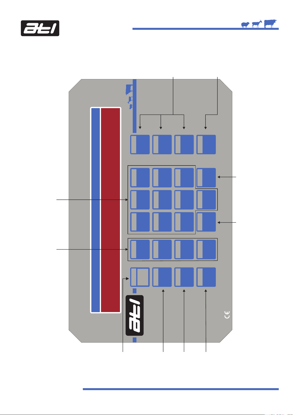
The Auto Wash Pro Front Panel........................................................................................ 6
Installing the Auto Wash Pro........................................................................................... 7
Good Practice During the Installation............................................................................... 8
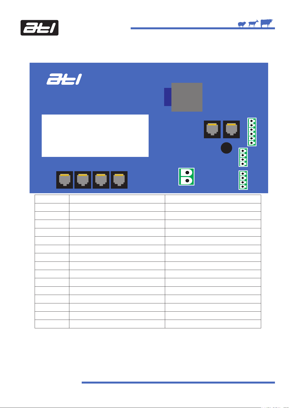
Auto Wash Pro Control PCB Wiring Connections................................................................. 9
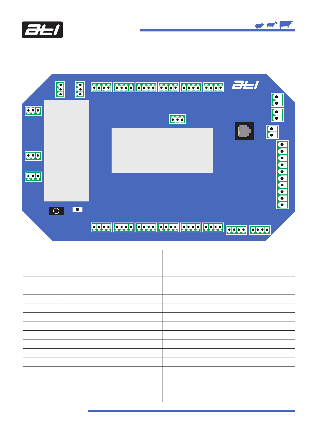
Auto Wash Pro Input/Output PCB Wiring Connections......................................................... 10
Auto Wash Pump Box 2500 Connections ......................................................................... 14
Auto Wash Pump Box 2500 PCB Connections................................................................... 15
Auto Wash Pro Layout Diagram..................................................................................... 17
Connecting the Auto Wash Pro to Contactor Switched Vacuum Pumps.................................. 18
Connecting the Auto Wash Pro to Variable Speed Vacuum Pumps......................................... 20
Setting Up the Auto Wash Pro.......................................................................................... 21
The Keypad................................................................................................................. 21
The Display................................................................................................................. 22
Entering Setup............................................................................................................ 22
Entering the Access Code.............................................................................................. 22
Navigating Through Menu Items.................................................................................... 22
The Settings Menu Structure......................................................................................... 23
The Key Buzzer Setting................................................................................................. 25
Setting the Time.......................................................................................................... 26
Setting the Date.......................................................................................................... 27
Editing Programs - See Page 45...................................................................................... 29
Editing Tasks - See Page 49............................................................................................ 29
Setting the Conductivity Difference................................................................................. 29
Setting the Vacuum Low Warning Level............................................................................ 30
Setting the Milking Vacuum Level.................................................................................... 30
Setting the Washing Vacuum Level.................................................................................. 31
Setting the Vacuum High Warning Level........................................................................... 31
Setting the Vacuum Pump Type...................................................................................... 32
Setting the Wash Trough Lock Out................................................................................... 32
Setting the Milk Tank Lock Out........................................................................................ 32
Calibration the Peristaltic Pumps - See Page 53.................................................................. 33
2 | Auto Wash Pro Manual | v1.2

© ATL Agricultural Technology Limited: July 2018
Innovation In and Out of Parlour
Index Continued
Test Displays Diagnostic................................................................................................ 33
Test Keyboard Diagnostic.............................................................................................. 34
Input/Output (I/O) Printed Circuit Board (PCB) Diagnostics................................................. 35
Input/Output (I/O) Printed Circuit Board (PCB) Test Routines............................................... 38
Control Printed Circuit Board (PCB) Serial Number.............................................................. 42
Control Printed Circuit Board (PCB) Software Version.......................................................... 42
Restore Factory Settings............................................................................................... 43
Lock Setup.................................................................................................................. 44
Editing Programs......................................................................................................... 45
Editing Tasks............................................................................................................... 49
Calibrating the Peristaltic Pumps..................................................................................... 53
Milking Mode............................................................................................................... 54
Washing Mode............................................................................................................ 55
Info Function.............................................................................................................. 58
Monthly / Six Monthly / Yearly Routine Maintenance............................................................ 62
Parlour Wash Down....................................................................................................... 62
Troubleshooting Errors.................................................................................................. 62
3 | Auto Wash Pro Manual | v1.2

Innovation In and Out of Parlour
© ATL Agricultural Technology Limited: July 2018
Manual Versions
Version 1.0 - January 2016............................First Version of Manual (Control v1.20 / IO Board v1.09)
Version 1.1 - February 2016.......................Second Version of Manual (Control v1.20 / IO Board v1.09)
Version 1.2 - July 2018..........................................Pump Box Update (Control v2.34 / IO Board 1.13)
4 | Auto Wash Pro Manual | v1.2

About the Auto Wash Pro
The Auto Wash Pro from ATL is a simple and easy to use wash controller that washes the parlour
automatically after each milking. It provides more consistent and efficient cleaning using less chemical than
manual washing irrespective of the operator. The system is programmable and it’s versatility provides an
excellent wash to any type of small to medium size milking parlour.
Control Features
Programmable settings to be optimised for every milking parlour;
Large LED display showing washing status;
Full numeric key pad, allowing easy entry of complex program information;
9 wash programs, including dedicated pre-milking key.
Auto wash key allowing programs to be started based on time of day;
Variable speed vacuum pump control
Pump Unit Features
Separate pump unit keeps electronics and chemicals apart;
Peristaltic pumps accurately dispenses chemicals at up to 2.5 litres per minute - up to a
maximum of 4 pumps;
Automatic chemical dispensing reduces operator handling of chemicals to a minimum;
Large bore hot and cold external water valves.
Other Features
Up to 3 temperature sensors, including dedicated sensors for wash trough and return water;
Pressure level sensor in wash trough;
Conductivity sensor in wash trough, allows for checking of chemical;
Controls up to 3 fixed speed or variable speed vacuum pumps;
Compressed air operated 3 way diversion valve in return line for diverting to drain or wash trough;
Vacuum sensor
22 individual 12vDC outputs to control all aspects of the milking parlour;
2 Solid State Relay outputs to switch a maximum of 24v AC or DC;
2 switched inputs allowing control of programs via external inputs;
Benefits
Easy to use - just push the Auto Wash button and the unit will automatically clean the milking
parlour for you based on the wash program for the time of day;
Electronic system - optimise settings to suit any sized parlour;
Consistent cleaning control - temperature, chemical dosing and time are all automatically
controlled irrespective of the operator;
Automatic dosing of liquid detergents - maximises operator safety and prevents excessive use of
detergents;
Wash safety lock - prevents wash start up if milk delivery line connected to milk tank;
Vacuum pumps - staggered vacuum pump switch on.
Innovation In and Out of Parlour
5 | Auto Wash Pro Manual | v1.2
© ATL Agricultural Technology Limited: July 2018

Innovation In
and Out of
Auto Wash Pro
123
45 6
7
0
89
Enter
Setup
Shift
Stop
AutoCancel
Reset é
è
ê
ç
Pause
Skip
Pre
Milking
Milk
Milk
Stone
ATL Agricultural Technology Ltd Units 1 & 2 Acorn Business Centre Oaks Drive Newmarket Suffolk CB8 7SY UK
Telephone: 0044 (0)1638 731212 Fax: 0044 (0)1638 731174 Website: www.atlagri.com E-mail: [email protected]
Insert Delete
Prog 1
Prog 2
Prog 3
Info
Prog 4
Prog 5
Prog 6
Clear
Back
Front Cover
Innovation In and Out of Parlour
© ATL Agricultural Technology Limited: July 2018
6 | Auto Wash Pro Manual | v1.2
Pause Key
Shift Key
Skip Key
Shift Function
- Back
Number Entry Keys
Setup Functions:
Shift + Key 1 - Inset when in edit Programs or edit Tasks
Key 2 & Key 6 - Move up in any menu
Shift + Key 3 - Delete when in edit Programs or edit Tasks
Key 4 & Key 8 - Move down in any menu
Program 1-6
start keys
Enter Key
Shift Function
- Setup
Info Key
Shift Function
- Clear
Cancel Key
Wash Program Keys
Auto Key: Starts the time selected program
Pre Milking: Starts the Pre-Milking Wash Program
Milk: Starts the Milking program
Milk Stone: Starts the dedicated Milk Stone program
Stop Key

Innovation In and Out of Parlour
Installing the Auto Wash Pro Control Unit and Pump Unit
The Auto Wash Pro system consists of a control unit, pump unit and power supply unit.
All of the units should be mounted on the wall to the side of the wash trough to avoid chemical gases and hot
water vapour damaging the unit.
© ATL Agricultural Technology Limited: July 2018
7 | Auto Wash Pro Manual | v1.2

Innovation In and Out of Parlour
Good Practice During the Installation
A separate mains supply and earth running directly from the consumer meter is essential.
Avoid routing the mains cable to the power supply close to other supplies especially those providing
intermittent current motors that are starting and stopping continually or high power heaters with
thermostatic control.
Terminate in a sealed, fused, double pole switched outlet fitted with a 13Amp (Type 1362) fuse or trip. A
3-pin ring main socket is not suitable in parlour conditions. All mains cabling must be contained in a firmly
secured durable conduit.
Power Supply: Siting
Fix the power supply to a wall or suitable brackets in a well ventilated area sufficiently high to avoid
physical contact or damage, leaving a gap of at least 250mm (10") between the top of the power supply
casing and the ceiling.
Position the power supply so that the output (low DC voltage) cables are as short as possible even if this
means extending the mains supply.
ATL Power Supplies: Output Voltages
ATL power supply outputs are factory set and should not be adjusted.
396 Watt 12vDC PSU 60 Watt 12vDC PSU
Input: 100 - 240vAC Input: 100 - 240vAC
Output: Nominal 12vDC Output: Nominal 12vDC
The 396 Watt 12vDC and 60 Watt 12vDC power supplies have a thermal cutout and overload protection
which removes power from the outputs in the event of an overload.
There are two indicators fitted to the base of the power supply casing; red indicates that the mains is
present and green that the output supply is available.
Control and Feeder Cables and Conduit
Cables must be kept as short as possible running directly from point to point. Cut out any excess cable
rather than leaving it coiled.
Wherever possible cables should be contained in a waterproof conduit using the correct csa cable
specified in the diagrams.
Entries must be made into the bottom of power supply or control casings but never into the
top. This will invalidate the warranty.
Strip existing cables back to bright copper before connection.
Keep multicore cables away from other cables especially those carrying mains or heavy currents. Cross
o
only at 90 where necessary and do not enclose in conduit with other cables.
© ATL Agricultural Technology Limited: July 2018
8 | Auto Wash Pro Manual | v1.2

Auto Wash Pro Control PCB Wiring Connections
The Auto Wash Pro Control PCB wiring connections are shown in the diagram and table below.
© ATL Agricultural Technology Limited: July 2018
Innovation In and Out of Parlour
Parlour Processor
5
6
Number
1
2
3
4
5
6
7
8
9
10
11
12
13
14
15 - 22
Connects To
Ethernet Cat5e - Input/Output PCB
Ethernet Cat5e - Spare
Power In -12vDC
Power In +12vDC
RS485 Cat5e Connection
+ve RS485 Power
Data A
Data B
EOL Link
Screen
-ve RS485 Power
Unused
Cable Specification
Yellow Cat5e Cable
Unused
Unused
Unused
Unused
Unused
Red Cat5e Cable
Red Cat5e Cable
Unused
Twisted Pair - Red
Twisted Pair -Black
Only Connect When Instructed by ATL
Twisted Pair Screen
Unused
Unused
1
78
9
10
11
12
13
14
15
16
17
18
19
20
21
22
9 | Auto Wash Pro Manual | v1.2
IMPORTANT - DO NOT INSTALL TWO
CABLES THROUGH 1 CABLE HOLE IN
THE 4 PORT GLAND. THIS WILL
INVALIDATE THE WARRANTY.
2 3 4

Auto Wash Pro Input/Output PCB Wiring Connections
The Auto Wash Pro Input/Output PCB wiring connections are shown in the diagram and corresponding table
below.
© ATL Agricultural Technology Limited: July 2018
Innovation In and Out of Parlour
Plantwasher
Input/Output
Board
Number
1
2
3
4
5
6
7
8
9
10
11
12
13
14
15
16
Connects To
NA
NA
NA
Conductivity Probe Screen
Conductivity Probe -ve
Conductivity Probe +ve
Temperature Probe 3 Screen
Temperature Probe 3 -ve
Temperature Probe 3 +ve
Return Water Temp Probe Screen
Return Water Temp Probe -ve
Return Water Temp Probe +ve
Wash Trough Temp Probe Screen
Wash Trough Temp Probe -ve
Wash Trough Temp Probe +ve
Hot Water Valve 1 +ve Common
49
56
57
58
59
13
14
15 16
17
24 26
25 27
32 34
33 35 43
44
45
46
47
48
52
53
54
55
50
51
67 65
66 64
83 81
82 80
87 85
86 84
92
10 | Auto Wash Pro Manual | v1.2
10
11
12
7
8
9
4
5
6
93
20 22
21 23
18
19
28 30
29 31
36 38
37 39
40
41
42
91 89
90 88
71 69
70 68
75 73
74 72
79 77
78 76 63 61
62 60
1
2
3
Cable Specification
For use by ATL only
For use by ATL only
For use by ATL only
Screened Twisted Pair Provided
0.5mm CSA

Auto Wash Pro Input/Output PCB Wiring Connections
Number
17
18
19
20
21
22
23
24
25
26
27
28
29
30
31
32
33
34
35
36
37
38
39
40
41
42
43
44
45
46
47
48
49
50
51
52
53
Connects To
Hot Water Valve 1 -ve Switched Output
Hot Water Valve 2 +ve Common
Hot Water Valve 2 -ve Switched Output
Cold Water Valve +ve Common
Cold Water Valve -ve Switched Output
Wash Line Vac Build Up +ve Common
Wash Line Vac Build Up -ve Switched
Drain Valve +ve Common
Drain Valve -ve Switched Output
Diverter Valve +ve Common
Diverter Valve -ve Switched Output
Separation Valve +ve Common
Separation Valve -ve Switched Output
End Of Wash +ve Common
End Of Wash -ve Switched Output
Vac Pump 1 +ve Common
Vac Pump 1 -ve Switched Output
Vac Pump 2 +ve Common
Vac Pump 2 -ve Switched Output
Vac Pump 3 +ve Common
Vac Pump 3 -ve Switched Output
Vac Pump Stop +ve Common
Vac Pump Stop -ve Switched Output
RS232 /485 Vac Pump Inverter Screen
RS232 / 485 EOL
RS232 /485 Vac Pump Inverter Rx / A
RS232 /485 Vac Pump Inverter Tx / B
+12vDC IN
-ve 12vDC IN
+12vDC OUT (to pump box)
-ve 12vDC OUT (to pump box)
+ve Peristaltic Pump Supply
-ve Peristaltic Pump Supply
Ethernet Cat5e - Parlour Processor
+ve Peristaltic Pump 1 (Acid)
-ve Peristaltic Pump 1 (Acid)
+ve Peristaltic Pump 2 (Alkaline)
© ATL Agricultural Technology Limited: July 2018
Innovation In and Out of Parlour
11 | Auto Wash Pro Manual | v1.2
Cable Specification
Blue in 0.5mm 10 way Cable Provided
0.5mm CSA
0.5mm CSA
0.5mm CSA
Gray in 0.5mm 10 way Cable Provided
0.5mm CSA
Yellow/Green in 0.5mm 10 way Cable Provided
0.5mm CSA
0.5mm CSA
0.5mm CSA
Brown in 0.5mm 10 way Cable Provided
0.5mm CSA
0.5mm CSA
0.5mm CSA
0.5mm CSA
0.5mm CSA
0.5mm CSA
0.5mm CSA
0.5mm CSA
0.5mm CSA
0.5mm CSA
0.5mm CSA
0.5mm CSA
Not Used
Not Used
Not Used
Not Used
2.5mm CSA
2.5mm CSA
Red in 1.0mm 10 way Cable Provided
Black in 1.0mm 10 way Cable Provided
2.5mm CSA
2.5mm CSA
Yellow Cat5e Cable
Brown in 1mm 10 way Cable Provided
Orange in 1mm 10 way Cable Provided
Yellow/Green in 1mm 10 way Cable Provided

Auto Wash Pro Input/Output PCB Wiring Connections
Number
54
55
56
57
58
59
60
61
62
63
64
65
66
67
68
69
70
71
72
73
74
75
76
77
78
79
80
81
82
83
84
85
86
87
88
89
90
Connects To
-ve Peristaltic Pump 2 (Alkaline)
+ve Peristaltic Pump 3 (Detergent)
-ve Peristaltic Pump 3 (Detergent)
+ve Peristaltic Pump 4
-ve Peristaltic Pump 4
-ve Peristaltic Pumps
Input 2 +ve Switch Input
Input 2 -ve Switch Common
Input 1 +ve Switch Input
Input 1 -ve Switch Common
Milk Tank Lockout Input
Milk Tank Lockout Common
Wash Trough Lockout Input
Wash Trough Lockout Common
Solid State Relay Output 2b
Solid State Relay Output 2a
Solid State Relay Output 1b
Solid State Relay Output 1a
Output 5 +ve Common
Wash LED -ve Switched
Output 4 +ve Common
Milk LED -ve Switched
Output 3 +ve Common
Output 3 -ve Switched
Output 2 +ve Common
Output 2 -ve Switched
Output 1 +ve Common
Output 1 -ve Switched
Auto Drain +ve Common
Auto Drain -ve Switched
Pulsation +ve Common
Pulsation -ve Switched
AirBlast +ve Common
AirBlast -ve Switched
Milk Pump 2 +ve Common
Milk Pump 2 -ve Switched
© ATL Agricultural Technology Limited: July 2018
Innovation In and Out of Parlour
12 | Auto Wash Pro Manual | v1.2
Cable Specification
Blue in 1mm 10 way Cable Provided
Purple in 1mm 10 way Cable Provided
Gray in 1mm 10 way Cable Provided
White in 1mm 10 way Cable Provided
Pink in 1mm 10 way Cable Provided
1mm CSA
1mm CSA
0.5mm CSA
0.5mm CSA
0.5mm CSA
0.5mm CSA
Screened Twisted Pair Provided
Use Appropriate Cable
0.5mm CSA
Red 0.5mm CSA in 10 Way Cable
0.5mm CSA
Black 0.5mm CSA in 10 Way Cable
0.5mm CSA
0.5mm CSA
0.5mm CSA
0.5mm CSA
0.5mm CSA
0.5mm CSA
0.5mm CSA
White 0.5mm CSA in 10 Way Cable
0.5mm CSA
0.5mm CSA
0.5mm CSA
0.5mm CSA
0.5mm CSA
0.5mm CSA

Auto Wash Pro Input/Output PCB Wiring Connections
Number
91
92
93
94
Connects To
Milk Pump 1 +ve Common
Milk Pump 1 -ve Switched
Wash Trough Level Input
Vacuum Level Input
© ATL Agricultural Technology Limited: July 2018
Innovation In and Out of Parlour
13 | Auto Wash Pro Manual | v1.2
Cable Specification
0.5mm CSA
Tubing Provided
Tubing Provided

Innovation In and Out of Parlour
© ATL Agricultural Technology Limited: July 2018
14 | Auto Wash Pro Manual | v1.2
Auto Wash Pump Box 2500 Connections
The Auto Wash Pump Box connections are shown in the diagram below.
Pump 1
Acid
Pump 2
Alkali
Pump 3
Detergent
Optional
Pump 4

Auto Wash Pro Pump Box PCB Wiring Connections
The Auto Wash Pro Pump Box PCB wiring connections are shown in the diagram and corresponding table
below.
© ATL Agricultural Technology Limited: July 2018
Innovation In and Out of Parlour
Number
1
2
3
4
5
6
7
8
9
10
11
12
13
14
15
16
Connects To
Unused
Unused
Unused
Washing LED
Milking LED
Diverter Output
Wash Line Vacuum Build Up Output
Hot Water 1 Output
Cold Water Output
Optional Hot Water 2 Output
Pump 1 (Acid) +ve Output
Pump 1 (Acid) -ve Output
Pump 2 (Alkali) +ve Output
Pump 2 (Alkali) -ve Output
Pump 3 (Detergent) +ve Output
Pump 3 (Detergent) -ve Output
15 | Auto Wash Pro Manual | v1.2
Cable Specification
Orange from 0.5mm 10 way
Purple from 0.5mm 10 way
Pink from 0.5mm 10 way
Red from 0.5mm 10 way
Black from 0.5mm 10 way
Brown from 0.5mm 10 way
Yellow / Green from 0.5mm 10 way
Blue from 0.5mm 10 way
Gray from 0.5mm 10 way
White from 0.5mm 10 way
Brown from 1mm 10 way
Orange from 1mm 10 way
Yellow / Green from 1mm 10 way
Blue from 1mm 10 way
Purple from 1mm 10 way
Grey from 1mm 10 way
30
29
26
25
48
47
46
45
28
27
40
39
36
35
34
33
32
31
38
37
20
19
16
15
14
13
12
11 18
17
10
9
6
5
4
3
2
18
7
24
23
22
21
414243 44
5
6

Auto Wash Pro Pump Box PCB Wiring Connections
Number
17
18
19
20
21
22
23
24
25
26
27
28
29
30
31
32
33
34
35
36
37
38
39
40
41
42
43
44
45
46
46
47
Connects To
Pump 4 +ve Output
Pump 4 -ve Output
-ve System Power IN
+ve System Power IN
+ve Red Wire from Pump 1
-ve Black Wire from Pump 1
+ve Red Wire from Pump 2
-ve Black Wire from Pump 2
+ve Red Wire from Pump 3
-ve Black Wire from Pump 3
+ve Red Wire from Pump 4
-ve Black Wire from Pump 4
-ve System Power OUT
+ve System Power OUT
Diverter Solenoid -ve Switched Output
Diverter Solenoid +ve Common
Optional Vac Build Up -ve Switched O/P
Optional Vac Build Up +ve Common
Hot Water 1 -ve Switched Output
Hot Water 1 +ve Common
Cold Water -ve Switched Output
Cold Water +ve Common
Optional Hot Water 2 -ve Switched O/P
Optional Hot Water 2 +ve Common
+ve LED Common
-ve Washing LED Output
+ve LED Common
-ve Milking LED Output
Unused
Unused
Unused
Unused
© ATL Agricultural Technology Limited: July 2018
Innovation In and Out of Parlour
16 | Auto Wash Pro Manual | v1.2
Cable Specification
White from 1mm 10 way
Pink from 1mm 10 way
Black from 1mm 10 way
Red from 1mm 10 way
+ve Red Wire from Pump 1
-ve Black Wire from Pump 1
+ve Red Wire from Pump 2
-ve Black Wire from Pump 2
+ve Red Wire from Pump 3
-ve Black Wire from Pump 3
+ve Red Wire from Pump 4
-ve Black Wire from Pump 4
Unused
Unused
-ve Black Wire from Diverter Solenoid
+ve Red Wire from Diverter Solenoid
-ve Black Wire from Optional Vac Build Up Solenoid
+ve Red Wire from Optional Vac Build Up Solenoid
-ve Black Wire from Hot Water 1 Solenoid
+ve Red Wire from Hot Water 1 Solenoid
-ve Blue Wire from Twin Wire to Cold Water Valve
+ve Brown Wire from Twin Wire to Cold Water Valve
-ve Black Wire from Optional Hot Water 2 Solenoid
+ve Red Wire from Optional Hot Water 2 Solenoid
+ve Red Wire to Milking LED
-ve Blue Wire to Milking LED
+ve Red Wire to Washing LED
-ve White Wire to Washing LED
Unused
Unused
Unused
Unused

Auto Wash Pro Layout Diagram
© ATL Agricultural Technology Limited: July 2018
Innovation In and Out of Parlour
17 | Auto Wash Pro Manual | v1.2
To Parlour
Wash Line
Wash Trough
Pump Box 2500
Delivery
Line
Connection
With
Milk Tank
Lockout
Switch
To Drain
Acid Alkali Detergent
Recirculation
Hot Water
Valve
Divertor
Valve
Vacuum Build
Up Valve
Cold Water
Valve
396 Watt 12vDC
Power Supply
Auto Wash Pro
_
+
+
+
_

Connecting the Auto Wash Pro to Contactor Switched Vacuum Pumps
Connecting from the Plantwasher Input/Output Printed Circuit Board (PCB)
Start 1-ve - White - Connect into connection number 33
Start 2 -ve - Black (from Black/White pair) - Connect into connection number 35
Stop -ve - Red - Connect into connection number 39
Common + - Black (from Black/Red pair) - Connect into connection number 38
Connecting into the Vacuum Pump Starter Control Box
Innovation In and Out of Parlour
© ATL Agricultural Technology Limited: July 2018
18 | Auto Wash Pro Manual | v1.2
Plantwasher
Input/Output
Board
32 34
33 35
Wire connects to
Vacuum Pump
Starter Control
Box
Start
1
Relay
Stop
1
Relay
Start
2
Relay
Stop
2
Relay
Common
Normally Open
Coil
Normally Closed
4 Core Cable
to Contactor
in Starter Box
for Vacuum
Pump 1
4 Core Cable to
Contactor in
Starter Box
For Vacuum
Pump 2
Green
Green
Yellow
Red
Yellow
Red
Blue Blue
Red
Black (1)
White
Black (2)
Red Red Red
Red
Black (1) from Black/White Pair
Black (2) from Black/Red Pair From Auto
Wash 365
Control
36 38
37 39

Connecting the Auto Wash Pro to Contactor Switched Vacuum Pumps Continued
Connecting to the Vacuum Motor Starter Box
Red, yellow, blue and green wires are from the Vacuum Pump Starter Control Box.
Motor Wiring
Innovation In and Out of Parlour
© ATL Agricultural Technology Limited: July 2018
19 | Auto Wash Pro Manual | v1.2
A13
B
A1
K1
A2
95
X BREAK HERE
95
14
L1
L2
STOP
(RED)
START
(GREEN)
96
14
13
A2
K1
RED
YELLOW
BLUE
GREEN
(Remove Black Loopwire)
MOTOR
FT1
T2 T3T1
4 62
3 51
A
B
L2 L3L1
K1
13
14

Innovation In and Out of Parlour
© ATL Agricultural Technology Limited: July 2018
Setting up the Auto Wash Pro
Before it can be used, the Auto Wash Pro must be setup. This is outlined in the following pages.
The Keypad
There are 24 keys on the keypad. 5 are for washing programs - Pre-Milking, Milk Stone, Prog 1, Prog 2 and
Prog 3 - the Milk key is for milking mode, the Auto key provides a simple single key which can be
programmed to run different wash programs based on the time of day and day of week. The Info key
provides information on the wash, and the remaining function keys are Stop, Pause, Skip, Enter and Shift.
There a number of keys that are dual function with the use of the Shift key - these provide the programming
and user functions when a wash program is running. The other function of the key is shown in the grey box at
the top of the key. The keys which have dual function are Cancel, 1, 2, 3, 4, 6, 8, Prog 1, Prog 2, Prog 3, Skip,
Enter and Info.
The keypad is constructed from a tough membrane overlaying individual key switches. This is a proven,
reliable construction which will last for many years provided it is cleaned only with warm soapy water and not
hosed down at high pressure.
The Display
The display has two areas. The Mode area shows the current mode - either Idle when neither milking or
washing, Milk when in Milking Mode or PRE, MST, PG1, PG2, PG3, PG4, PG5 or PG6 when in Washing Mode.
The Function area shows where the control is in Wash Mode or displays the time in Milking or Idle Modes.
The Auto Wash Pro Control is very energy efficient; power saving was an important element of the design
criteria.
IDLe 15--48--44
Mode Function Window
20 | Auto Wash Pro Manual | v1.2
123
45 6
7
0
89
Enter
Setup
Shift
Stop
AutoCancel
Reset é
è
ê
ç
Pause
Skip
Pre
Milking
Milk
Milk
Stone
Insert Delete
Prog 1
Prog 2
Prog 3
Info
Prog 4
Prog 5
Prog 6
Clear
Back
Table of contents
Popular Washer manuals by other brands

Gorenje
Gorenje WA71141 Instructions for use

Alliance Laundry Systems
Alliance Laundry Systems AWN432SP113TW01 user guide

Haier
Haier HLP24E Service manual

Alliance Laundry Systems
Alliance Laundry Systems UW100AV operation & maintenance

Palsonic
Palsonic PAL650TT owner's manual

Electrolux
Electrolux UFW 47 K 8161 user manual