1
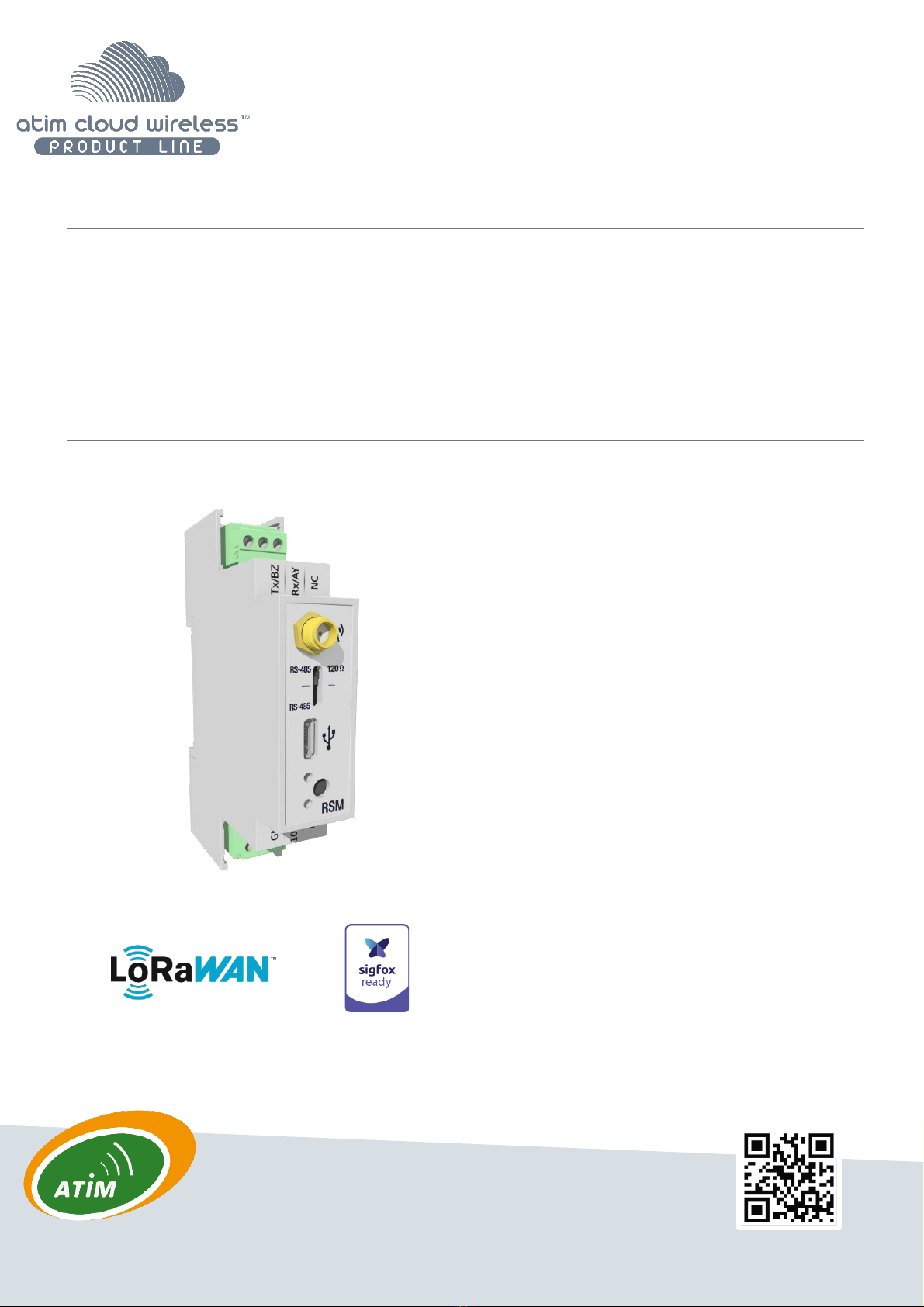
ATIM_ACW-DINRSM_UG_EN_V2.8
TABLE OF CONTENTS
Document version history .......................................................................................................................................................2
Disclaimer.................................................................................................................................................................................2
Trademarks and copyright.......................................................................................................................................................2
Declaration of compliance.......................................................................................................................................................3
Environmental recommendations ..........................................................................................................................................3
a. Environment 3
b. Radio 4
Technical specifications ...........................................................................................................................................................5
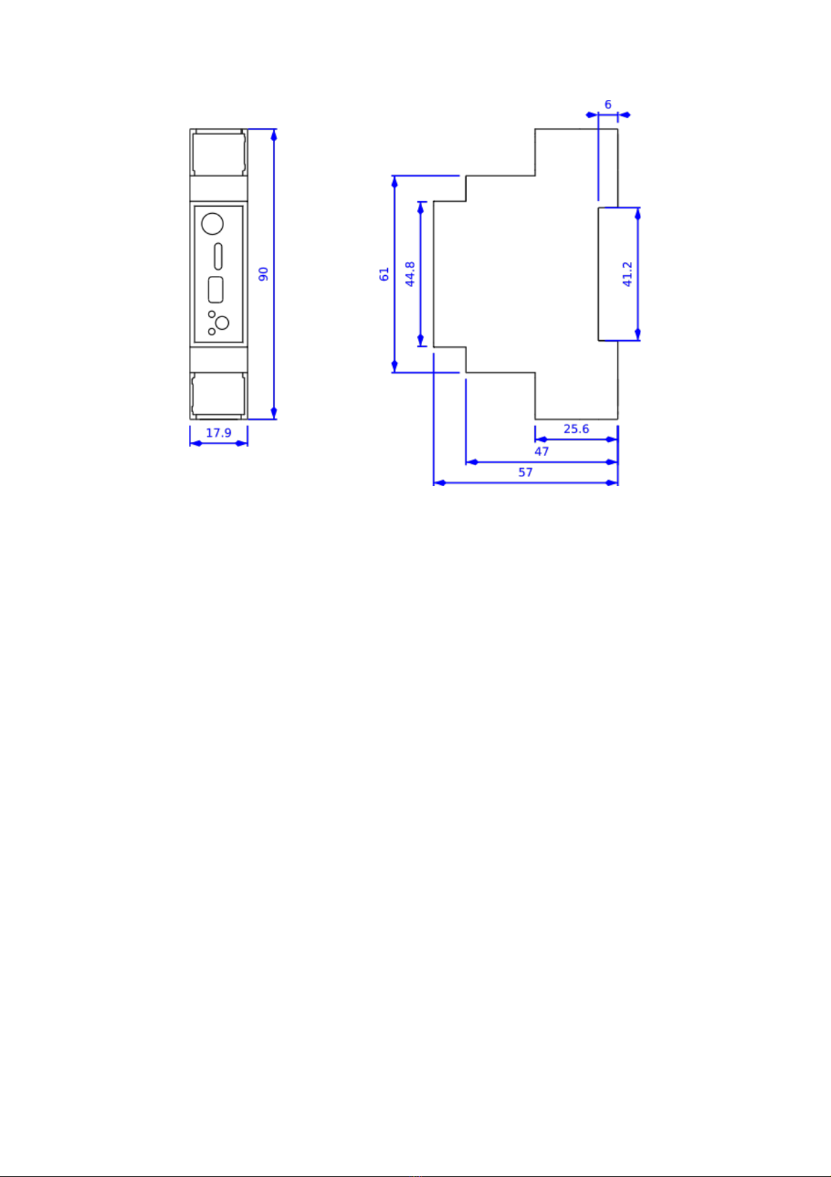
Installation................................................................................................................................................................................6
c. Positioning 6
d. Connecting the modem 7
c. Push button 8
d. Interpreting the indicator lights 8
Normal start-up behavior........................................................................................................................................................9
Parameter settings and configuration ....................................................................................................................................9
a. Parameter settings 9
b. Configuration via USB 12
Transmitting information on IoT networks (Sigfox/LoRaWAN)...........................................................................................17
a. Keep-alive frame 17
b. Periodic frame (or triggered by pressing button) 17
c. Error frame 17
Receiving information from IoT networks (Sigfox/LoRaWAN).............................................................................................19
a. Parameters 19
b. Commands 23
Troubleshooting.....................................................................................................................................................................29
a. The modem cannot be configured via USB or the configuration tool page does not refresh 29
b. Radio data not received 29
c. Modem LED is not flashing 29
Technical support...................................................................................................................................................................30