Atlas TTC305 User manual

REV. 01 2014 1 / 41

REV. 01 2014 2 / 41
PRINTING CHARACTERS AND SYMBOLS
Throughout this manual, the following symbols and printing characters are used to facilitate reading:
Indicates the operations which need proper care
Indicates prohibition
Indicates a possibility of danger for the operators
BOLD TYPE Important information
WARNING: before operating the machine, read the manual carefully for all
proper operations and better functioning.

REV. 01 2014 3 / 41
CONTENTS
1 INTRODUCTION 4
1.1 - INTRODUCTION
1.2 MACHINE IDENTIFICATION DATA
1.3 MANUAL KEEPING
4
4
4
2 GENERAL INFORMATION 5
2.1 INTENDED USE
2.2 GENERAL SAFETY PRECAUTIONS
2.3 SAFETY DEVICES
2.4 PRODUCT DESCRIPTION
2.5 TECHNICAL SPECIFICATION
2.6 IDENTIFYING WARNING SIGNS
5
5
5
6
6
7
3 TRANSPORTATION AND UNPACKING 8
3.1 TRANSPORTATION
3.2 UNPACKING
8
8
4 INSTALLATION 9
4.1 INSTALLATION SPACE REQUIRED
4.2 WORKPLACE REQUIRED
4.3 FOUNDATION REQUIREMENT
4.4 ELECTRIC HOOK UP
9
9
9
10
5 OPERATION 11
5.1 CONTROLS
5.2 CORRECT OPERATION CHECKS
5.3 LOCKING THE WHEEL
5.4 LIGHT-ALLOY RIM LOCKING
5.5 DEMOUNTING TUBELESS TIRES
5.6 MOUNTING TUBELESS TIRES
11
12
13
14
14
15
6 ORDINARY MAINTENANCE 16
7 TROUBLE SHOOTING
17
8 MOVING, STORING AND SCRAPPING
8.1 MOVING THE MACHINE
8.2 STORING
8.3 SCRAPPING A MACHINE
18
18
18
18
9 OPTIONAL ACCESSORIES
19
10 HYDRAULIC SCHEME AND ELECTRIC DIAGRAM 20
11 PARTS LIST 22

REV. 01 2014 4 / 41
CHAPTER 1 – INTRODUCTION
1.1 INTRODUCTION
Thank you for purchasing a product from the line of truck tire changers. The machine has been
manufactured in accordance with the very best quality principles. Follow the simple instructions
provided in this manual to ensure the correct operation and long life of the machine. Read the entire
manual thoroughly and make sure you understand it.
1.2 MACHINE IDENTIFICATION DATA
A complete description of the “Tire Changer Model” and the “Serial number” will make it easier for
our technical assistance to provide service and will facilitate delivery of any required spare parts. For
clarity and convenience, we have inserted the data of your machine in the box below. If there is any
discrepancy between the data provided in this manual and that shown on the name plate fixed to the
wheel balancer, the latter should be taken as correct.
1.3 MANUAL KEEPING
For a proper use of this manual, the following is recommended:
Keep the manual near the lift, in an easily accessible place.
Keep the manual in an area protected from the damp.
Use this manual properly without damaging it.
Any use of the machine made by operators who are not familiar with the instructions and
procedures contained herein shall be forbidden.
This manual is an integral part of the manual: it shall be given to the new owner if and when the
machine is resold.
The illustrations have been made out of prototypes pictures. It is therefore
possible that some parts or components of standard production differ from those
represented in the pictures.
TO THE READER
Every effort has been made to ensure that the information contained in this manual is correct, complete
and up-to date. The manufacturer is not liable for any mistakes made when drawing up this manual and
reserves the right to make any changes due the development of the product, at any time
LOGO
Type:
Volt Amp Kw
Ph Hz
Year of manufacturing:

REV. 01 2014 5 / 41
CHAPTER 2 – GENERAL INFORMATION
2.1 INTENDED USE
This tire changer has been designed and manufactured exclusively to be put on a can for
removing and mounting truck, bus and commercial van tires from/onto rim bores from 8" to
23" and a tire at maximum diameter of 55".
In particular the manufacturer cannot be held responsible for any damage caused through the
use of this tire changer for purposes other than those specified in this manual, and therefore
inappropriate, incorrect and unreasonable.
2.2 GENERAL SAFETY PRECAUTIONS
The machine should only be used by duly authorized and trained personnel.
The machine should not be used for purposes other than those described in the instruction
manual.
Under no way should the machine be modified except for those modifications made explicitly
by the manufacturer.
Never remove the safety devices. Any work on the machine should only be carried out by
specialist personnel.
Any tampering or modification to the equipment carried out without the manufacturer’s prior
authorization will free him from all responsibility for damage caused directly or indirectly by
the above actions.
Removing or tampering with safety devices immediately invalidates the guarantee.
The tire changer comes complete with instruction and warning transfers which are designed
to be long-lasting. If they should for any reason be damaged or destroyed, please ask
immediately for replacements from the manufacturer.
The machine operator should avoid wearing clothes with flapping edges. Make sure that
unauthorized personnel do not approach the machine during the work cycle.
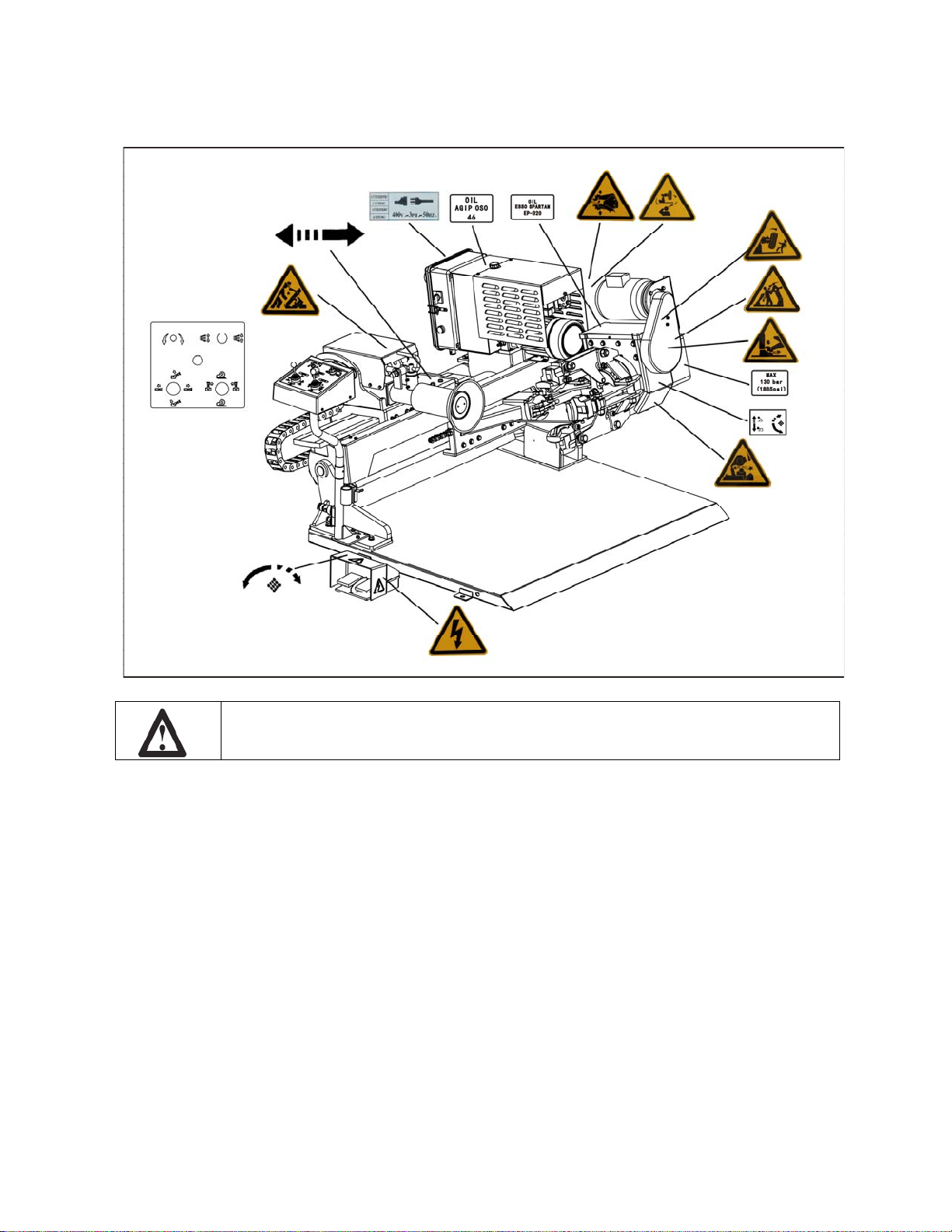
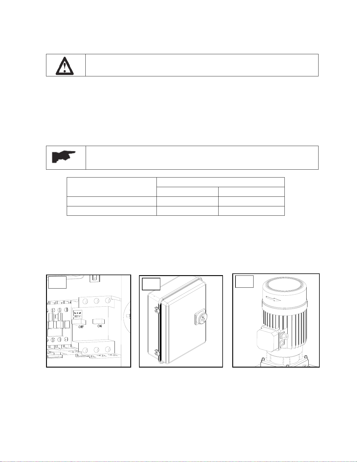
2.3 SAFETY DEVICES
The tire changer has a number of safety devices designed to
guarantee the upmost safety:
Check valve on the spindle opening hydraulic line
(inside the swivel connector, see fig. B/1). This
prevents the wheel from falling from the spindle if the
hydraulic line is accidentally broken.
Pressure relief valve set at 130 bar ± 10% (see fig.
B/2). This limits the pressure in the hydraulic line and
ensures correct operation of the plant.
Pump motor overload cut-off (inside the electric
enclosure). This cut prevents the motor from burning
out if it overheats.
Check valve on the chuck arm lifting hydraulic line.
It prevents the chuck arm from descending when any
accidental break occurs in the hydraulic line. .

REV. 01 2014 6 / 41
2.4 PRODUCT DESCRIPTION
1. Electric system
2. Jaw
3. Chuck arm
4. Tool roller
5. Self-centering chuck
6. Control unit
7. Foot pedal
8. Hydraulic power unit
9. Carriage
10. Tool holder arm
11. Frame plate
2.5 TECHNICAL SPECIFICATION
Pump motor 2 HP 220V +/- 5% (209-231volts) 1 phase.
A 30 amp breaker is required.
Handles rim from 13” – 26”
Max. tire diameter 55"
Max. tire width 30 1/2"
Max. wheel weight 838 LBS
Gross weight 1490
Noise level in working condition < 70 dB (A)
1
2
3
4
5
6
7
8
9
A
10
11

REV. 01 2014 7 / 41
2.6 IDENTIFYING WARNING SIGNS
Unreadable and missing warning labels must be replaced immediately. Do not
use and add any object that could prevent the operator from seeing the labels.

REV. 01 2014 8 / 41
CHAPTER 3 – TRANSPORTATION AND UNPACKING
3.1 TRANSPORTATION
The machine must be transported in its
original packaging and kept in the position
shown on the package itself.
The packaged machine may be moved by
means of a fork lift truck of suitable
capacity. Insert the forks at the points shown
in fig. A/2.
3.2 UNPACKING
Remove the packing materials.
After removing the packaging from the
ma
chine, make sure to check it withoutany
damage
.
If in doubt do not use the machine and contact your retailer.
A/2
660KG

REV. 01 2014 9 / 41
CHAPTER 4 – INSTALLATION
4.1 INSTALLATION SPACE REQUIRED
When choosing the place of installation, make sure that it complies with current
safety at work regulations.
The machine must be located on a flat floor of solid construction, preferably concrete. If the
floor is uneven or broken, the machine will be not stable and the platform roller cannot move
freely.
If the machine is installed outside it must be protected by a lean-to.
The following work environment conditions are applicable:
-Relative humidity from 30-95% without condensation;
-Temperature from 32-130°F.
4.2 WORKPLACE REQUIRED
Maximum machine space requirements are with a
minimum distance from walls as shown in the diagram
(see fig. B/5).
These measurements are also the tire changer working area. Persons other than
specially trained and authorized operators are extremely forbidden to enter this
area.
Position the tire changer with the tool holder arm (10/fig. A) lowered all the way and the jaws
(2/fig. A) closed.
4.3 FOUNDATION REQUIREMENT
The tire changer should be installed on a leveled concrete floor at least 20cm thick with a minimum
concrete quality of B25 in accordance with DIN 1045 requirements (foundations).
If a floor of this type is not available on site, fastening points of the specified concrete quality are
acceptable.
Surface, on which the tire changer is to be installed, must be flat and well leveled in all
directions..
Inclination up to 0.25% relative to the horizontal can be compensated using suitable shims,
wedges or the alike.

REV. 01 2014 10 / 41
4.4 ELECTRIC HOOK UP
Any electric connection job must be carried out by professionally qualified
personnel.
Check to make sure the characteristics of your systems correspond to those required by the
machine. The supply voltage (and main frequency) is given on the machine nameplate. It
cannot be changed.
Connect the machine to the generator unit.If the machine does not include the electric plug, the
user must set one, which must conforms to the voltage of the machine, in compliance with the
regulations in force.
The machine should not be started up without proper grounding.
It is absolutely essential that:
The current intake is adequately protected against over currents with fuses or
automatic magneto-thermic switch with rated value as shown in the table.
Power supply Rated current
Fuse Switch
220V/230V – 3ph – 50/60Hz 25A AM 25A
380V/440V – 3ph – 50/60Hz 16A AM 16A
Open the control panel;
Switch the breaker on (fig. B/3)
Switch on the electric panel (fig. B/7) and check that the gearbox motor rotation corresponds to
the indicating arrow (fig. B/6).
If not, switch two wires in the plug.
B/3 B/7 B/6

REV. 01 2014 11 / 41
CHAPTER 5 – OPERATION
5.1 CONTROLS
The control unit (fig. C) can be operated as follows:
Do not permit the electric control panel to get wet!
Joystick 1 (1/fig. C):
Move it to position [a] to raise the chuck arm (3/fig. A).
Move it to position [b] to lower the chuck arm.
Move it to position [c] to moves the carriage (9/fig. A) and the chuck arm towards each other.
Move it to position [d] moves the carriage and the chuck arm away from each other.
C
1
2
3 5
4
6

REV. 01 2014 12 / 41
Joystick 2 (2/fig. C):
Move it to position [a] to raise the tool holder arm (10/fig. A) out of working position.
Move it to position [b] to lower the tool holder arm to the working position.
Move it to position [c] to retract the tool roller (4/fig. A) back.
Move it to position [d] to extend the tool roller forward.
Joystick 3 (3/fig. C):
Move it to position [c] or [d] to rotate the self-centering chuck (5/fig. A) in the same direction as
shown by the arrows on the control panel.
This operation can be carried out by depressing the foot pedal.
Chuck switch (4/fig. C):
Move it to position [c] to open the self-centering chuck.
Move it to position [d] to close the self-centering chuck.
Emergency button (5/fig. C):
For emergencies, press it to cut out the tire changer power supply.
Foot pedal (6/fig. C):
When pressed on the left or right side rotates the self-centering chuck in the same direction as
shown by the arrows placed on the foot pedal.
This operation can be carried out by operaring the joystick 3.
5.2 CORRECT OPERATION CHECKS
Before using the tire changer, make sure that it is positioned correctly on the
ground.
Do not move your face close to the tool when you raise it.
When the chuck arm is lowered, there is always a potential for crushing anything
in its movement range. Always work from position given in the instructions keep
well out of working range of the various moving arms.
Before use the tire changer, a number of checks should be made to ensure it works correctly.
Operate the joysticks and the switches described in the chapter 5.1 and be sure that every control
works correctly.
Check to be certain the hydraulic circuit is working correctly:
Move the chuck switch (4/fig. C) towards the top until the chuck is fully extended.
Hold the switch lever in this position (top) and check if the pressure shown on the gauge on the
swivel fitting is 130bar ±10%. DO NOT USE THE MACHINES IF THE PRESSURE
SHOWN IS NOT AS INDICATED HERE AND THEN CALL FOR THE SERVICE.

REV. 01 2014 13 / 41
5.3 LOCKING THE WHEEL
Operate the joystick 2 (2/fig. C) to raise the tool holder
arm (10/fig. A) out of the working position.
Operate the joystick 1 (1/fig. C) to raise or lower the
chuck arm until the chuck is centered with the rim.
With the jaws (2/fig. A) are closed, bring the wheel up to
the chuck.
Operate the chuck switch (4/fig. C) to open the chuck
and lock the rim internally in the best position based on
the type of the rim according to figs E/1-E/2-E/3-E/4-
E/5 and E/6.
When the chuck arm is lowered, there is always a potential for crushing
anything in its movement range. Always work from position given in the
instructions keep well out of working range of the various moving parts.
In locking the wheel, make sure that clamps
are properly positioned on the rim, so as to
prevent the tire from falling.
This operation can be extremely dangerous.
Do it manually only if you are certain you
can keep the wheel balanced.
For large and heavy tires an adequate lifting
device must be used.
Always remember that the safest locking is
on the central FLANGE.
For rims with channel, clamp the wheel so
that the channel is near the outside of the
rim (fig. E/1).
Do not leave the work area with a wheel
clamped on the tire changer and lifted up
from the floor.

REV. 01 2014 14 / 41
5.4 LIGHT-ALLOY RIM LOCKING
The jaw protection kit CC-F100100 can be available upon
request, are specially designed for operating on light alloy
rims without damaging them.
The protections are to be inserted (bayonet-like mounting)
into the clamp support of the self-centering chuck (see fig.
E/7).
Lock the rim as illustrated in fig. E/8. The specially-made
pliers YC8-F200000 should be attached to the outside edge
of the alloy rim at the highest point.
5.5 DEMOUNTING TUBELESS TIRES
Before removing the tire, lubricate the beads carefully to
protect them from being possible damages to facilitate
the removing operations.
Lock the wheel on the self-centering chuck, as
previously described, and ensure that the tire is deflated.
Lower the tool-holder arm (10/fig. A) into is working position.
Operate the joystick to move the wheel until the roller just touches the edge of the rim as shown in
the figure E/9.
Rotate the wheel and at the same time advance the roller with small movements forward according
to the profile of the rim (ref. fig. E/10).
Always check to be certain that the arm is
corrected hooked to the carriage.
A mechanical lifting device must be used
when handling wheels weighing more than
110kg.

REV. 01 2014 15 / 41
Continue until the first bead is fully detached. To
facilitate this operation, lubricate the bead and the
edge of the rim with tire lubricant whilst the wheel is
rotated.
Bring the tool-holder arm (10/fig. A) away from the rim. Raise the tool holder arm to its non-
working position, shift it and re-hook it in its second work position.
Repeat the operation previously described until the second bead is completely detached.
Go on pushing the tire until the rim comes completely out.
5.6 MOUNTING TUBELESS TIRES
Make sure that the rim is locked on the self-centering chuck.
Lubricate the beads and rim carefully to facilitate the mounting
operations.
Fix the pliers at the outer rim edges at its highest point. Make
sure the clip is firmly attached to the rim.
Lower the chuck to allow locking the first bead with the pliers
(make sure it at the high point).
Lift the rim with the tire fixed and turn it anticlockwise about
15-20 cm. The tire will be positioned tilted across the rim.
Lower the tool-holder arm into is working position.
Operate the joystick 1 to position the roller against the second
tire bead and turn the tire until the pliers is at the lowest
position. The first bead should be set on the rim at this time.
Position the roller at a distance of 4-5mm from the rim and
press on the second tire bead in order to fit the pliers (E/11).
Turn clockwise and lubricate the beads and the rim with the
proper grease. At the same time, advance the roller with small
movements towards to the rim center until the tire is completely
set on the rim as shown in the figure E/12.
Remove the pliers out of the rim and bring the tool-holder arm
out of the working position.
Lower the chuck, and then close the chuck jaw to set the wheel
on the frame plate vertically.
To avoid all risks, rotate the wheel
clockwise when operating on the outside
plane and anticlockwise when operating
on the inside plane.
Do not keep your hands on the tool when setting it in working position so as to
avoid any possible crushing between the tire and the tool.
A mechanical lifting device must be used when handling wheels weighing more than
240 lbs.
Tire inflation must be done by placing the tire inside the safety cage.

REV. 01 2014 16 / 41
CHAPTER 6 - ORDINARY MAINTENANCE
To ensure that this tire changer works perfectly over the years, carry out the routine maintenance
schedule described below:
1) Lubricate the following parts from time to time, after a thorough cleaning with naphtha:
the various swivels on the spindle
the tool bracket slide runner
the carriage guide plate.
2) Grease the chuck arm cylinder from time to time and also its swivel using ordinary lubricating
grease.
3) From time to time check the oil level in the hydraulic power pack. Use the dipstick under the
reservoir cap.
If necessary top up with Esso Nuto H46 or similar hydraulic oil (eg, Agip Oso 46, Shell Tellus Oil 46,
Mobil DTE 25, Castrol Hyspin AWS 46, Chevron RPM EP Hydraulic Oil 46, BP Energol HLP).
4) From time to time check the oil level in the gear unit which, when the tool carrier bracket is
completely lowered at end travel, should not show the sight glass on the gear casing as completely
empty. If necessary top up with Esso Spartan EP 320 or similar oil (eg, Agip F1 REP 237, BP GRX P
320, Chevron Gear Compound 320, Mobil Gear 632, Shell Omala Oil 320, Castrol Alpha SP 320).
If the oil in the gear unit or the hydraulic power pack has to be changed, note that
the gear unit casing and the power pack reservoir have specific drain plug.
Each maintenance operation must be effected only after the disconnection of the
plug from electric network.
Refer to the user and maintenance manuals for details on the routing
maintenance of the generator and the compressor.
Dispose of the used oil following the present legislation on the matter.

REV. 01 2014 17 / 41
CHAPTER 7 - TROUBLE SHOOTING
TROUBLE:POSSIBLE CAUSE:SOLUTION:
After having switched on the
power switch, the pilot lamp
does not light on and no control
can function.
The power plug is not inserted.
Insert the plug correctly in its
socket.
No power from the mains
electric supply. Reset the mains electric
supply.
After having switched on the
power switch, the pilot lamp
light on but the motor on the
hydraulic power pack does not
function.
The circuit breaker is not
switched on. Switch on the circuit breaker.
If, despite of the above mentioned indications the tire changer does not work
properly, do not use it and call for technical assistance.

REV. 01 2014 18 / 41
CHAPTER 8 – MOVING, STORING AND SCRAPPING
8.1 MOVING THE MACHINE
To move the machines, follow these instructions:
1) Completely fold down the tire changer.
2) Close completely the jaws of the chuck.
3) Unscrew the screws that secure the tire changer on the van.
4) Use a forklift truck of suitable loading capacity, take the tire changer off the van and put it away in a
sheltered and covered place.
8.2 STORING
If the machine as to be stored for a long time (3-4 months) you have to:
1) Grease all the parts that could be damaged if they dry out:
the self-centering chuck
the tool holding arm
the slides of the carriage
the tool
2) Empty oil/hydraulic fluid reservoirs and wrap the machine in a sheet of protective plastic to prevent
dust from reaching the internal working parts.
If the machine as to working again after a long storing period, it is necessary to:
fill the oil into the reservoirs again.
8.3 SCRAPPING A MACHINE
When your machine’s working life is over and it can no longer be used, it must be made inoperative by
removing any connection to power sources.
These units are considered as special waste material, and should be broken down into uniform parts
and disposed of in compliance with current laws and regulations. If the packing are not polluting or
non-biodegradable, deliver them to appropriate handling station.
If this machine catches fire, use dust or CO2.

REV. 01 2014 19 / 41
CHAPTER 9 – OPTIONAL ACCESSORIES
The following optional accessories are available for the tire changer:
CC-F100100 Set of 4 jaws for alloy rims
Mounted on the jaws of the chuck, they are used to operate on
alloy rims without damaging them.
YC8-F200000 Pliers for alloy rims
It is used to work with alloy rims without damaging them.
CC-620000 Double tools
CC-620000

REV. 01 2014 20 / 41
CHAPTER 10 - HYDRAULIC SCHEME AND ELECTRIC DIAGRAM
HYDRAULIC SCHEME
1 Oil filter 10 Pressure gauge
2 Gear pump 11 Stop valve
3 Pump motor 12 Stop valve
4 Oil level plug 13 Carriage cylinder
5 Pressure overload valve 14 Chuck arm cylinder
6 Check valve 15 Chuck opening/closing cylinder
7 2/2 solenoid valve normally open 16 Tool moving cylinder
8 Modular directional solenoid valve 17 Tool tilting cylinder
9 Modular directional solenoid valve
Table of contents
Other Atlas Tyre Changer manuals
Popular Tyre Changer manuals by other brands

MW TOOLS
MW TOOLS BT100 manual

Fasep
Fasep RAE.2108 instruction manual

Coats
Coats gts series Operation instructions

Corghi
Corghi A 224 A Operator's manual

Mondolfo Ferro
Mondolfo Ferro TB 126 S Operator's manual

Branick Industries, Inc.
Branick Industries, Inc. 5500 Installation, Operation and Repair Parts Information

Power Fist
Power Fist 8913295 user manual

Coats
Coats CHD-6330 Operating and maintenance instructions

HENNESSY INDUSTRIES
HENNESSY INDUSTRIES coats AMMCO RC-45 A coats AMMCO RC-45 E manual

Rene Herse Cycles
Rene Herse Cycles ANTELOPE HILL Mounting instructions

Mondolfo Ferro
Mondolfo Ferro Super RM Series Operator's manual

Coats
Coats Rim Clamp APX80E operating instructions