HPA-Faip M 824 User manual

Italiano Manuale d’uso
English Operator’s manual
Français Utilisation et entretien
Deutsch Betriebs und Wartungsanleitung
Español Uso y mantenimiento
Cod. 4-120285A delL’11/2017
SMONTAGOMME
TYRE CHANGER
DESMONTADOR DE NEUMÁTICOS
REIFENMONTIERMASCHINE
DEMONTE PNEUS
M 824
www.hpa-faip.it

Operator's manual M 824 39
EN
CONTENTS
INTRODUCTION..................................................................................................40
TRANSPORT, STORAGE AND HANDLING ........................................................40
Conditions for transporting the machine.............................................................. 40
Ambient conditions for machine transport and storage ....................................... 41
Handling............................................................................................................... 41
UNPACKING / ASSEMBLY...................................................................................41
HOISTING/HANDLING.........................................................................................43
INSTALLATION CLEARANCES ...........................................................................43
Ambient conditions in the place of operation....................................................... 43
ELECTRICAL AND PNEUMATIC HOOK-UPS.....................................................44
SAFETY REGULATIONS .....................................................................................45
TYRE CHANGER DESCRIPTION ......................................................................46
TECHNICAL DATA ..............................................................................................46
OPTIONAL ACCESSORIES.................................................................................46
OVERALL DIMENSIONS .....................................................................................47
INTENDED OPERATING CONDITIONS..............................................................47
MAIN WORKING ELEMENTS OF THE MACHINE..............................................48
Danger warning decals........................................................................................ 50
BEAD BREAKING ................................................................................................50
Deciding from which side of the wheel the tyre must be demounted................... 50
Special instructions.............................................................................................. 50
Bead breaking...................................................................................................... 51
CLAMPING THE WHEEL ....................................................................................52
DEMOUNTING.....................................................................................................54
MOUNTING..........................................................................................................54
APPROVED UHP AND RUN FLAT TYRE DEMOUNTING AND MOUNTING PROCE-
DURE ..................................................................................................................... 56
INFLATION ...........................................................................................................56
Inating procedure .............................................................................................. 57
Inating tubeless tyres (FS versions only)........................................................... 57
TROUBLESHOOTING .........................................................................................60
MAINTENANCE ...................................................................................................62
INFORMATION REGARDING MACHINE DEMOLITION.....................................62
ENVIRONMENTAL INFORMATION.....................................................................62
OIL - WARNINGS AND RECOMMENDATIONS ..................................................63
FIREFIGHTING MEANS USABLE .......................................................................63
GLOSSARY..........................................................................................................64
GENERAL ELECTRIC LAYOUT DIAGRAMS .....................................................64
PNEUMATIC SYSTEM DIAGRAM ......................................................................64

40 Operator's manual M 824
WARNING
Adhere to the contents of this manual:
the operator will be entirely responsi-
ble in the event of any use of the equip-
ment that is not specically described
in this manual.
Note
Some of the illustrations contained in
this manual were derived from photos
of prototypes: the standard production
machines may differ in some details.
These instructions are for the attention of
personnel with basic mechanics skills. We
have therefore condensed the descrip-
tions of each operation by omitting detailed
instructions regarding, for example, how
to loosen or tighten the xing devices
on the machine. Do not attempt to carry
out procedures which exceed your level
of prociency, or which you do not have
experience with. If in need of assistance,
contact an authorised assistance centre.
TRANSPORT, STOR-
AGE AND HANDLING
Conditions for transporting
the machine
The tyre changer must be transported in
its original packing and maintained in the
position shown on the outer packing.
- Packaging dimensions:
- width 900 mm
- depth 1150 mm
- height 970 mm
- Packaging weight:
- STD version
in cardboard 268 Kg
in wood Kg 278
- FS version
in cardboard 282 Kg
in wood 292 Kg
INTRODUCTION
The purpose of this manual is to provide
the owner and machine operator with ef-
fective, safe instructions for the operation
and maintenance of the tyre changer.
Following these instructions carefully will
ensure that the machine gives you the
effective and long-lasting service that
has always distinguished our products,
contributing considerably to making you
job easier.
The following paragraphs dene the levels
of danger regarding the machine, associ-
ated with the warning captions found in
this manual:
DANGER
Refers to immediate danger with the
risk of serious injury or death.
WARNING
Dangers or unsafe procedures that can
cause serious injury or death.
WARNING
Dangers or unsafe procedures that
can cause minor injuries or damage
to property.
Read these instructions carefully before
starting the machine. Keep this manual
and all illustrative material supplied with
the machine in a folder near it where it is
readily accessible for consultation by the
operators.
The technical documentation supplied is
considered an integral part of the machine;
in the event of sale all relative documenta-
tion must remain with the machine.
The manual is only valid for the machine
model and serial number indicated on the
nameplate applied to the machine itself.

Operator's manual M 824 41
EN
Ambient conditions for machine
transport and storage
Temperature: range from -25° ÷ +55°C.
WARNING
Do not stack other goods on top of the
packing to avoid damaging it.
Handling
To move the packed machine insert the
forks of a fork-lift truck in the channels at
the base of the pallet (g.1).
Before moving the machine, refer to the
HOISTING AND HANDLING chapter.
WARNING
Keep the original packaging materials
so that the machine can be safely shi-
pped at a later date if necessary.
UNPACKING /
ASSEMBLY
WARNING
Take the utmost care when unpacking,
assembling, hoisting and installing the
machine as described below.
Failure to observe these instructions
can damage the machine and compro-
mise the operator's safety.
- Remove the upper part of the packing
and make sure that the machine has not
suffered damage in transit; identify the
points at which the machine is anchored
to the pallet.
- The machine comprises ve main units
(g.1):
1 head
2 column guard
3 box with pressure gauge
4 air tank (FS version only)
5 body
- After removing the tower 1, it is advisable
to place it in a horizontal position to pre-
vent it from falling and getting damaged.
1

42 Operator's manual M 824
connected to the column lifting valve H.
- Assemble the box with pressure gauge
3 on column 1 and lock it with the screw
and washer S.
- Assemble the column guard 2 and lock
it with the screws and washers L.
- Fit the hose connector of the tank 4 into
hose Q, fasten the tank 4 to the machine
with nuts and washers R, and tighten the
clamp O onto the hose Q (FS version
only).
Assemble the different parts of the
machine (Fig. 2):
- Remove the side cover.
- Insert the air pipe G, into hole A behind
the column tilting cylinder.
- Assemble head 1, insert pin B into hole C
and lock it with the screw and washer D.
- Insert pin E into hole F and in the U-bolt
F1 of the column tilting cylinder and lock
it with ring M.
- Connect pipe G to the intermediate union
2

Operator's manual M 824 43
EN
HOISTING/
HANDLING
In order to remove the machine from the
pallet, hook it as shown in g.3.
3
This hoisting point must be used when-
ever you need to change the installation
position of the machine. Do not attempt
to move the machine until it has been
disconnected from the electricity and
compressed air supply systems.
INSTALLATION
CLEARANCES
WARNING
The regulations in force concerning
safety at work must be complied
with when choosing the installation
position.
IMPORTANT: for the correct and safe
operation of the machine, the lighting
level in the place of use should be at
least 300 lux.
WARNING
If the machine is installed outdoors,
it must be properly sheltered under
a roof.
Install the tyre changer in the chosen work
position, complying with the minimum
clearances shown in g.4.
1000
500
750
4
Ambient conditions in the place
of operation
- Relative humidity from 30% to 95% with-
out condensation.
- Temperature range from 0°C to 50°C.
WARNING
The machine must not be operated in
potentially explosive atmosphere.

44 Operator's manual M 824
ELECTRICAL
AND PNEUMATIC
HOOK-UPS
WARNING
All operations required for the elec-
trical hook-up of the machine to the
power supply must be carried out ex-
clusively by qualied personnel.
The electrical hook-up must be per-
formed according to:
- the electric power consumption of the
machine specied on the relative ma-
chine data plate.
- the distance between the machine and
the power supply hook-up point, to en-
sure that voltage drops under full load
do not exceed 4% (10% during start-up)
relative to the rated voltage indicated on
the specications plate.
The operator must:
- t a power plug onto the power cable in
compliance with applicable legislation.
- connect the machine to its own dedi-
cated power supply outlet equipped with
a specic type A or B differential circuit-
breaker (with sensitivity of 30 mA).
IMPORTANT: only the specied type A
and B security breakers will be tripped
correctly in response to all the failure cur-
rents which may occur on the machine.
- install protection fuses on the power
line that are suitably sized in accordance
with the indications given in the general
electrical layout diagram included in this
manual.
- ensure that the workshop electrical
system includes a functional grounding
circuit.
- prevent unauthorised use of the ma-
chine, always disconnect the power
supply plug when the machine is not
used (switched off) for extended peri-
ods of time.
- if the machine is connected directly to
the power supply by means of the main
electrical panel and without the use of
a plug, install a key-operated switch
or suitable lock-out device to restrict
machine use exclusively to qualied
personnel.
For correct machine operation the com-
pressed air supply line must provide a
pressure range from no less than 8 bar
to no more than 16 bar.
NOTE
The machine is equipped with a pres-
sure regulator set at 10 bar (standard
machine operation). When working with
easily deformable rims (such as vintage
car wheels, for example) we recommend
temporarily lowering the pressure to
7 - 8 bar.
WARNING
For the correct functioning of the ma-
chine it is essential to have a good
ground connection.
NEVER connect the ground wire to a
gas pipe, water pipe, telephone line
or other makeshift system.
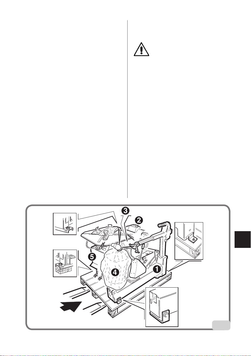
Before making the electrical and pneu-
matic hook-ups, make sure that the ma-
chine is congured as described below
(g.5):
- pedals A and B (if present) in fully de-
pressed position.
- column C vertical (not tilted).

Operator's manual M 824 45
EN
A
B
C
5
SAFETY
REGULATIONS
The equipment is intended for professional
use only.
WARNING
The machine may only be operated by
one operator at a time.
WARNING
Failure to observe the instructions and
danger warnings may result in serious in-
jury to operators and any other persons
in the vicinity. Do not start the machine
before reading and understanding all
the indications of danger, attention and
warning contained in this manual.
In order to operate the machine correctly, it
is necessary to be a qualied and authorised
operator, able to be trained and to know the
safety regulations. Operators are expressly
forbidden from using the machine under
the inuence of alcohol or drugs capable
of affecting physical and mental capacity.
The following conditions are essential:
- Be able to read and understand all the
information in this manual.
- Have a thorough knowledge of the capa-
bilities and features of this machine.
- Keep unauthorised persons well clear of
the area of operations.
- Make sure that the machine has been
installed in compliance with established
legislation and standards.
- Make sure that all machine operators are
suitable trained, that they are capable of
using the machine correctly and that they
are adequately supervised during their
work.
- Never leave nuts, bolts, tools or other
equipment on the machine to avoid the
risk that they could become entrapped
between moving parts during work.
- Do not touch power lines or the inside of
electric motors or other electrical equip-
ment until the power has been discon-
nected and locked out.
- Read this manual carefully and learn how
to use the machine correctly and safely.
- Always keep this operator's manual in a
place where it can be readily consulted
when working with the machine and
consult it whenever you are in need of
conrmation or explanations.
WARNING
Do not remove or deface the Warning,
Caution or Instruction decals. Replace
any missing or illegible decal. If one
or more decals have been detached or
damaged, replacements can be obtained
from your nearest dealer.
- When using and servicing the machine,
observe the standardised industrial ac-
cident prevention regulations for high

46 Operator's manual M 824
voltages.
- Any unauthorised alterations made to the
machine automatically release the manu-
facturer from any liability in the case of
damage or accidents attributable to such
alterations. Specically, tampering with or
removal of the machine safety devices is a
breach of the regulations relating to Safety
at Work.
WARNING
When operating or servicing the equip-
ment, tie back long hair and do not wear
loose-tting clothes, ties, necklaces,
rings or wristwatches which could be-
come tangled in moving parts.
TYRE CHANGER
DESCRIPTION
The M 824 is an electro-pneumatic tyre
changer.
The machine is compatible with any type
of drop-centre single-piece rims with the
dimensions and weights indicated in the
paragraph TECHNICAL DATA.
The sturdily constructed machine operates
with the wheel in a vertical position for bead
breaking and in a horizontal position for
mounting and demounting tyres. All func-
tions are controlled by the operator via ped-
als and hand-operated valves and levers.
TECHNICAL DATA
- Turntable clamping capacity
- internal clamping.............from 13"
- external clamping.....from 10" to 24"
- Rim width...............from 3.5" to 14"
- Max. tyre diameter .....1040 mm (41")
- Max. tyre width ...........360 mm (14")
- Bead breaker aperture: ........................
....................from 45 mm to 380 mm
- Bead breaking force .........................
...............15000 N (pressure 10 bar)
- Power supply voltage
- single-phase...115-230±10%Volt 50/60Hz
- three-phase...230-400±10%Volt 50/60Hz
- DV.......... 230±10%Volt 1ph 50/60Hz
- Operating pressure............8 - 10 bar
- Weight.......283 Kg (FS version 297 Kg)
- Noise levels in operating conditions ....
............................................≥ 70 dB (A)
OPTIONAL
ACCESSORIES
HELP power unit (8-11100288)
Model Motor rating kW Rotation
speed rpm
Torque
Nm
Weight of electric/
electronic part kg
M 824
400Volt/3ph 50Hz 0.75 8.5 1200 11.5
200/230Volt/3ph 60Hz 0.75 8.5 1200 11.5
200/230Volt/3ph 50Hz 0.75 8.5 1200 11.5
200/230Volt/1ph 50Hz 0.75 8.5 800 11.5
200/230Volt/1ph 60Hz 0.75 8.5 800 11.5
115Volt/1ph 60Hz 0.75 8.5 800 11.5
200/230Volt/1ph 50/60Hz DV 0.75 6-15 1200 10.2
115Volt/1ph 50/60Hz DV 0.75 6-15 1200 10.2
AIR MOTOR / 6.5 800 /

Operator's manual M 824 47
EN
Swinging arm (8-11100181)
Arm with bead lifting disc (8-11100183)
BSR Bridgestone wheels device
(8-11100182)
RUN FLAT device (8-11100194)
OVERALL
DIMENSIONS
A
B
D
E
C
1680 - 1950
880 - 1110
A
B
D
E
C
1120 - 1380
1320
1880
INTENDED
OPERATING
CONDITIONS
This tyre changer has been designed
exclusively for mounting and demounting
tyres, using the tools with which they are
equipped as described in this manual.
WARNING
Any use other than those described in
this manual is to be considered impro-
per and unreasonable.
The machine is equipped with an ination
system independent of all the other func-
tions described above.
Use the machine ination system with
extreme caution (read the INFLATION
section).
Figure 7 shows the operator's positions
during the various work phases:
A Bead breaking
B Tyre demounting and mounting
C Ination area.
7
C
A
B
WARNING
Column tilting must be performed from
work position C (g.7), keeping the
hands away from moving machine
parts.

48 Operator's manual M 824
WARNING
To stop the machine in an emergency:
- disconnect the power supply plug;
- isolate the compressed air supply
network by disconnecting the (quick-
coupling) shut-off valve (g. 7a).
7a
WARNING
When working with the machine it is
strongly recommended not to use equi-
pment or tools not manufactured by
SIMPESFAIP.
MAIN WORKING
ELEMENTS OF THE
MACHINE
WARNING
Get to know your machine: The best
way to prevent accidents and obtain
top performance from the machine is to
ensure that all operators know how the
machine works.
Learn the function and location of all
the controls.
Carefully check that all controls on the
machine are working properly.
The machine must be installed prop-
erly, operated correctly and serviced
regularly in order to prevent accidents
and injuries.
1 Vertical arm drive cylinder.
2 Locking handle
• Press lever A to lower the vertical arm,
release it to raise it.
• Hold down lever A and turn handle B to
lock the vertical arm.
• Turn handle B only to release the verti-
cal arm.
3 Vertical and horizontal arm (to position
the mounting/ demounting tool).
4 Mounting/ demounting tool (for mount-
ing and demounting tyre onto/from rim).
5 Tilting movable column.
6 Clamp gripper (secures the rim to the
turntable).
7 Turntable (rotary platform supporting
the wheel).
8 Movable column control pedal (5) (two-
position pedal for tilting the column
unit).
9 Clamp grippers (6) opening and closing
control pedal (three-position pedal for
opening/closing rim clamps).
10 Bead breaker control pedal (two-posi-
tion pedal to operate the bead breaking
shoe (13).
11 Turntable (7) rotation control pedal
(three-position pedal):
- Position 0 (stable) turntable
stationary.
- Pressed downwards (self-returns
to centre when released), rotate
clockwise.
- Lifted (self-returns to centre when
released), rotate anti-clockwise.
12 Ination pedal (two-position pedal on
STD model, three-position pedal on FS
version, used to inate tyre via Doyfe
connector (21)).
13 Bead breaker shoe (movable shoe to
detach the bead from the rim).
14 Deation button (button to remove the

Operator's manual M 824 49
EN
extra air inside the wheel).
15 Pressure gauge (reads the wheel
pressure).
16 Rim rest.
17 Safety relief valve (max. pressure 12
bar) (FS versions only).
18 Filter Regulator + Lubricator Unit (regu-
lates pressure, lters, removes humidity
of and lubricates the compressed air
supply).
19 Lube bottle.
20 Ination nozzles (air introduced through
these nozzles pushes the beads out-
ward to form a seal and permit ination)
(FS version only).
21 Air tank (FS version only).
22 Shoe guard.
23 Doyfe connector (ts onto tyre valve for
ination).
24 Bead lever
23
15
14
1
3
4
6
7
11
10
9
8
12
17
18
5
19
13
16
2
24
21
20
22

50 Operator's manual M 824
WARNING
For technical characteristics, warnings,
maintenance instructions and all other
information concerning the air tank,
consult the relative usage and mainte-
nance manual provided with the machi-
ne documentation.
Danger warning decals
Risk of crushing.
Never insert body parts
between the bead
breaking shoe, rim and
rim support.
When locking the rim on
the turntable, never in-
sert your hands between
the rim and the clamp
gripper.
NEVER stand behind the
machine.
NEVER insert your hands
between the wheel and
the head when lowering
the head.
BEAD BREAKING
WARNING
During this operation, noise levels
assessed at 85 dB(A) may occur. The-
refore we advise operators to wear
hearing protection devices.
Deciding from which side of
the wheel the tyre must be
demounted
Fig. 9
D
A
B
C9
A Narrow side - Side for mounting the
tyre.
B Rim well.
C Wheel.
D Wider side - You cannot mount tyres
from this side.
The two sides may be almost identical,
but only the narrow side serves for
tyre mounting and demounting.
Identify the side for tyre mounting and
make sure that this side is facing upward
when you install the tyre on the table top
(i.e. facing toward the mount/demount
head).
Special instructions
Alloy wheels
Some alloy wheels on the market have
minimal rim wells or are even completely
without rim wells (these wheels are not
DOT approved).

Operator's manual M 824 51
EN
Fig.9a
A
9a
A No rim well
DANGER
When working on this tyre type, the
tyre, the rim or both may get damaged,
with the risk of the tyre exploding due
to pressure causing serious injuries
or even death. When mounting tyres
on this type of wheel, use the utmost
caution.
European style high performance
wheels (asymmetrical curvature)
Some European wheels have very pro-
nounced curves on the rim edge, except
in the area of the valve hole. On this type
of wheel bead, breaking must be per-
formed in correspondence with the valve
hole and on the lower and upper side of
the wheel.
Fig.9b
A
BC
9b
A Valve hole
B Slight curvature
C Pronounced curvature
Wheels for Corvette, BMW, Lam-
borghini and other wheels with "Low
pressure indicator system"
Some types of high performance wheels
are equipped with a pressure transmit-
ter secured to the rim with a belt on the
side opposite the valve hole. On this type
of wheel bead breaking must be done
initially in correspondence with the valve
hole, on both sides of the rim.
Fig.9c
A
B
C
9c
A Valve hole
B Transmitter
C Attachment belt
Bead breaking
- Fully deate the tyre, removing the
valve.
- Adjust the opening of the bead breaking
shoe by turning the screw located on the
cylinder stem (g.10).
10

52 Operator's manual M 824
- Position the wheel as shown in g.11
and move the bead breaking shoe near
the rim edge.
IMPORTANT: During the bead breaking
operation, you are advised to keep the
turntable closed (clamp gripper towards
the centre) (g.11).
11
- Press the pedal (g.11) to operate the
bead breaker and detach the bead from
the rim.
Repeat this operation on the other side
of the wheel.
It may be necessary to break the bead
at several points to free it completely.
After detaching the beads, remove the
old balancing weights.
- Thoroughly lubricate the sides of the
tyre around the entire circumference of
the lower and upper bead to facilitate
demounting and avoid damaging the
beads (g.12).
12
CLAMPING THE
WHEEL
- Tip the column back, holding the button
in the locked position (g.13).
13
- Place the grippers in an open or closed
position (g.14).
- Place the wheel on the turntable (with
the narrow part of the rim structure fac-
ing upwards), push lightly downwards
and use the control pedal to clamp the

Operator's manual M 824 53
EN
10”-20” 13”-23”
14”-24” min 17”
14

54 Operator's manual M 824
wheel into position (g.14a).
14a
- Move the column forward (g.15).
15
DEMOUNTING
- Release the lock button, releasing
both the vertical and horizontals arm
(g 15a), and position the mounting/
demounting device correctly against the
rim edge (g.16).
IMPORTANT: pressing the button locks
both the vertical and horizontal arms
simultaneously.
This space between the rim and the verti-
cal slide will be maintained for as long as
the button is in the locking position.
The operator can tilt the tower freely (e.g..
when demounting wheels of the same size)
without repositioning the vertical slide.
16
B
A
B
A
17
- Fit the bead lifter lever (Fig. 18) between
the mounting head and the tyre bead.
18

Operator's manual M 824 55
EN
- Repeat the same procedure to break the
other bead (g. 21).
21
- Move
the column forward
in “not work-
ing position”, then remove the tyre from
the wheel.
MOUNTING
WARNING
Always check that the tyre size is
compatible with the rim size before
mounting.
- Before you start with tyre mounting op-
erations, lubricate the beads (g.22).
Lubricated beads require less force to
mount/seat and are protected against
torsional damage.
22
ATTENTION:
When working with alloy
wheels or wheels with easily damaged
paint, we recommend tting the spe-
cic plastic protectors on the lever.
WARNING
Grip the bead lifting tool rmly during use.
- Lift the top bead over the front of the
demounting head (g. 19) and push part
of the top bead into the rim well by press-
ing downwards on the side wall from the
side opposite the head.
19
- Start the demounting procedure by tap-
ping the pedal gently (g. 20).
20
- Rotate the wheel by one complete turn,
and press onto the tyre by hand on the
side opposite the head to ensure that the
entire bead is pushed into the rim wheel.
ATTENTION: If the tyre has an inner
tube, move the arm out of the working
position then remove the inner tube.

56 Operator's manual M 824
- Place the tyre on top of the wheel and
move the column into the working posi-
tion.
- Place the bottom bead under the front
of the head.
- Press the turntable control pedal to rotate
clockwise and mount the bead. Use the
rim well space, pressing onto the right
hand sidewall to reduce torsion on the
bead as the wheel rotates (g. 23).
23
- After mounting the bottom bead, repeat
the same procedure for the top bead
(Fig. 24).
24
- Move
the column forward
in “not working
position”, then remove the wheel from
the tyre changer.
APPROVED UHP
AND RUN FLAT
TYRE DEMOUNTING
AND MOUNTING
PROCEDURE
For a detailed description of the UHP and
RUN FLAT tyre mounting/demounting
procedure, please refer to the instruc-
tions in the manual prepared by WDK
(German Tyre Industry Association).
INFLATION
WARNING
Ination is a notoriously hazardous
operation. It must be carried out in ac-
cordance with the instructions provided
below.
WARNING
Noise levels may reach 85 dB(A) during
this procedure. Therefore we advise
operators to wear hearing protection
devices.
WARNING
During bead insertion and ination, the
use of goggles and ear protectors is
recommended.
DANGER
Although it does have a pressure li-
miting function, the machine cannot
guarantee sufcient protection if the
tyre explodes during ination. Failure to
comply with the instructions below will
render tyre ination dangerous.

Operator's manual M 824 57
EN
- Connect the Doyfe inator chuck on the
air hose to the valve stem.
Inate the tyre by operating the proper
pedal (Fig. 26) at short intervals; check
the pressure gauge (1, Fig. 25) frequently
to make sure that the pressure NEVER
exceeds the maximum pressure specied
by the tyre manufacturer.
26
Inating tubeless tyres
(FS versions only)
WARNING
Before carrying out the operations des-
cribed below, always make sure that
there is no dirt, dust or other impurities
on the jaws near the air outlet holes.
- Make sure that the wheel is secured to
the table top with inside clamping (Fig.
27).
27
DANGER
NEVER exceed the pressure value re-
commended by the tyre manufacturer.
Tyres may explode if inated beyond
these limits or their structure may be
damaged seriously although not visibly
at that moment. KEEP YOUR HANDS
AND BODY AWAY FROM THE TYRE
DURING INFLATION. Avoid being dis-
tracted during this operation and check
the tyre pressure often to prevent the
tyre from being excessively inated. A
bursting tyre can cause serious inju-
ries or even death.
Inating procedure
The machine has a pedal for inating the
tyre and a pressure gauge for reading the
tyre pressure.
- Release the wheel from the sliding
clamps on the table top.
- Bring the horizontal arm to the fully ex-
tended position.
- Lower the vertical rod until it touches the
rim.
- Lock the horizontal arm and the vertical
rod in the positions described above g.
25.
25
1
Table of contents
Other HPA-Faip Tyre Changer manuals
Popular Tyre Changer manuals by other brands

AME Intl.
AME Intl. 71025 instruction manual

WERTHER INTERNATIONAL
WERTHER INTERNATIONAL TITANIUM 200/22 Instruction and maintenance manual

Nussbaum
Nussbaum TC 410 instruction manual

Ranger
Ranger R30XLT Installation and operation manual

Actia Muller
Actia Muller BEM 4886 Installation, operation and maintenance guide

Hunter
Hunter TC39 Series Operation instructions