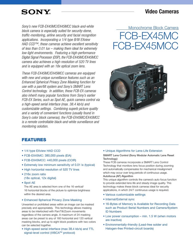
Atmos Cam 21 User manual

2018-08 Index 09
GA1GB.150401.0
Operating Instructions
ATMOS®Cam 21 / 31
English

2
Further information, accessories, consumables and spare parts are available from:
ATMOS
MedizinTechnik GmbH & Co. KG
Ludwig-Kegel-Straße 16
79853 Lenzkirch
Germany
Phone +49 7653 689-0
Fax: +49 7653 689-190
+49 7653 689-292 (Service Centre)
www.atmosmed.de

3
Table of contents
1.0 Introduction.....................................................4
1.1 Notes on operating instructions ...................................... 4
1.2 Explanation of pictures and symbols .................................. 5
1.3 Intended use ...................................................... 6
1.4 Function .......................................................... 6
2.0 Hints for your safety .............................................7
3.0 Setting up and starting up ........................................9
3.1 Scope of delivery ................................................... 9
3.2 Connections and operating elements ................................. 9
3.3 Digital monitor outlets ............................................. 12
3.4 Setup............................................................ 12
3.5 Fitting the holder for the camera head
(not applicable for ATMOS® Roadster) ................................ 12
3.6 Start up .......................................................... 14
4.0 Operation ......................................................16
4.1 On/Oswitch.................................................... 16
4.2 Adjustapplicationproles .......................................... 16
4.3 Camera head ..................................................... 17
4.4 Images-storage mode.............................................. 18
4.5 SD card (Cam 31 / DV / Data)........................................ 19
4.6 LED light source (option) ........................................... 20
4.7 Manual white balance ............................................. 21
5.0 Cleaning and care ...............................................22
5.1 General information on cleaning and disinfection...................... 22
5.2 Control unit ...................................................... 22
5.3 Camera head with video adapter .................................... 22
5.4 Chemical disinfection .............................................. 23
5.5 Surface disinfectants .............................................. 23
6.0 Maintenance and Service ........................................24
6.1 Fuse exchange .................................................... 24
6.2 Period tests ...................................................... 24
6.3 Pixel error correction .............................................. 25
6.4 Sending in the device .............................................. 25
7.0 Troubleshooting ................................................26
8.0 Accessories and spare parts......................................27
8.1 Accessories....................................................... 27
8.2 Options .......................................................... 30
8.3 Spare parts....................................................... 30
9.0 Technical data ..................................................31
10.0 Check-up / Disposal .............................................33
10.1 Checking ATMOS devices ........................................... 33
10.2 Disposal ......................................................... 33
11.0 Arrangement ...................................................34
12.0 Notes on EMC ..................................................35
13.0 For your notes ..................................................39

4Introduction
1.0 Introduction
Information on the device versions
Compared to the ATMOS® Cam 21, the ATMOS® Cam 31 has an additional image
memory. The DV versions also have a USB-connection to conduct the video signal to the
PC.
ATMOS®Cam 31 Cam 21 DV Cam 31 DV Cam 31 DV Data
Image memory: -
Outputs:
FBAS
S-Video
HDMI
Digital Video Streaming:
USB -
Display of symbols ---
SD card -
Audio in / out -
1.1 Notes on operating instructions
In the following all device versions, as well as all modules and table-top devices are
named ATMOS® Cam 21/31.
These operating instructions contain important notes on how to operate
the ATMOS®Cam21/31safely,correctlyandeectively. Their reading
helps to avoid risks, and also to reduce repair costs and down-times. This
increases, amongst other things, the reliability and service-life of the device.
These operating instructions serve not only for new operating personnel to be
instructed in its use, but also for use as a reference manual. Reprints (also in
extracts) only with permission in written form by ATMOS.
These operating instructions must always be kept available near the
device.
Care and period tests in conjunction with professional execution provide
for operational safety and readiness for use of your ATMOS®Cam 21 / 31
and are therefore a must besides regular cleaning.
Repair work and period tests may only be carried out by expert personnel
authorised by ATMOS. By applying only original spare parts you will have the
guarantee that operational safety, readiness for work and the value of your
ATMOS® Cam 21 / 31 will be preserved.
The product ATMOS®Cam 21 / 31 bears CE marking CE according to the
EC Directive of the council for medical products 93/42/EEC and meets the
basic requirements of Appendix I of the directive.
The product ATMOS®Cam 21 / 31 complies with all applicable
requirements of the directive 2011/65/EC restricting the use of certain
hazardous substances in electrical and electronic equipment (“RoHS”).
The declaration of conformity and our general standard terms and conditions
can be obtained on our website at www.atmosmed.com.
ThequalitymanagementsystemappliedatATMOShasbeencertied
according to international standards EN ISO 13485.
Prior to start-up please peruse chapter 2.0 „For your safety“, in order to be
prepared for any possible dangerous situations.

5
Introduction
1.2 Explanation of pictures and symbols
Icons and symbols in the operating instructions
The symbol warns you against
dangerous situations Always pay
attention to the instructions in this
manual.
This symbol indicates situations
by which your device could be
damaged.
TIPP Useful information on the handling of
the device.
Engage,checkcorrectt
Please press where dot indicates Move, plug... in this direction
Activate the optional foot switch Turn, shift... in this direction
Check Replace
Shortcuts on the device
Fuse according to IEC 417/5016,
DIN 30600/0186
Signal Input, Y/C, FBAS, Audio
Application part type BF Signal Output, Y/C, FBAS, Audio,
USB
Potential equalisation Interlink / Data
Ground wire connection Foot switch
~Alternating current On (feed-in, power connection)
Observe operating instructions O(feed-in,powerconnection)
Follow operating instructions
(blue)
Control keys ATMOS® Cam 21 / 31
Endoscope
Usage: Examination of nose and
ears
• Hysteroscopy
Typ. ø:2.7 and 4 mm respectively
Typ. angles: 0°, 30°, 45°, 70°
Laryngoscope / Endoscope
Usage: Laryngeal examinations
• Hysteroscopy
Typ. ø : 10 mm
Typ. angles: 70°, 90°
Flexible Endoscope /
Hysteroscope
Usage: Nose, throat, larynx
examinations
• Hysteroscopy
Microscope/ Colposcope
Usage: Examination of ears
• Colposcopy
Xenon light source
Typical: 180 W resp. 300 W
Colour temperature: 5600-5800 K
Halogen light source
Typical: 150 resp. 250 W
Colour temperature: 3200 K
Stroboscopeashlightsource
(ENT)
Usage: Laryngo-stroboscopy
Colour temperature: 5800 K
LED light source
Typical: 2 W (e.g. ATMOS LED
light source and LED headlight
-please see accessories in chapter
8.0).

6Introduction
1.3 Intended use
Name: ATMOS® Cam 21 / 31
Main functions: The ATMOS® Cam 21 / 31 is an ENT camera for displaying the
examination image on a screen or a PC.
Medical indications /
application:
The camera is intended to be connected to common
ENT-endoscopes with a standard ocular and to a microscope
with a beam splitter.
Specification of the
main function:
Camera head: High-definition CCD-camera with a high
sensivity to light and large depth of field, connection to
endoscopes, an easy changing of endoscopes, control
possibility for digital zoom, a simple focusing possibility,
automatic white balance
Control unit: Simplest camera setting, selection of the optical
instrument, selection of the type of light, supply interface for
LED light source, 2 analogue (1 x Y/C (S-Video) and 1x FBAS
(Composite)) and 2 digital (2 x HDMI) monitor outputs.
Application organ: Ear, nose, throat
Application time: Temporarily (max. 60 minutes)
Application site: In clinics and practices for ENT doctors and phoniatricians. The
camera may only be operated and applied by medically trained
staff.
Contraindications: Not intended for use in explosion-hazardous areas.
The product is: X active□not active
Sterility: Not necessary
Single-use product /
reprocessing:
No single use product
1.4 Function
The ATMOS® Cam 21 / 31 consists of a camera head and the control unit. Both elements
are connected detachably via a cable of 3 m length.
The camera head includes a 1/3“ CCD colour image sensor with microlenses for
connection to commercially available endoscopes with standard ocular objectives.
Only applicable for ATMOS®Cam 21 / 31 DV:
For Windows 7 and MAC OS 10.x the camera can be directly connected to a computer
due to the USB interface and the audio-in and therefore a transmission in digital format
is possible. Therefore the camera can be connected to PCs with USB, without any
additional hardware.
Starting from Windows 8 a SD-Grabber must be used.

7
Hints for your safety
2.0 Hints for your safety
The safety of the ATMOS@Cam 21 / 31 complies with all the recognized rules of
technology and the guidelines of the Medical Products Law.
Read and follow the safety instructions carefully before using the product.
General safety information
The ATMOS® Cam 21 / 31 is:
• designed in line with IEC 60601-1 / EN 60601-1.
• assigned to VDE safety class I
• assigned to class I of the German law on medical products.
The ATMOS® Cam 21 / 31 fully complies with the electromagnetic immunity
requirements of standard IEC 60601-1-2 / EN 60601-1-2 "Electromagnetic compatibility
– Medical Electrical Equipment".
Pay also attention to the safety information of the attached devices / parts.
ATMOS is not liable for personal injury and damage to property if
• no original ATMOS parts are being used,
• the advice for use in these operating instructions is not being observed,
• assembly, new settings, alterations, extensions and repairs have been carried out by
personnel not authorised by ATMOS.
Please check the delivery on completeness and intactness.
TheATMOS®Cam21/31maybeusedinsupervisedoperationbyqualiedpersonnel
only which has been authorised by ATMOS and which has been trained for operating
the appliance (IEC 60601-1/EN 60601-1).
Pay also attention to the safety information of the attached devices / parts as well as to
the safety informations in the following chapters.
For the camera head only extension cables with maximum 2 m length may be used.
Incaseofaninsucientilluminationtheexaminationhastobecancelledrespectivelya
brighter light source has to be used.
The warranty will be rendered invalid in case of damages caused due to the utilization
of accessories or consumables which are not approved by ATMOS for use with this unit.
Clean and disinfect the camera in regular intervalls (peruse chapter 5.0).
Dangers for users, patients and third parties
Protect yourself against an electric shock!
• Todisconnectthedevicefromthemainssupply,rstremovetheplugfromthewall
outlet. Disconnect the connection line on the device afterwards only.
• Priortocleaning,switchothedeviceandseparateitfromthemainssupplyresp.
from other devices.
• Never touch the device’s interfaces and the patient at the same time!
• Do not touch the cables or plugs wit wet hands!
• Check the device and connection lines for defects prior to the use of the device.
• Damaged cables must be replaced!
Danger of explosion!
• The ATMOS® Cam 21 / 31 is not designed for the use in medical areas with an
explosion hazard or which are oxygenated. Explosion-hazardous areas may be
causedbytheuseofammableanaesthetics,skincleansingproductsandskin
disinfectants.

8Hints for your safety
Damage to the device
Priortorststartingup,checkwhetherthemainsvoltagespeciedonthetypeplate
matches the local mains voltage.
For mains supply, only use the power cable supplied (or an equivalent one).
The device may only be connected to a properly installed protective contact socket.
A medical insulating transformer with earth leakage monitor or any similar safety
system acc. to EN 60601-1 is required, if several devices are connected over one
common power supply. The transformer must correspond to the power consumption
of all the devices to be connected.
Payattentiontotheambientconditionsspeciedinchapter9.0.
The ATMOS® Cam 21 / 31 may not be operated with units not complying with the
requirements of standard EN 60601-1 "Medical Electrical Equipment" and EN 60601-1-2
"Electromagnetic compatibility (Medical Electrical Equipment)".
Checkproperassignmentwhenassemblingcountry-specicconnections:
green/yellow: non-fused earth conductor, blue: neutral conductor, black or brown:
phase
Do only use the recommended accessories and compounds.
Protect the device against direct solar radiation and keep it away from heaters.
The lens of the focusing optic should be protected against mechanical contact.

9
Setting up and starting up
3.0 Setting up and starting up
3.1 Scope of delivery
ATMOS®Cam 21
DV
Cam 31 Cam 31
DV
Cam 31 DV
Data
Camera housing
Holder for camera head
Camera head
Foot switch for image storage
Data transfer cable
Audio cable for stroboscope audio
channel incl. adapter plug
S-Video cable
Cable and adapter HDMI to DVI
USB cable
SD card
Operating Instructions
3.2 Connections and operating elements
Patient at least 1.5 m
from video components
which do not correspond
to EN-60601-1
Non-medical product
For guaranteeing shortest connecting paths, the video components (recorder, printer,
monitor, etc.) should be positioned near to the ATMOS® Cam 21 / 31.
Please pay attention to operate all video components from one mains distributor.
All additional equipment which is connected to the analogue and digital interfaces of
the device must meet the requirements of relevant EN specifications (for inst. EN 60950
for data processing equipment and EN 60601-1 for electrical medical equipment). In
addition, configurations must satisfy system specification EN 60601-1-1: 2001. When
additional equipment is connected to the signal input or signal output section on the
device, the person carrying out the connection is deamed „a system configuration
operator“ and as such is responsible for meeting the requirements of system
specification EN 60601-1-1: 2001. For answers to additional questions, please contact
your local specialist supplier or the ATMOS Technical Service.
Please note that the use of components other than listed in chapter 8.0 may have a
negativeinuenceontheimagequalityduetoickeringandimagedropouts.

10 Setting up and starting up
Forefront
A
B
1 2
AButtons for selecting application part and light source
BMainson/oswitch
1Connection for camera head
2Connection for LED light source
Rear side of the Cam 31
5
7 8 9 10 11 12
16 17 18
5SD card
7, 8Connection for HDMI video
output
9Connection for video output (Y/C)
10 Connection for video output
(FBAS)
11 Connection for rear side video
input (Y/C)
12 Connection for rear side video
input (FBAS)
16 Nut for mains supply
17 Connection for potential
equalization
18 Connection for foot switch

11
Setting up and starting up
Rear side of the Cam 21 DV / 31 DV
3 5
7 8 9 10 11 12
13 14 15
16 17 18
3USB
5SD card
7, 8Connection for HDMI video
output
9Connection for video output (Y/C)
10 Connection for video output
(FBAS)
11 Connection for rear side video
input (Y/C)
12 Connection for rear side video
input (FBAS)
13 Audio output (line level)
14 Audio input
15 Line-In M/C in
16 Nut for mains supply
17 Connection for potential
equalization
18 Connection for foot switch
Rear side of the Cam 31 DV Data
43 5
7 8 9 10 11 12
13 14 15
16 17 18
3USB
4Data gateway
5SD card
7, 8Connection for HDMI video
output
9Connection for video output (Y/C)
10 Connection for video output
(FBAS)
11 Connection for rear side video
input (Y/C)
12 Connection for rear side video
input (FBAS)
13 Audio output (line level)
14 Audio input
15 Line-In M/C in
16 Nut for mains supply
17 Connection for potential
equalization
18 Connection for foot switch

12 Setting up and starting up
3.3 Digital monitor outlets
The cameras ATMOS® Cam 31 DV and ATMOS® Cam 21 DV feature a digital monitor
output with SXGA signal.
The resolution of the monitor has to be at least 640 x 480 pixel.
Please note that only the digital or analogue video outputs can be activated.
3.4 Setup
Possible settings:
• Video-input
• Audio-input
• Date and time
1. Connecting the inputs, e.g.
Video input Y/C
Video input FBAS
2.
3. Initialization phase
when all the LEDs are illuminated:
Press the desired application
prole.
4.
The LED key
ashes.
5.1 Setting the video and
audio:
• thesameapplicationprole
key: select one of the inputs.
• anotherapplicationprole
key: Save the input and go to
the next setting.
5.2 Video input
• Video input Y/C
• Video input FBS
• Standard-camera head
5.3. Audio input
• Microphone-In
• Line-In
6.1 Setting the date and time:
+
-(only for year!)
• otherapplicationprolekeys:
Save the input and go to the next
setting
6.2 Setting the date and
time:
• Year
• Month
• Day
• Hour
• Minute
7.
a Using the cam
• Select any function.
bSetting other optics:
to 1.
3.5 Fitting the holder for the camera head (not applicable for ATMOS®

14 Setting up and starting up
3.6 Start up
Please pay attention, just to switch on the devices after they have been completely
wired.
If required, analogue peripheral video equipment (monitor, video printer, etc) must
be adjusted to NTSC video norm. For further details please look at the corresponding
operating instructions.
1. 2. Optional 3. Valid for Cam 21 / 31 DV
4.
Y/C / S-VHS
FBAS (composite) / VHS
HDMI / DVI
5. Valid for Cam 31 / DV / Data 6.

15
Setting up and starting up
3.6.1 Connection diagram ATMOS® Cam 21 / 31 Data
ATMOS® Cam 31 DV DATA
digital
Computer
• to Windows 7
USB Streaming
ATMOSoft external microphone
REF 507.1806.0
S-video source (Y/C)
e.g. ATMOS® i View (microscope)
FBAS-videosource
e.g. ATMOS® Scope
valid for:
CAM 31
CAM 31 DV
CAM 31 DV DATA
analogue
ATMOS® Strobo 21 LED
(valid for cameras “DV“ and
“Data“)
ATMOS® Strobo 21 LED
(valid for cameras “Data“)
Cable and adapter for monitor:
Digital
HDMI/DVI-adapter REF 507.5451.0
HDMI-cable REF 008.0913.0
Analogue
Cable video S-VH (Y/C) REF 008.0635.0
Cable video FBAS REF 008.0844.0

16 Operation
4.0 Operation
4.1 On / O switch
Initialization phase: All lights are on.
Standard
camera head
or
Last selected
mode
wait at least 10 sec.
4.2 Adjust application proles
1.
select the connected instrument
2.
select type of light source
Automaticcongurationoftheoptimumcameraparameter.
Endoscope Xenon light
source
Laryngoscope/
Endoscope
Halogen light
source
Flexible
Endoscope /
ATMOS Scope
Hysteroscope
Stroboscope
ashlightsource
(ENT)
Microscope /
Colposcope LED light source

17
Operation
4.3 Camera head
4.3.1 Inserting / replacing the application part
1.
2.
click
4.3.2 Focussing / image denition
Pre-adjustment
During the examination
4.3.3 Digital zoom
Amplicationandminiaturisationofexaminationimage.
Zoom steps: 1.0 x / 1.5 x / 2.0 x / 4.0 x.

18 Operation
4.4 Images-storage mode
Only applicable for ATMOS® Cam 31 / DV / DATA.
• Live mode: Displays live images of the examination. White balance and zoom are
possible.
• Memory mode:
- 1-image memory mode: One examination picture is saved on the SD card and
displayed in full screen size.
- 4-images memory mode: Four examination pictures or up to three examination
pictures and the live picture are displayed simultaneously.
1-image memory mode
When you insert an SD card the picture will be saved.
1. Live
live
2.
short
3. 1-image memory
still
no SD-Card
4-images memory mode
When you insert an SD card every picture will be saved.
1. Live
live
2.
2 - 3 sec.
3. 4-images memory mode : live
live
4.
short
5. 4-image memory
1live
6.
short
7. 4-image memory
live
12
8.
...
9. 4-images memory:
12
3 4
10.
2-3 sec.
11. Live
live

19
Operation
4.5 SD card (Cam 31 / DV / Data)
The SD card cannot be used if the ATMOS® Cam 31 / DV / Data is integrated in a
treatment unit (e.g. ATMOS® S 61 Servant).
If necessary remove the memory protection from the SD card and insert it with the
printed side up. Pay attention to the operating instructions of the SD card.
You can insert and remove the SD card in the live mode. Make sure you do not press
any other key.
If there are a lot of pictures on the memory card then storage takes longer.
Save
1. Live
live
2.
short
3. SD card
Pic stored still
4.
short
5. Live
live
Display
Theimagewiththemostrecentdatewillbeshownrst.
From the most recent picture via +return to the Live-Mode.
1. Live
live
2.
+approx. 3 sec.
3. SD card
P -01
4.
+1recent date
-2older date
5.
-approx. 3 sec.
6. Live
live
TIPP

20 Operation
4.6 LED light source (option)
1. 2. 3.
click
4.
Other manuals for Cam 21
1
This manual suits for next models
4
Table of contents

