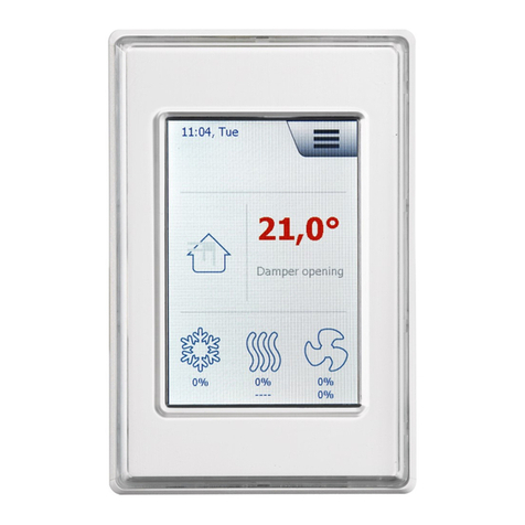
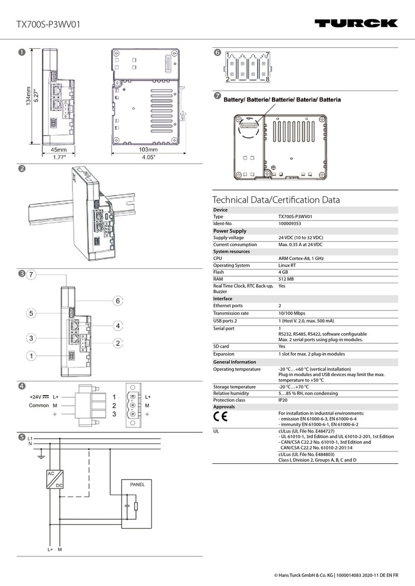
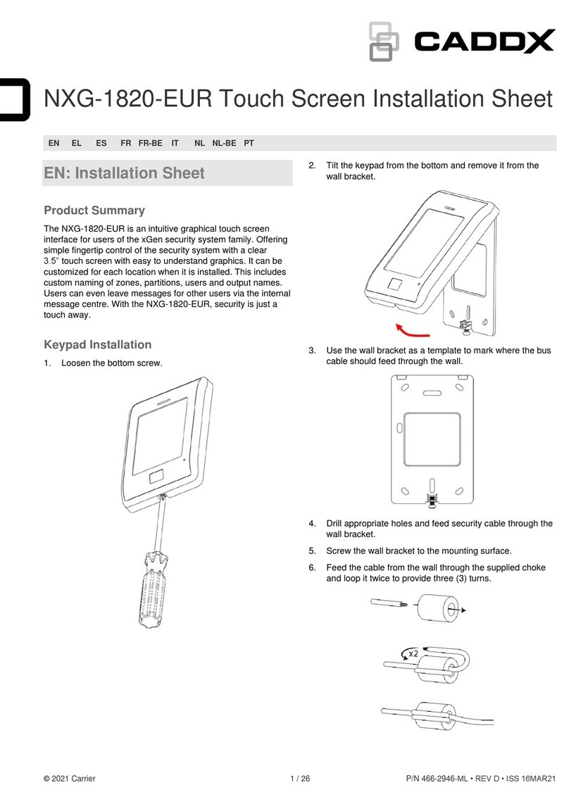
Atmos ARU30 User manual

ATMOS
ATMOS
ARU30
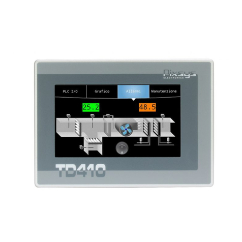
Pokojová jednotka s dotykovým displejem
Room unit with touch screen
Raumgerät mit Touchscreen
NÁVOD K OBSLUZE - INSTRUCTION MANUAL - BEDIENUNGSANLEITUNG
POPIS / DESCRIPTION / BESCHREIBUNG:
CZ - Pokojová jednotka ARU30 je určena pro intuitivní ovládání topného okruhu, informování o nastavených parametrech a režimech, k měření pokojové teploty
a vlhkosti. Pomocí dotykového displeje umožňuje provádět změny požadované teploty v místnosti v závislosti na čase, provádět změny režimů s využitím
přednastavených funkcí a komunikovat s regulací ATMOS ACD 03/04. Pokojová jednotka ARU30 umožňuje elektronické regulaci ACD03/04 optimalizovat
vytápění objektu (teplotu vody pro daný topný okruh).
-----
EN - ARU30 room unit is designed for intuitive control of the heating circuit, provision of information on the set parameters and modes, and for the measurement
of room temperature and humidity. The use of the touch screen allows you to change the required room temperature in dependence on time, change modes
using preset functions and communicate with the ATMOS ACD 03/04 controller. ARU30 room unit enables the ACD03/04 electronic controller to optimize heating
of the building (water temperature for the relevant heating circuit).
-----
DE - Das Raumgerät ARU30 dient zur einfachen Regelung des Heizkreises, zur Anzeige der eingestellten Parameter und Betriebsarten sowie zur Messung
der Raumtemperatur und -feuchtigkeit geeignet. Über den Touchscreen können Sie die Raumtemperatur zeitabhängig ändern, Betriebsarten unter Nutzung
von voreingestellten Funktionen ändern und mit dem Regelgerät ATMOS ACD 03/04 kommunizieren. Das Raumgerät ARU30 ermöglicht, die Heizung des
Gebäudes bzw. das Wassertemperatur für den entsprechenden Heizkreis durch das elektronische Regelgerät ACD03/04 zu optimieren.
Technické údaje pokojové jednotky / Technical Data of the Room Unit / Technische Daten der Raumgerät
Napájecí napětí / Supply voltage / Versorgungsspannung: 12 VDC (6,0 VDC ÷ 14,0 VDC)
Max. odběr / Max. consumption / Max. Leistungsaufnahme: 180 mA při 8 V (250 mA / 6 V, 120 mA / 12 V)
Elektrické krytí / Electrical parts protection / Elektrische Schutzart: IP20
Ochrana před úrazem el. proudem / Protection against electric shock / Schutzklasse:
III
(napájení bezpečným malým napětím) / (safe low voltage supply) /(Versorgung mit Sicherheitskleinspannung)
Připojovací svorky / Connecting terminals / Anschlussklemmen: vodič průřezu 0,2 až 0,75 mm
2
/ electric wires of
the 0.2 to 0.75 mm
2
cross-section / Kabelquerschnitt 0,2 bis 0,75 mm
2
Komunikační linka / Communication line / Kommunikationslinie: ATMOSNET - délka kabelu max. 200 m
ATMOSNET - cable length max. 200 m
ATMOSNET - Kabellänge max. 200 m
Rozměry (ŠxVxH) / Dimensions (WxHxD) / Abmessungen (BxHxT): 124x84x27 mm
Prostředí / Environment / Umgebung
Prostory / Rooms / Räume: vnitřní / indoor / innere
Provozní teplota / Operational temperature / Betriebstemperatur: -20 ÷ +50 °C
Skladovací teplota / Storage temperature / Lagerungstemperatur: -20 ÷ +50 °C
Vlhkost / Humidity / Feuchtigkeit: 0 až 90 % relativní vlhkosti, nekondenzující / 0 to 90 % relative humidity,
non-condensing / 0 bis 90 % relativer, ohne Kondensation
MONTÁŽ / ASSEMBLY / MONTAGE:
CZ - Pokojová jednotka ARU30 je určena k pevnému namontování na stěnu dvěma šrouby (4x35) a
hmoždinkami (6x30) nebo na instalační krabičku. Přístup k montážním otvorům a k připojovací svorkovnici je
po sejmutí přední části krabičky. Je potřeba dbát zvýšené opatrnosti, aby nedošlo k mechanickému poškození
či znečištění propojovacích kontaktů. Je potřeba dbát na rovinnost podkladu, aby nedošlo ke zkroucení zadní
stěny krabičky a špatnému kontaktu mezi deskou svorkovnice a elektronikou.
Otevření krabičky provedeme rukou, vyvinutím tlaku prstů (zmáčknutím) zespodu uprostřed.
POZOR - Pracovník provádějící montáž a opravy elektronické regulace ACD03/04 a příslušenství
musí být řádně proškolen a odborně způsobilý. Veškeré práce je nutné provádět dle platných norem
a bezpečnostních předpisů!
-----
EN - The ARU30 room unit is intended for xing assembly on a wall by means of two screws (4x35) and dowels
(6x30) or on an installation box. The access to assembly openings and to the connection block is possible after
removing the front part of the box. It is necessary to pay attention to avoid mechanical damage or contamination
of the connecting contacts. It is necessary to pay attention to the atness of the base layer to avoid twisting the
back side of the box and poor contact between the terminal board and electronics.
The box can be opened by hand, by applying nger pressure (by pressing) in the middle of the bottom side.
ATTENTION - The person performing the installation and repair of the ACD03/04 electronic controller
and accessories must be properly trained and professionally qualied. All work must be performed in
accordance with valid standards and safety regulations!
1

DE - Das Raumgerät ARU30 ist zur xen Wandmontage mittels zwei Schrauben (4x35) und Dübeln (6x30) oder in Installationsbox bestimmt. Der Zugang zum
Montageönungen und der Anschlussleiste wird durch das Abnehmen der Vorderseite der Box ermöglicht. Es ist besonders sorgfältig darauf zu achten, dass
die Verbindungskontakte weder verschmutzt noch mechanisch beschädigt werden. Der Untergrund muss eben sein, damit die Hinterwand der Dose nicht
zusammenbricht und es keinen Kurzschluss zwischen der Klemmenplatte und der Elektronik gibt.
Die Dose können Sie von Hand so önen, dass Sie von unten in der Mitte mit Fingern drücken.
ACHTUNG - Die Montage des elektronischen Regelgeräts ACD03/04 samt Zubehör darf nur durch geschultes Fachpersonal durchgeführt werden!
Sämtliche Arbeiten sind gemäß den geltenden Normen und Sicherheitsvorschriften durchzuführen!
MÍSTO MONTÁŽE / PLACE OF THE ASSEMBLY / MONTAGEORT:
CZ - Nástěnnou jednotku je třeba umístit ve výšce přibližně 1.2 až 1.5 m na neutrální místo, tzn. na referenční místo pro všechny místnosti (topný okruh).
K umístění je vhodné zvolit některou vnitřní mezistěnu nejchladnější místnosti denního pobytu.
-----
EN - The wall unit must be placed at a height of approximately 1.2 to 1.5 m in a neutral place, i.e. to a reference point for all rooms (heating circuit).
It is advisable to choose one of the inner partition walls of the coldest room of the stay during the day.
-----
DE - Die montage der Wandeinheit muss in ca. 1,2 - 1,5m Höhe im jeweiligen Referenzraum des Heizkreises erfolgen.
Zur Lokalisierung wird es geeignet, eine innere Zwischenwand des kühlsten Zimmers für alltägliche Verbleib auszuwählen.
CZ - Nástěnná jednotka nesmí být umístěna na těchto místech
• na místech s přímým slunečním zářením (zohlednění sezónních výkyvů)
• v blízkosti přístrojů vyvíjejících teplo jako jsou televizory, chladničky, nástěnné lampy, topná tělesa apod.
• na stěnách, za nimiž jsou vedeny trubky topení popřípadě teplé vody nebo kde jsou vyhřívané komíny
• na vnějších stěnách
• v rozích výklenků stěn, regálů nebo za závěsy (kvůli nedostatečné cirkulaci vzduchu)
• v blízkosti dveří k nevytápěným místnostem (kvůli vlivu cizího chladu)
-----
EN - The wall unit must not be situated at following points
• in places with direct sunlight (taking into account seasonal changes)
• close to heat - generating devices such as TVs, refrigerators, wall lamps, radiators, etc.
• on the walls behind which heating pipelines or hot water pipelines are situated or if there are heated chimneys
• on external walls
• in the corners of wall niches, racks or behind curtains (because of the insucient air circulation)
• close to doors to unheated rooms (due to the inuence of cold temperature)
-----
DE - Die Wandeinheit darf nicht an folgenden Stellen platziert werden
• an Stellen mit direkter Sonneneinstrahlung (die Berücksichtigung der Jahreszeitabweichungen)
• in der Nähe von Geräten, die Wärme entwickeln, z.B. Fernseher, Kühlschränke, Wandlampen, Heizkörper, usw.
• an Wänden, hinter denen Heizung- bzw. Warmwasser-Leitungen geführt sind oder wo sich erwärmte Schornsteine benden
• an äußeren Wänden
• in Ecken oder Nischen, Regalen oder Vorhängen (wegen mangelnder Luftzirkulation)
• in der Nähe der Türen zu unbeheizten Räumen (wegen Einwirkungen von Zugluft)
ELEKTRICKÉ PŘIPOJENÍ / ELECTRICAL CONNECTION / ELEKTRISCHER ANSCHLUSS:
CZ - Pro připojení použijeme stíněný čtyřžilový kabel (dva kroucené (twistované) páry) s průřezem 0,2 až 0,75 mm2. Jeden pár slouží k napájení, druhý
pár k přenosu dat. Stínění připojíme na straně elektronické regulace ACD03/ACD04 k ochranné svorce PE. Na straně pokojové jednotky necháme stínění
nezapojené. Svorky GND jsou na plošném spoji navzájem propojené.
Připojovací kabel doporučujeme vést izolovaně od vodičů 230V a jiných silových vedení (alespoň 5 cm).
Při delším vedení dbáme na to, aby měly napájecí vodiče dostatečný průřez, aby nedocházelo k velkému úbytku napájecího napětí.
Tabulka předpokládá celkový odpor napájecího vodiče tam a zpět 14 Ω.
Pokud by byl kabel využit k napájení dalších zařízení, je nutné tuto skutečnost zohlednit a počítat s celkovým příkonem!
Pokojová jednotka je standardně napájena přímo z regulace ACD03/ACD04 (čtyřlinka).
POZOR - Přímo z regulace ADC03/04 je možné napájet pouze jednu pokojovou jednotku ARU30 společně až se třemi jednotkami ARU10 nebo bez
nich. V případě použití dvou nebo tří pokojových jednotek ARU30, první jednotku napájíme přímo z regulace ACD03/04 a další dvě vybavíme vlastním
zdrojem. Jako napájecí síťový zdroj použijeme zařízení DE06-12 (objednací kód: P0488) který vložíme do krabičky na zdi, typ KU 68 (standardní
krabička), na kterou je pokojová jednotka ARU30 přišroubována na zdi. Případně jako napájecí zdroj použijeme adaptér MEAN WELL GS06E-
3P1J (objednací kód: P0484), který připojíme do napájecího konektoru na spodní straně jednotky ARU30 a zapojíme do klasické zásuvky na zdi
(230 V / 50 Hz).
-----
EN - For the connection, use screened four-wire cable (two twisted pairs) with a cross-section of 0.2 to 0.75 mm2. One pair is used for the power supply, the
other pair for data transfer. Connect the screening on the side of the ACD03/ACD04 electronic controller to the PE protective terminal. On the side of the room
unit, leave the screening unconnected. The GND terminals are interconnected on the printed circuit board.
We recommend leading the cable separately from 230 V conductors and other power lines (at least 5 cm).
For longer lines, make sure that the supply lines have sucient cross-sections so that there is no large drop in the supply voltage.
The table assumes a total resistance of the supply line back and forth of 14 Ω.
If the cable is used to power other devices, this fact and the total power input must be taken into account!
The room unit is powered by default directly from the ACD03/ACD04 controller (four-line).
ATTENTION - Only one ARU30 room unit together with or without up to three ARU10 units can be supplied directly from the ADC03/04 controller. In
the case of using two or three ARU30 room units, the rst unit is powered directly from the ACD03/04 controller and the other two are provided with
their own power sources. As the network power supply we will use the DE06-12 device (order code: P0488), which we place in the KU 68 type box
on a wall (standard box), to which the room unit ARU30 is screwed on the wall. Alternatively, we ca use the MEAN WELL GS06E-3P1J adapter as the
power supply (order code: P0484), which we connect to the power connector on the bottom side of the ARU30 unit and plug it into a standard wall
socket (230 V / 50 Hz).
-----
DE - Für den Anschluss ist ein vieradriges geschrimtes Kabel (Twisted-Pair-Kabel) mit einem Querschnitt von 0,2 bis 0,75 mm2 zu verwenden. Das eine
Adernpaar dient zur Versorgung, der andere Paar zur Datenübertragung. Die Abschirmung ist an der Seite des elektronischen Regelgeräts ACD03/ACD04 an
die Schutzklemme PE anzuschließen. An der Seite des Raumgeräts wird die Abschirmung nicht angeschlossen. Die GND-Klemmen sind auf der Leiterplatte.
Es wird empfohlen, das Anschlusskabel getrennt von 230-V-Leitern und anderen Kraftstromleitungen zu führen (mindestens 5 cm).
2

Další pokojová jednotky pro
topný okruhu 2
Other room unit for heating
circuit 2
Weitere Raumgeräte für
Heizkreis 2
Další pokojová jednotka pro
topný okruhu 3
Other room unit for heating
circuit 3
Weitere Raumgeräte für
Heizkreis 3
ACD 03/04
GND
B
+12 V
PE
A
ARU30ARU30ARU30
GND
GND
GND
A
A
A
B
B
B
+12 V
+12 V
+12 V
+12 V
+12 V
+12 V
A
A
A
B
B
B
GND
GND
GND
ARU30 - pro topný
okruhu 1
ARU30 - for heating
circuit 1
ARU30 - für Heizkreis 1
Datové sběrnice
Data bus
BUS-Sammelschiene
Datové sběrnice
Data bus
BUS-Sammelschiene
Datové sběrnice
Data bus
BUS-Sammelschiene
Datové sběrnice
Data bus
BUS-Sammelschiene
31 32 33 34
Bei einer längeren Leitung ist darauf zu achten, dass der Querschnitt der Versorgungsleitung entsprechend groß gewählt wird um Spannungsabfall zu
vermeiden. In der Tabelle wird mit einem gesamten Widerstand der Versorgungsleitung von 14 Ω (hin und zurück) gerechnet.
Sollte das Kabel für die Versorgung anderer Geräte verwendet werden, ist diese Tatsache zu berücksichtigen und mit der Gesamtleistung zu rechnen!
Das Raumgerät wird standardmäßig direkt vom Regelgerät ACD03/ACD04 (4-Linie) versorgt.
ACHTUNG - Das Regelgerät ADC03/04 kann nur ein Raumgerät ARU30 oder bis zu drei Raumgeräte ARU10 versorgen. Falls zwei oder drei
Raumgeräte ARU30 eingesetzt werden, wird das erste Raumgerät direkt vom Regelgerät ACD03/04 versorgt, und die zwei weiteren Raumgeräte
werden mit eigenen Stromquellen ausgestattet. Als Netzspeisegerät kann DE06-12 (Bestellnr. P0488) verwendet werden, das in eine Installationsdose
Typ KU 68 an der Wand (Standarddose) eingebaut wird, an der das Raumgerät ARU30 an die Wand geschraubt wird. Als Speisegerät kann eventuell
das Steckernetzteil MEAN WELL GS06E-3P1J (Bestellnr. P0484) verwendet werden, das an die Speiseklemme auf der unteren Seite des Raumgeräts
ARU30 angeschlossen wird und in eine normale Steckdose (230V/50Hz) an der Wand eingesteckt wird.
Tabulka max. délky kabelu pro úbytek napájecího napětí cca 3 V:
Table of max. cable length for supply voltage drop of approx. 3 V:
Tabelle mit max. Kabellängen für den Abfall der Versorgungsspannung (ca. 3 V):
Doporučený typ kabelu / Recommended cable type / Empfohlene Kabeltypen:
J-Y(ST)Y 2x2x0,8 průřez 0,5 mm2 /J-Y(ST)Y 2x2x0,8 cross-section 0,5 mm2/J-Y(ST)Y 2x2x0,8 Querschnitt 0,5 mm2 - objednací kód / order code / Bestell
Code: S0659
Obecné schéma připojení
General circuit diagram of the connection
Allgemeines Elektroschaltplan
POZOR - Pružinové svorky ARU30 neumožňují záměrně připojit do jedné svorky dva vodiče (jeden vodič = jedna svorka) / ATTENTION - ARU30
spring terminals do not allow to intentionally connect two lines to one terminal (one line = one terminal) / ACHTUNG - Es ist darauf zu Achten pro
Federklemme nur einen Draht anzuschließen (ein Draht = eine Federklemme).
Pozor na maximální zatížení výstupu 12 V na regulaci ACD03/04 / Pay attention to the maximum output load of 12 V on the ACD03 / 04 controller /
Die maximale Belastung des 12-V-Ausgangs am Regelgerät ACD03/04 beachten!
průměr (průřez) napájecího vodiče
diameter (cross section) of the supply line
Querschnitt der Versorgungsleitung
max. délka kabelu
cable length max.
Kabellänge max.
0,6 mm (průřez / cross-section / Querschnitt 0,28 mm2) 100 m
0,8 mm (průřez / cross-section / Querschnitt 0,5 mm2) 200 m
ARU30
ACD 03/04
GND
B
+12 V
PE
A
ARU30
GND
A
B
+12 V
+12 V
A
B
GND
ARU30 - pro topný okruhu 1
ARU30 - for heating circuit 1
ARU30 - für Heizkreis 1
Další pokojová jednotky pro topný
okruhu 2
Other room unit for heating
circuit 2
Weitere Raumgeräte für
Heizkreis 2
Další pokojová jednotka pro topný
okruhu 3
Other room unit for heating
circuit 3
Weitere Raumgeräte für
Heizkreis 3
Datové sběrnice
Data bus
BUS-Sammelschiene
Datové sběrnice
Data bus
BUS-Sammelschiene
31 32 33 34
ARU10ARU10
A
A
+12 V
+12 V
B
B
GND
GND
Datové sběrnice
Data bus
BUS-Sammelschiene
Datové sběrnice
Data bus
BUS-Sammelschiene
zdroj / source /Quelle
12 V (4 - 8 VA)
napájení / supply / Versorgung
230 V / 50 Hz
napájení / supply / Versorgung
230 V / 50 Hz
Další pokojová jednotky
pro topný okruhu 2
Other room unit for
heating circuit 2
Weitere Raumgeräte für
Heizkreis 2
Další pokojová jednotka
pro topný okruhu 3
Other room unit for
heating circuit 3
Weitere Raumgeräte für
Heizkreis 3
N NL L
ACD 03/04
GND
B
+12 V
PE
A
ARU30ARU30ARU30
GND
GND
GND
A
A
A
B
B
B
+12 V
+12 V
+12 V
+12 V
+12 V
+12 V
A
A
A
B
B
B
GND
GND
GND
ARU30 - pro topný
okruhu 1
ARU30 - for heating
circuit 1
ARU30 - für Heizkreis 1
Datové sběrnice
Data bus
BUS-Sammelschiene
Datové sběrnice
Data bus
BUS-Sammelschiene
Datové sběrnice
Data bus
BUS-Sammelschiene
Datové sběrnice
Data bus
BUS-Sammelschiene
31 32 33 34
zdroj
source
Quelle
12 V (4 - 8 VA)
zdroj
source
Quelle
12 V (4 - 8 VA)
3

TLAČÍTKA A INFORMACE NA DISPLEJI / BUTTONS AND INFORMATION ON THE DISPLAY /TASTEN UND INFORMATIONEN AUF DEM DISPLAY
(základní obrazovka / default screen / Startbildschirm)
TLAČÍTKA A INFORMACE NA DISPLEJI / BUTTONS AND INFORMATION ON THE DISPLAY /TASTEN UND INFORMATIONEN AUF DEM DISPLAY
CZ - Na dotykovém displeji jsou přímo zobrazovány tyto informace:
- Aktuální pokojová teplota pro daný topný okruh
- Název topného okruhu
- Informace o správné komunikaci
- Časový program pro daný topný okruh - aktuální den (probíhající)
Oranžové dílky zobrazují nastavený požadovaný provoz na KOMFORTní teplotu , bíle na ÚTLUMovou teplotu
- Tlačítko pro posun mezi topnými okruhy
Pomocí šipek je možné na displeji krátkodobě zobrazit (10 s) pokojové teploty (časový program) snímané dalšími pokojovými jednotkami připojenými
(spárovanými) k regulaci ACD03/04. Dále také teplotu teplé užitkové vody (pokud je snímána).
- Relativní vlhkost vzduchu v místnosti
Relativní vlhkost vzduchu je měřena pouze při nadnulových teplotách v místnosti.
- Aktuální venkovní teplota
- Minimální / maximální venkovní teplota za 24 hodin
- Datum a čas
- Plamínek jako informace o provozu zdroje
Svítící plamínek signalizuje u kotlů na pelety požadavek na chod hořáku (fáze L2 sepnutá). Hořák se nachází v režimu START nebo PROVOZ.
Svítící plamínek signalizuje u kotlů s ručním přikládáním, že byl kotel uveden do provozu. Kotel se nachází v režimu zátop nebo provoz (dosažena min.
teplota vody a spalin).
INFO - Plamínek nesignalizuje, zda běží nebo neběží ventilátor kotle.
Aktuální venkovní teplota
(minimum / maximum) za 24 hodin
-
Current outdoor temperature
(minimum / maximum) in 24 hours
-
Aktuelle Außentemperatur
(Min/Max) der letzten 24 Stunden
Datum a čas
-
Date and time
-
Datum und Uhrzeit
Tlačítko pro posun mezi
topnými okruhy
-
Button to switch between
heating circuits
-
Taste für das Umschalten
zwischen den Heizkreisen
Protimrazová ochrana
nebo letní režim
-
Antifreeze protection
or summer mode
-
Frostschutz
oder Sommerbetrieb
Název topného okruhu
-
Heating circuit name
-
Bezeichnung des
Heizkreises
Aktuální režim
-
Current mode
-
Aktuelle Betriebsart
Plamínek jako informace o provozu
zdroje
-
Flame icon representing information
about the operation of the source
-
„Flamme“-Symbol als Information
über den Betrieb der Quelle
Časový program pro topný kruh
-
Time program for the heating circuit
-
Zeitprogramm pro Heizkreis
Relativní vlhkost vzduchu
-
Relative air humidity
-
Relative Luftfeuchtigkeit
Informace o správné komunikaci
( drátová verze / bezdrátová verze)
-
Information on correct communication
( wire version / wireless version)
-
Information über richtige Kommunikation
( drahtgebunde Version / drahtlose Version)
Aktuální pokojová teplota
pro daný topný kruh
-
Current room
temperature for the
relevant heating circuit
-
Aktuelle Raumtemperatur
pro Heizkreis
Tlačítko pro vstup do
menu Informace
-
Button to enter the
Information menu
-
Taste für das Menü
Information
Tlačítko pro vstup do
menu nastavení
-
Button to enter the
Settings menu
-
Taste für das Menü
Einstellungen
4

SYMBOL PRO VSTUP DO MENU NASTAVENÍ (ozubené kolo) - slouží pro změny nastavení
- Datum, čas - nastavení aktuálního data a času
024 - Časové programy - nastavení časových programů pro jednotlivé přiřazené topné kruhy a teplou užitkovou vodu
- Systém - nastavení jazyka, parametrů a barevného provedení displeje (graky displeje)
- Komunikace - nastavení komunikace (párování) s regulací ACD 03/04 a dalším zařízením (pokud jsou připojeny)
- Heslo - umožňuje vstup do vyšší úrovně oprávnění - servisní technik / výrobce (OEM)
- symbol (domeček) - slouží pro návrat na základní obrazovku
- symbol - slouží k návratu o jeden krok zpět (o jednu úroveň)
- symbol (šipky) - slouží pro pohyb v menu pokud nevyužijeme vlastností dotykového displeje
ii - SYMBOL INFORMACE - slouží pro vstup do menu informace.
V menu informace naleznete prakticky všechny potřebné informace o systému jako na regulaci ACD03/0.
-----
EN - The following information is displayed directly on the touch screen:
- Current room temperature for the relevant heating circuit
- Heating circuit name
- Information on proper communication
- Time program for the relevant heating circuit - current day (ongoing)
The orange segments show the desired operation set to COMFORT temperature , the white ones to SET BACK temperature
- Button to switch between heating circuits
Using the arrows , it is possible to briey display (10 s) the room temperature (time program) read by other room units connected (paired) to the
ACD03/04 controller. It is also possible to display the domestic hot water temperature (if read).
- Relative air humidit
Relative humidity is only measured at room temperatures higher than 0 °C.
- Current outdoor temperature
- Minimum / maximum outdoor temperature in 24 hours
- Date and time
- Flame representing information about the operation of the source
The illuminated ame indicates the request for burner operation for pellet boilers (phase L2 closed). The burner is in START or OPERATION mode.
For boilers with manual feeding, the illuminated ame indicates that the boiler has been put into operation. The boiler is in ring up or operation mode (min.
water and combustion gases temperatures reached).
INFO - The ame does not indicate whether the boiler fan is in operation or not.
SYMBOL FOR ENTERING THE SETTINGS MENU (gear) - used to change settings
- Date, time - setting of the current date and time
024 - Time programs - setting of time programs for individual assigned heating circuits and domestic hot water
5

- System - setting of language, parameters and color design of the display (display graphics)
- Comunication - setting of communication (pairing) with ACD 03/04 controller and other devices (if connected)
- Password - allows access to the service interface - service technician / manufacturer (OEM)
- symbol (house) - used to return to the default screen
- symbol - used to go one step back (one level)
- symbol (arrows) - used to move in the menu if the features of the touch screen are not used
ii - INFORMATION SYMBOL - used to enter the Information menu.
In the Information menu, all the necessary information about the system, as on the ACD03 / 04 controller, can be found.
-----
DE - Auf dem Touchscreen werden folgende Informationen gezeigt:
- aktuelle Raumtemperatur für Heizkreis
- Bezeichnung des Heizkreises
- Information über richtige Kommunikation
- Zeitprogramm für Heizkreis - aktueller (laufender) Tag
Die orange Balken zeigen den eingestellten gewünschten Betrieb auch KOMFORT-Temperatur , die weißen Balken auf ABSENKBETRIEB-Temperatur .
- Taste für das Umschalten zwischen den Heizkreisen
Mit den Pfeilen kann man Raumtemperaturen (Zeitprogramm), die durch andere an das Regelgerät ACD03/04 angeschlossene (gepaarte) Raumgeräte
aufgenommen werden, auf dem Display kurz (10 s) anzeigen. Ferner kann auch die Warmwassertemperatur angezeigt werden, falls sie aufgenommen wird.
- Relative Luftfeuchtigkeit im Raum
Relative Luftfeuchtigkeit wird nur bei Raumtemperaturen über Null gemessen.
- Aktuelle Außentemperatur
- Maximale/Minimale Außentemperatur der letzten 24 Stunden
- Datum und Uhrzeit
- „Flamme“-Symbol als Information über den Betrieb der Quelle
Bei Pelletskesseln zeigt die leuchtende Flamme die Anforderung auf den Brennerlauf (Phase 2, geschaltet) an. Der Brenner bendet sich im Modus START
oder BETRIEB.
Bei Kesseln mit manueller Bestückung zeigt die leuchtende Flamme an, dass der Kessel in Betrieb gesetzt wurde. Der Kessel bendet sich im Modus
Anheizen oder Betrieb (Wasser und Abgase haben die Minimumtemperatur erreicht).
INFO - Flamme zeigt nicht an, ob der Kesselventilator läuft oder nicht läuft.
SYMBOL FÜR DAS MENÜ EINSTELLUNGEN (Zahnrad) - Einstellungen ändern
- Datum, Zeit - Datum und Uhrzeit einstellen
024 - Zeit programme - Die Einstellung von Zeitprogrammen für einzelne zugewiesene Heizkreise und Warmwasserbereitung
- System - Sprache, Parameter, Farben, Aussehen einstellen
- Kommunikation - Kommunikation (Verbindung/Pairing) mit dem Regelgerät ACD03/04 und anderen Geräten, falls sie angeschlossen sind, einstellen
- Passwort - ermöglicht Zutritt zur Serviceschnittstelle - Servicetechniker/Hersteller (OEM)
- symbol (Häuschen) - zurück zum Startbildschirm
- symbol - einen Schritt (eine Ebene) zurück
- symbol (Pfeil) - für die Bewegung im Menü, wenn man die Eigenschaften des Touchscreens nicht nutzt
ii- SYMBOL INFORMATION - Eintritt in das Menü Info.
Im Menü Info nden Sie fast alle praktischen Informationen über das System wie am Regelgerät ACD03/04.
6

ÚPRAVA POŽADOVANÉ TEPLOTY MÍSTNOSTI / SETTING OF THE REQUIRED ROOM TEMPERATURE / ÄNDERUNG DER GEWÜNSCHTEN RAUMTEMPERATUR
CZ - Úpravu požadované teploty v místnosti provádíme nastavením konkrétní hodnoty na dotykovém displeji.
Dotknutím v místě kde je zobrazena aktuální teplota v místnosti otevřeme obrazovku, kde pomocí šipek nebo přímo uchopením nastavovacího bodu (bílý bod),
nastavíme požadovanou KOMFORTní a ÚTLUMovou teplotu pro danou místnost a topný okruh.
Ve spodní části displeje můžeme nastavit krok, s jakým může být tepota upravována (0,5 °C nebo 0,1 °C).
Pro uložení nového nastavení je nutné vždy zadanou hodnotu potvrdit symbolem . V opačném případě je možné nové nastavení zrušit symbolem .
-----
EN - Set up the required room temperature by selecting the required value on the touch screen.
By touching the displayed current room temperature, enter the screen, and by using the arrows or directly by adjusting the setting point (white point), set the
required COMFORT and SETBACK (ECONOMIC) temperature for the relevant room and heating circuit.
At the bottom of the display, you can set the increment by which the temperature can be adjusted (0.5 °C or 0.1 °C).
To save the new setting, it is always necessary to conrm the entered value with the symbol. Otherwise, the new setting can be canceled with the symbol.
-----
DE - Die Temperatur im Raum wird durch die Eingabe eines konkreten Wertes auf dem Touchscreen geändert.
Durch Drücken der Fläche, auf der die aktuelle Raumtemperatur angezeigt ist, wird ein Bildschirm geönet, auf dem die gewünschte HEIZBETRIEB
(KOMFORT) und ABSENKBETRIEB (ECONOMY) Temperatur für den konkreten Raum und Heizkreis durch den Pfeilen oder direkt mit Ziehen des
weißen Einstellpunktes eingestellt werden können.
Im unteren Displaybereich kann die Schrittgröße (0,5 °C oder 0,1 °C), um die die Temperatur schrittweise geändert werden soll, eingestellt werden.
Um die neue Einstellung zu speichern, muss die neue Wert immer mit dem Symbol bestätigt werden. Die neue Einstellung kann mit dem Symbol gelöscht
werden.
PŘEPÍNÁNÍ PRACOVNÍCH REŽIMŮ / SWITCHING OPERATING MODES / UMSCHALTUNG DER BETRIEBSARTEN
CZ - Úpravu a aktivování pracovních režimů provádíme nastavením na dotykovém displeji.
Dotknutím v místě, kde je zobrazován aktuální režim (tlačítko nad aktuální teplotou v místnosti pro daný topný okruh) otevřeme obrazovku s jednotlivými režimy.
Dotknutím v místě symbolu zvolíme požadovaný režim: Prázdniny │ Absence │ Návštěva │ Auto │ Léto │ Komfort │ Útlum │ Standby
- u režimů Léto │
Komfort
│
Útlum
│
Standby
dojde, po dotyku v místě symbolu, automaticky k nastavení požadovaného režimu.
- u režimu Absence je nutné nastavit čas ukončení režimu (hodiny, minuty)
a návratu
do původního denovaného režimu (Auto
│ Komfort │
Útlum │ Standby )
.
Po dobu trvání režimu Absence je udržována pokojová teplota jako u režimu
Útlum
.
- u režimu Návštěva je nutné nastavit čas
ukončení režimu
(hodiny, minuty) a návratu na původního
denovaného režimu
(Auto
│ Komfort │
Útlum │ Standby )
.
Po dobu trvání režimu
Návštěva je udržována pokojová teplota jako v režimu
Komfort
- u režimu
Prázdniny
je nutné nastavit
ukončení režimu (
dny) ve kterých pokojová jednotka setrvá v daném režimu a poté se vrátí
do původního denovaného
režimu (Auto
│ Komfort │ Útlum │ Standby )
.
Po dobu trvání režimu Prázdniny
je udržována pokojová teplota jako v režimu
Standby
(podle jeho nastavení, např. protizámrzová nebo útlumová
teplota).
- u režimu
Auto
si můžete vybrat typ týdenního programu. Vybírat můžete ze dvou různých variant týdenních programů (jedno týdenní / tří týdenní A - B - C),
dle předchozího vlastního nastavení (menu SYSTEM).
7

EN - Adjustment and activation of operating modes is performed by setting on the touch screen.
By touching the displayed current mode (button above the current room temperature for the relevant heating circuit), the screen with the individual modes is opened.
Touch the relevant symbol to select the required mode: Holidays Absence │ Visit │ Auto │ Summer │ Comfort │ Setback │ Standby
- for Summer │ Comfort │ Setback │ Standby modes, the required mode is automatically set after touching the symbol.
- for Absence mode, it is necessary to set the end time of the mode (hours, minutes) when the system returns to the earlier dened mode (Auto
│ Comfort │
Setback │ Standby )
.
For the duration of Absence mode, the room temperature the same as in the Setback mode.
- for the Visit mode, it is necessary to set the end time of the mode (hours, minutes) when the system returns to the earlier dened mode (Auto
│ Comfort │
Setback │ Standby )
.
For the duration of Visit mode the room temperature is the same as in Comfort
mode.
- for Holiday mode, it is necessary to set the end of the mode (days), during which the room unit remains in the relevant mode and then
the system returns
to the earlier dened mode (Auto
│ Comfort │Setback │ Standby )
.
For the duration of Holiday mode , the room temperature is the same as in the Standby mode (according to its settings, e.g. antifreeze or Set back
(attenuation) temperature).
- for Auto
mode, you can select the type of weekly program. You can choose from two dierent options of weekly programs (one week / three week A - B - C),
according to the previous custom setting (SYSTEM menu).
-----
DE - Die Änderungen und Aktivierung der Betriebsarten werden durch die Einstellung auf dem Touchscreen durchgeführt.
Durch Drücken der Fläche, auf der die aktuelle Betriebsart angezeigt ist (Taste oberhalb der aktuellen Raumtemperatur für den konkreten Heizkreis), wird ein Bildschirm
mit den einzelnen Betriebsarten geönet.
Durch Drücken des Symbols wird die gewünschte Betriebsart gewählt:
Ferien │ Abwesenheit │ Besuch │ Auto │ Sommer │ Heizbetrieb │ Absenkbetrieb │ Standby
- Bei den Betriebsarten
Sommer │ Heizbetrieb │ Absenkbetrieb │ Standby
wird die gewünschte Betriebsart nach dem Drücken des Symbols
automatisch eingestellt.
- Bei der Betriebsart
Abwesenheit
muss die Uhrzeit (Stunden, Minuten) für die Beendigung der Betriebsart und für die Rückkehr in die ursprünglichen
Betriebsart, die im Betriebsart (Auto
│ Heizbetrieb │ Absenken │ Standby )
eingestellt werden.
Für die Dauer der Betriebsart
Abwesenheit
wird die Raumtemperatur wie in der Betriebsart
Absenkbetrieb
gehalten.
- Bei der Betriebsart
Besuch
müssen die Uhrzeit (Stunden, Minuten) für die Beendigung der Betriebsart und für die Rückkehr in die ursprünglichen
Betriebsart sowie die Temperatur, die in der Betriebsart (Auto
│ Heizbetrieb │ Absenken │ Standby )
eingestellt werden.
Für die Dauer der Betriebsart
Besuch
wird die Raumtemperatur wie in der Betriebsart
Heizbetrieb
gehalten
- Bei der Betriebsart
Ferien
muss die Beendigung der Betriebsart (Tage), in denen das Raumgerät in der gewählten Betriebsart ist und für die Rückkehr in die
ursprünglichen Betriebsart sowie die Temperatur, die in der Betriebsart
(Auto
│ Heizbetrieb │ Absenken │ Standby )
eingestellt werden.
Für die Dauer der Betriebsart
Ferien
wird die Raumtemperatur wie in der Betriebsart
Standby
gehalten (d.h. je nach Einstellung: Absenkbetrieb- oder
Frostschutztemperatur).
- Bei der Betriebsart
Auto
kann der Typ des Wochenprogramms gewählt werden. Zur Verfügung stehen 2 verschiedene Varianten der Wochenprogramme
(einwöchig / dreiwöchig A - B - C), je nach der jeweiligen Einstellung (Menü SYSTEM).
ADRESOVÁNÍ SBĚRNICE - SPÁROVÁNÍ S ACD03/04 / ADDRESSING THE BUS - PAIRING WITH ACD03/04 / BUS-ADRESSIERUNG - PAARUNG MIT ACD03/04
CZ - Po připojení pokojové jednotky ke komunikační lince (čtyřžilový kabel) zajistíme přidání pokojové jednotky do seznamu zařízení na lince. To se provede
párováním připojovaného výrobku (pokojové jednotky) s regulátorem ACD03/04.
Regulace umožňuje několik způsobů spárování, vyberem tedy ten, který je pro nás nejvýhodnější (viz návod k regulátoru ACD03/04).
Spárování pokojové jednotky ARU30 s regulátorem ACD03/04 je potvrzeno hláškou „Spárováno“ a projeví se na pokojové jednotce ARU30 zobrazením
komunikace na displeji nebo .
Pokud jednotka není správně spárována s
ACD03/04,
chybí aktuální hodnoty v menu informace
ii
. Při ztrátě komunikace se zobrazuje poslední stav.
-----
EN - After connecting the room unit to the communication line (four-wire cable), it is necessary to add the room unit to the list of devices on the line. This is done
by pairing the connected product (room unit) with the ACD03/04 controller.
The controller allows several ways of pairing, so the most advantageous can be selected (see the instructions for the ACD03/04 controller).
ARU30 room unit pairing with the ACD03/04 controller is conrmed by the message „Paired“ and the communication symbol or is displayed on the ARU30
room unit
If the unit is not properly paired with the ACD03/04 controller, the current values are missing in the information menu
ii
. When communication is lost, the last
status is displayed.
-----
DE - Um das Raumgerät an die Datenleitung (vieradriges Kabel) anschließen zu können, muss das Raumgerät in die Liste der Geräte die sich an der
Datenleitung benden hinzugefügt werden. Dies wird durch das Pairing des anzuschließenden Raumgeräts mit dem Regelgerät ACD03/04 durchgeführt.
Das Regelgerät bietet mehrere Verbindungsarten an. Man kann die für ihn günstigste Verbindungsart wählen (siehe Betriebsanleitung für das Regelgerät
ACD03/04).
Die Verbindung (sog. Pairing) des Raumgeräts ARU30 mit dem Regelgerät ACD03/04 wird mit der Meldung „Verbunden“ bestätigt und wird auf dem Raumgerät
ARU30 durch die Anzeige der Kommunikation oder auf dem Display signalisiert.
Wenn das Raumgerät mit dem Regelgerät ACD03/04 fehlerhaft verbunden bzw. gepairt ist, fehlen die aktuellen Werte im Menü Info
ii
. Wenn die Kommunikation
unterbrochen ist, wird der letzte bekannte Zustand angezeigt.
Jaroslav Cankař a syn ATMOS tel.: +420 326 701 404
Velenského 487 fax: +420 326 701 492
Bělá pod Bezdězem fax: +420 326 701 492
294 21 Czech Republic www.atmos.eu [email protected]
ARU30_CZ-EN-DE_07/2020
8
Table of contents
