Atmos Laddomat 22 User manual

Laddomat 22®Laddningspaket
with high efficiency pump
User manual
ATMOS
ATMOS

Laddomat 22®Laddningspaket
Installation Manual
CONNECTION
The Laddomat 22 must always be connected in
the upright position as shown in the diagrams.
Place the Laddomat 22 near the boiler and at the
level of the return pipe to the boiler. The pipeline
must be as short as possible and have the minimum
number of bends. The system must be constructed
so that air pockets are avoided in any part.
The diameter of the pipe from the top of the boiler
down to the Laddomat 22 must be as large as
possible. This ensures low water velocity and
allows perfect air release in the boiler to separate
out in the expansion chamber or the vent.
To fill the heating system, always use the lower
connections on storage tanks or boiler.
VENTING
The air in the heating system is in nine cases out of
ten the cause of all malfunctions.
For the system to work, the pipes must be installed
so that the air releases spontaneously from the
system.
Higher positions in the system must be equipped
with the venting. Different kinds of water have a
different ability to bind the air that is released when
the boiler is heated. See special instructions
„Important at startup“.
EXPANSION VESSEL
If in spite of all the measures the malfunctions
related to the air locking occur, you need to check:
the expansion vessel - it should have a sufficient
volume.
- at the open expansion, the volume must be at
least 5 to 10 % of the total volume of water in the
heating system.
- at the pressure expansion, the volume must be at
least 10 to 20 % of the total volume of water in the
heating system.
With regard to the system and manufacturer‘s
recommendations, it is necessary to consider each
system separately.
WIRING
The Laddomat 22 pump is connected so that it runs
shortly after the firing and stops shortly after the
fuel burnout to minimize losses in the idle mode.
See the User Manual.
Some boilers have a built-in flue thermostat which
can control the circulation pump on the Laddomat
22. This is ideal when connecting the boiler with
storage tanks. To switch on the pump on the
Laddomat 22 for boilers connected without use of
storage tanks, use the thermostat cartridge located
at the outlet of the boiler or the pump thermostat
built in the boiler (70 - 80 °C).
DIMENSIONING
At boiler outputs up to 35 kW the pipe diameter of the
circulating loop at top of the boiler (riser) and at bottom
of the boiler (return) should be at least R 25 or Cu 28.
At the boiler output from 35 to 50 kW, R 32, Cu 35
or greater need to be used at least.
At the boiler output over 50 kW, R40 or Cu 42 need
to be used as a minimum.
At the boiler output over 100 (120) kW, R50 or Cu
54 need to be used as a minimum.
In the case of special requirements for the self-
circulation, the pipe diameter is proposed according
to these requirements.
THERMOSTAT CARTRIDGE
The thermostat cartridge is available as a spare part
and needs to be replaced if it was regularly exposed
to high temperatures close to or above the boiling
point.
The number is engraved on the body.
Number Opening temperature
1456* 78 °C - this is used during the normal
operation (factory fitted)
8719* 72 °C - this is used at start-up and at
boilers with a high output; (spare - included
in the package)
1467 83 °C
8222 87 °C
* Included in the delivery

SERVICE
Before carrying out any servicing work, always
close the three shut-off valves by turning the lever
on the valves at right angles to the direction of the
pipe. This makes it easy to access the pump,
thermal valve and check valve for service.
In the event of the Laddomat 22 malfunction or if
the system has been bled, it is necessary to clean
it from any dirt, such as lint, sealing tape, thread
swarf, etc.
When reassembling, always clean all sealing
surfaces.
1. Thermostatic valve
2. Self-circulation check valve
3. Pump impeller
In some systems, there is an extreme amount of
contaminants that can cause clogging of the pump
impeller, which may result in its putting out of
operation.
In such a case dismount the rotor and clean the
pump in accordance with the manufacturer‘s
instructions.
RADIATOR SYSTEM
To make the maximum use of the storage tanks, it
is important that the radiator system is fitted with:
1. Automatically controlled mixing valves.
2. Thermostatic valves with adjustable
aperture, which is set to suit the radiator size.
Both solutions are intended to reduce the flow and
so reduce the return temperature from the radiators
circuit - as far as possible without raising the
delivery temperature into the radiators circuit.
The lower the return temperature, the longer
the heat accumulated in the tanks lasts.
TECHNICAL DATA - LADDOMAT 22
Pump: WILO Yonos PARA MS/ 7,5 - RKC W M
WILO Para MS /8-75/SC
Connection: R32 / 5/4“ (with lever)
Opening temperature: 78 °C (standard)
72 °C (included)
57 °C, 63 °C or 83 °C on
order
Max. boiler output: 100 (120) kW
Pump
WILO Yonos PARA
MS/ 7,5 - RKC W M
Prescribed pump setting in the boiler circuit
- to maximum and constant displacement height
We recommend not to change it
INFO - the pumps are mutually interchangeable.
Pump
WILO Para
Para MS /8-75/SC
Min.
Min.
1
4
8
1
4
8
Min.
Min.
1
4
8
1
4
8
Min.
Min.
1
4
8
1
4
8
Min.
Min.
1
4
8
1
4
8
Min.
Min.
1
4
8
1
4
8
Min.
Min.
1
4
8
1
4
8
Min.
Min.
1
4
8
1
4
8
Min.
Min.
1
4
8
1
4
8
ATTENTION - the Laddomat 22 is supplied with
only one lever of the ball valve.
5/4"
5/4" 5/4"
Pump
WILO Yonos PARA
MS/ 7,5 - RKC W M
Thermometer
Thermometer
Build-in thermostatic valve
Thermometer
Connection
form the boiler
Ball valve
Připojení
z topného
systému
(akumulace)
Připojení
do kotle
(termopatrona)
The check valve for self-circuation in case of
power failure
The waste reservoir for dirt, which can
be easily cleaned
Connection
to the boiler
Connection
from the
heating
circuit
(accumulation
tank)
(thermostat-cartridge)
Pump settings in boiler circuit for
Laddomat 22

The Laddomat 22 has the
following functions:
- To ensure that the boiler quickly reaches the
operating temperature after firing.
- To charge the storage tanks to a high
temperature with a low flow rate to achieve
optimum layering in the tank.
- To transfer the residual heat from boiler to tank
on termination of heating.
- When a power failure occurs and the circulation
pump stops, to partially divert the excess heat
via the check valve from boiler to tank or using
the self-circulation system.
Description of functions
Firing
For the boiler to achieve quickly a high operating
temperature, the circulation pump must be started
as soon as possible. This will prevent the boiler
from being cooled down unnecessarily from cold
water from the storage tank (system) due to a self-
circulation.
Quick heating of the boiler to the operating
temperature is desirable in order to reach a high
efficiency and a low production of tar.
Start-up of the pump according to the
flue gas temperature
The pump starts and stops by the flue thermostat
that may be integrated in the boiler. The pump will
switch on at the boiler (exhaust fan) start-up.
CAUTION! The flue thermostat is not included in
the Laddomat 22 delivery.
Start-up of the pump according to the
water temperature
The pump starts by the thermostat located at the
output of the boiler or by the thermostat built in the
boiler at the water temperature of about 70 - 80 °C.
This method of switching on the pump is used
especially when connecting a boiler without
storage tanks.
Operation
The Laddomat 22 works fully automatically,
provided that start and stop of the circulation pump
is automated.
Settings, which are described below, are normally
carried out only once.
The Laddomat does not require any special
attention or service.
Charging of the storage tank
The pump in the Laddomat 22 causes the water
circulation in the boiler circuit via bypass and
thermostatic valve. The thermostat cartridge in the
thermostatic valve keeps the passage to the boiler
return closed until the water temperature is below
78 °C.
The pump creates an overpressure during
operation, which closes the check valve allowing a
self-circulation of water.
When the desired water temperature of 78 °C
(72 °C) to open the thermostatic valve is achieved,
the thermostatic valve partially opens and water is
sucked from the bottom of the tank.
The same quantity of the hot water is released
slowly to the top of the tank. This provides a sharp
border between the hot and cold water in the tank.
This border moves down as the charging continues
until the tank is fully accumulated to the desired
temperature. During the final phase of the charging
of the storage tank the bypass passage in the
Laddomat 22 is closed completely. All the water is
then circulated from boiler to tank and thus the
accumulation is accomplished.
Settings
The temperature of the water returning to the boiler
varies from 60 °C to 78 °C, depending on the type
of the thermostat cartridge. The higher the
thermostat cartridge temperature is set, the higher
is the temperature of water in the return pipe to the
boiler.
Laddomat 22®Laddningspaket
User Manual

Water temperature at top of the tank,
the boiler output and flow through the
boiler.
The water flow through the boiler can be adjusted
by adjusting the pump speed by the knob of the
circulation pump. Always start with the highest
setting = 3 (maximum speed). A smaller flow
through the boiler gives a higher charging
temperature in the tank. The best result is achieved
with the charging temperature of 80 - 95 °C.
Most boilers work best with the pump speed setting
2 or 3.
In case we want to achieve a higher or lower
charging temperature than achieved by the
standard thermostat cartridge , this cartridge can
be easily replaced with another with the opening
temperature of 72 °C, 83 °C or 88 °C.
CAUTION! At boiler output exceeding 25 kW, do
not forget to choke (45°) the upper ball valve on
the Laddomat 22.
Termination of the heating
If the Laddomat 22 is controlled by the flue
thermostat, the circulation pump will stop after the
fuel burns out.
The advantage of the rapid switching off of the
pump after burning out of the fuel in the boiler is
that cold water from the return circuit of radiators
gets to the bottom of the boiler due to gravitation
and thus the residual heat from the boiler passes
to accumulation. Thereby it is fully utilized for
heating of the building.
To ensure the stopping of the circulation pump
automatically or manually after the extinction of the
boiler is still important for another reason.
The entire volume of accumulated 90 °C water in
the tank would be mixed with cold water from
radiators until the temperature of 75°C is reached,
when the thermostatic valve in the Laddomat 22
would close.
Self-circulation
In the event of a power failure during the heating,
the self-circulation starts to run automatically
thanks to the check valve.
When the storage tank is fully charged (up to the
bottom), the self-circulation is slight and the boiler
may start to “cook“.
In case of a prolonged power failure the whole
house may be heated thanks to the self-circulation,
if allowed by the distribution system of pipes and
their diameters.
Then remember to adjust the output of the boiler
so that the system can safely drain the developed
heat.
Operation
Self-circulation
Firing
Final phase

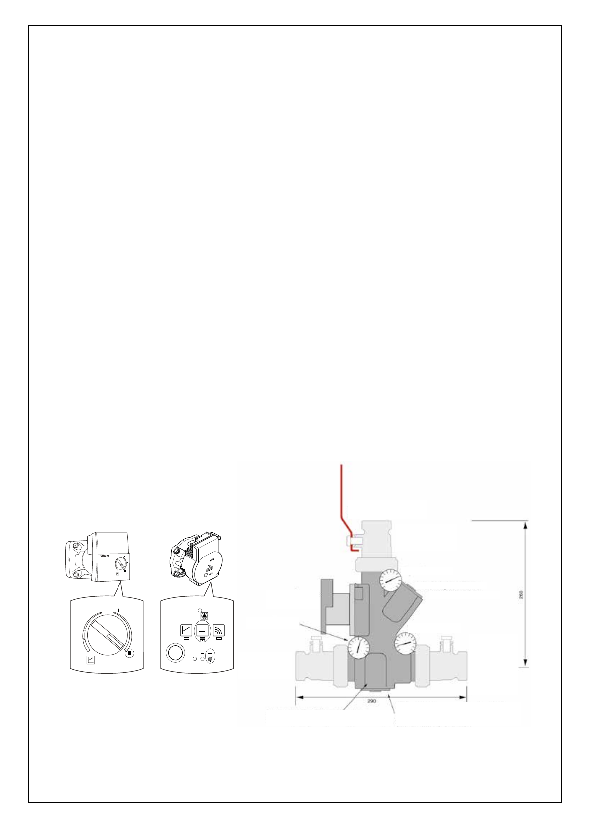
The Laddomat 22 is factory-fitted with a
thermostat No. 1456 which opens at 78 °C.
The thermostat No. 8719 opening at 72 °C is
included in the delivery (placed in the insulation of
the Laddomat 22).
For most installations, best the thermostat 78 °C is
proved. For boilers with a high output / low water
content as well as at systems with long pipe lines /
thin pipes, the thermostat opening at 72 °C may
be preferred. The thermostat cartridge with the
opening temperature of 72 °C should be used at
outputs above 35 kW.
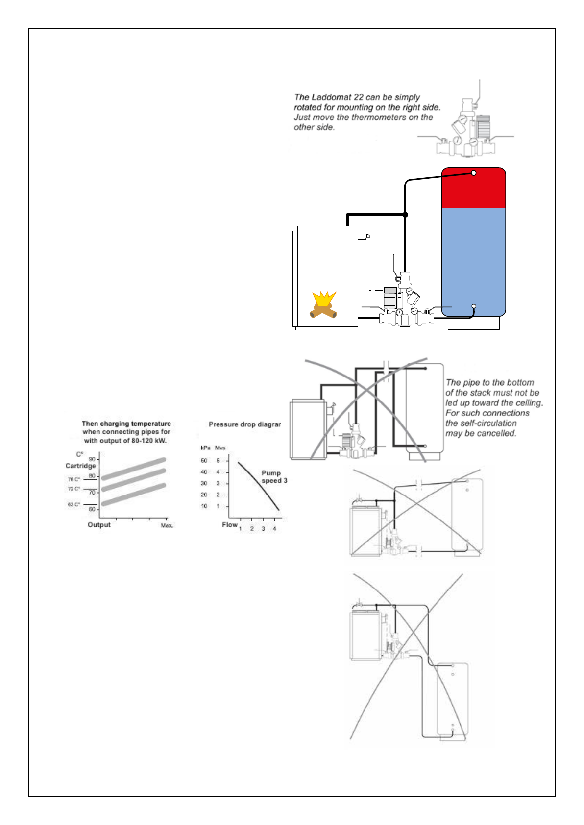
The higher charging temperature gives more
accumulated heat. In addition, the losses in the
boiler after the fuel burns out in the boiler with the
thermostat having the opening temperature of 78
°C will be smaller, because the connection
between boiler and storage tank will be interrupted
sooner than with the use of thermostat having the
opening temperature of 72 °C.
Different amounts of air bubbles in the fresh
water are present in all new systems.
This air releases inside the boiler walls after
heating the water. The more the boiler heats up,
the more air bubbles are released. We therefore
recommend heating the boiler to the highest
temperature when starting it for the first time.
When the air released in such a way accumulates
in the circulation pump, it can cause cessation of
the circulation. At low temperatures the air releases
more slowly and manages to be discharged
through the expansion or venting.
When a lot of air releases in the system, remove
the thermostat cartridge for a short time.
In extreme cases it is appropriate to make some
firings without use of the thermostat cartridge until
the water is free of air. Remove the spring, plunger
and thermostat cartridge and warm up the heating
system with the upper shut-off valve closed.
After the water is repeatedly heated to 85-95 °C
and free of air, remount the thermostat cartridge
into place.
If, despite these measures, there will be faults in
the system operation, check whether lint or other
debris are not in the pump preventing the
circulation. Also check that the system is installed
correctly according to the documentation.
Important at the first start up
Check that the circulation pump is switched off.
Close the three shut-off valves.
Unscrew the cover opposite the pump.
Remove the cover with spring, plunger and
thermostat cartridge from the Laddomat 22 (Fig. 1).
The thermostat cartridge is held in place on the
plunger by an O-ring.
The thermostat cartridge can be easily removed
from the plunger using a screwdriver (see Fig. 2).
Push a new thermostat cartridge into the plunger.
Reinstall all parts into place and tighten.
Open the shut-off valves.
Wait a few minutes before starting the pump to
allow any air to rise and escape from the system.
The device is now ready for operation.
Blocking the check valve
If you, for some reason, need to completely
disconnect the self-circulation, the check valve
must be blocked. The check valve is blocked using
the blocking clip, which is located at the bottom
of the EPP-insulation (Fig. 3), which is fastened
around the check valve axis according to Fig. 4.
To reach the axis, the spring needs to be removed.
Instructions for replacing the
thermostat in the Laddomat 22
Fig. 3
Fig. 1
Fig. 4
Zde je umístěna náhradní
termopatrona a zajišťovací spona
Zajišťovací spona
(zpětná klapka zablokována)
Changing regulation kit / Regelpaket wechseln
Thermostat not included / Thermoelement nicht enthalten
Old version / Alte Version, 212108:
New version / Neue Version, 212115:
22
Kryt - matice
Kryt - matice
Nová verze
Stará verze
Změna regulační sestavy
Neobsahuje termopatronu
Pružina
(prodloužená)
Pružina
Termopatrona
(termostat)
Termopatrona
(termostat)
O-kroužek
pístu
O-kroužek
pístu
Pružina škrtícího
ventilu
Škrtící ventil
Pouzdro ventilu
(plastová trojnožka)
O-kroužek
O-kroužek
Pouzdro
ventilu
Pouzdro
ventilu
Fig. 2
Lock
O-ring
Spring
Vlave
housing
Piston
O-ring
Thermostat
cartridge
Here there is a spare thermostat
cartridge and blocking clip
Blocking clip
(check valve blocked)

Connecting 2-3 tanks
When the pipe diameters are chosen properly and
the shortest length is respected, then everything
works OK, even at maximum heat consumption
of the heated object. Good functionality and self-
-circulation are also guaranteed even in case of a
power failure.
In this case, the recommended length of the pipe
between boiler and tank is 2 m. The total length is
then 2 + 2 m + 6 bends. The pressure loss of 1
bend corresponds to the pipe with a length of 1 m.
Boilers with a maximum output to:
80 kW min. Cu pipe 42x1.5 and/or R40
100 (120) kW, minimum Cu pipe or 54x2 or R50
Flow:
With the above mentioned dimensions, the Laddo-
mat 22 provides the flow of 3-4 m 3/h. See the flow
chart. For a longer piping the pipe diameter must
be increased.
Max. distance between the boiler and tank is 6 m,
it means that the total length is 6 + 6 m + 6 bends.
In case of special requirements for a self-circulati-
on the pipe diameter is proposed according to the-
se requirements.
Tanks are always placed as close as possible to
the boiler, next to each other. The piping distributi-
on from the bottom of the tank is always carried out
along the floor.
It is important that the flow into tanks during the
charging and discharging is distributed evenly.
When connected incorrectly, the charging will be
interrupted after charging one tank before all tanks
may be charged. The tanks are thus not fully ex-
ploited.
The same length of pipes
To achieve the same resistance in the piping, the
same length of the pipe distribution should be
mantained for each tank as far as possible.
Connecting with one tank
53
Potrubí ke dnu
zásobníku nesmí
být vedeno do výšky
směrem ke stropu.
U takového připojení
by došlo ke zrušení
samovolné cirkulace.
POZOR. Je-li
radiátor zapojen
tímto způsobem,
vzniká velké riziko
přetopení vody v
kotli a/nebo snížení
tepla dodávaného do
radiátorového okruhu.
Připojení na zásobník
1. Vedení potrubí znázorněné na výkresu je optimali-
zováno tak, aby se minimalizovaly provozní poruchy
způsobené vzduchem.
2. Trubku na teplou vodu vedoucí k přepouštěcím ven-
tilu lze připojit dvěma způsoby.
A. Cca 30 cm od vrchního okraje zásobníku, je-li
prioritou teplá užitková voda.
B. K přípojce pro připojení nabíjecího vedení k
zásobníku, je-li prioritou teplo. Připojení směřuje
dolů, aby vzduch nemohl stoupat do radiátorů.
Připojení 2 zásobníků
Zásobníky se umístí co nejblíže ke kotli, vedle sebe.
Vedení potrubí ze spodní cásti zásobníku se vede vždy
podél podlahy.
Je důležité, aby při nabíjení a vybíjení byl přítok do
zásobníků, resp. výtok z nich stejnoměrný. Při chybném
zapojení dojde k přerušení nabíjení zásobníku č.1 s te-
plou vodou a tato se vrátí ke kotli, než stihnout být zcela
nabity i ostatní zásobníky. Zásobník č. 2 tím zůstane
víceméně nevyužitý.
Po ukončení hoření se při chybném zapojení teplá voda
a teplo spotřebuje dříve, než by se dalo předpokládat,
protože zásobník č.1 vychladne rychleji než ostatní.
Nelze-li tyto zásady splnit, existují další možnosti
zapojení.
Stejná délka trubek
Pro dosažení stejného odporu je nutno zajistit, aby bylo
vedení potrubí k zásobníkům pokud možno přibližně
stejné. Toho lze dosáhnout následovně:
1. diagonálním zapojením nabíjecího okruhu A–A.
2. diagonálním zapojením radiátorového okruhu B–B.
Kromě toho by měly být rozměry trubek, které spojují
zásobníky, dostatečně velké, aby se ulehčila samotížná
cirkulace mezi zásobníky. Spojíme-li zásobníky
uprostřed, je to výhodné z toho důvodu, že dochází k
dalšímu rozdělení tepla.
Připojení přepouštěcího ventilu
Vstup teplé vody může být zapojen v bodě B, pokud
se upřednostňuje dodávka teplé vody, nebo v bodě B1,
pokud se upřednostňuje dodávka tepla.
Provoz elektrické topné patrony
Užívá-li se pouze topná patrona, je výhodnější ohřívat
jen první zásobník, aby se zabránilo tepelným ztrátám.
Uzavřete druhý zásobník pomocí ventilu umístěného na
dně zásobníku.
Laddomat 22 lze jednoduše
otočit pro montáž na pravou
stranu.
Stačí pouze přesunout
teploměry na druhou stranu.
Laddomat 22
> 6 m
> 6 m
Connection without self-circulation

1. Specified connection of the boiler with the Laddomat 22
2. Specified boiler connection with the thermostatic valve
ATTENTION- when the cooling loop to prevent overheating is connected, the check valve on the bypass of pump and thermal
valve may be omitted. In the case of placing the check valve on entry of water into the cooling loop to avoid a possible reverse
flow of water due to a pressure drop in the water distribution system, the cooling loop must be fitted with a safety valve 6 to 10
bar or closed expansion vessel with a min. volume of 4 l.
3. Best specified boiler connection with the Laddomat 22 with storage tanks
Boilers can be connected with open or closed expansion vessel. For the reason that the self-circulation of water extending the
boiler start-up to the desired temperature between the boiler and the storage tanks works properly, connect the flue thermostat
built in the boiler instead of the thermostat cartridge to switch on the pump in the boiler circuit. Thereby it is achieved that the
boiler pump will switch on when the boiler starts up. This alternative is permissible only in the case of connecting the boiler with
the Laddomat 22 or thermal valve TV 60 °C (65 °C).
06/2022
Laddomat 22
filtr
filter
filtr
filter
termostat
thermostat
80°C
mísící ventil
mixing valve
čerpadlo
pump
obytné místnosti
habitable rooms
plovoucí zpětná klapka
floating non-return flap valve
bojler TUV
DHW boiler
tlakoměr, pojistný
ventil, odvzdušnovač
pressure gauge, safety
valve, deaerator
otevřená expansní nádoba
open expansion vessel
tlaková
expansní
nádoba
pressure
expansion
vessel
ventil
valve
ventil
valve
ventil
valve
ventil
valve
přívod
supply
2 - 6 bar
10 - 15°C
odpad
outlet
ventil / valve
TS131 – 3/4A
(WATTS STS20)
plovoucí zpětná klapka
non-return flap valve
termoregulační
ventil
thermoregulating
valve
termostaty
thermostats
75°C 80°C
přívod
supply
2 - 6 bar
10 - 15°C
ventil / valve
TS130 – 3/4A
(WATTS STS20)
filtr
filter
mísící ventil
mixing valve
čerpadlo / pump
obytné místnosti
habitable rooms
tlakoměr, přetlakový ventil,
odvzdušňovací ventil
pressure gauge, safety
valve, deaerator
otevřená expansní nádoba
open expansion vessel
odtok
outlet
ventil
valve
ventil
valve
ventil
valve
filter
filter
ventil
valve
plovoucí zpětná klapka
floating non-return flap valve
bojler TUV
DHW boiler
ventil
valve
filtrfi
lter
akumulační nádrž
accumulation tank
přívod
supply
2 - 6 bar
10 - 15°C
ventil / valve
TS130 - 3/4A
(WATTS STS20)
filtr
filter
mísící ventil
mixing valve
čerpadlo/pump
obytné místnosti
habitable rooms
tlakoměr, pojistný ventil,
odvzdušnovač pressure
gauge, safety valve,
deaerator
tlaková
expansní
nádoba
pressure
expansion
vessel
akumulační nádrž
accumulation tank
otevřená expansní nádoba
open expansion vessel
boJler TUV
DHW boiler
odpad
outlet
MAX
60 °C
ventil
valve
ventil
valve
ventil
valve
ventil
valve
ventil
valve
ventil
valve
ventil
valve
ventil
valve
termostat
thermostat
40 - 60 °C
ventil
valve
Laddomat 22
Table of contents
Popular Water Pump manuals by other brands

DAB
DAB E.SYBOX MINI Instruction for installation and maintenance

Lincoln
Lincoln FlowMaster C Series Installation and maintenance guide

Vulcan-Hart
Vulcan-Hart FT48 CI Operation and Maintenance Training

Marina-Speroni
Marina-Speroni CAM 40 operating instructions

Mallory
Mallory 5250 instruction manual

Time Electronics
Time Electronics 7095 user manual