Atohm RS 700 GT EDITION User manual

OWNER’S MANUAL
RS 700 « GT EDITION » V1.2
PLEASE READ BEFORE USE

Page | 2
PRECAUTIONS & WARNINGS
The lightning flash with arrowhead symbol, within the equilateral triangle, is
intended to alert the user to the presence of uninsulated dangerous voltage
within the product’s enclosure that may be of sufficient magnitude to
constitute a risk of electric shock to persons. The exclamation point within an equilateral triangle is intended to
alert the user to the presence of important operating and maintenance (servicing) instructions in the literature
accompanying the appliance.
Before installing your amplifier, this user manual must be read thoroughly. If you have any doubts about how to
connect the equipment, ask for advice from your dealer.
- Do not expose to moisture (dripping, splashing) and do not introduce any foreign bodies into the device.
- Do not use near an excessive heat source (heating radiator, etc.).
- The power cord provided with the device meets power requirements. It should never be replaced with a lower
capacity model.
- Only connect the device to the type of power supply indicated on the device labeling or specific label. Before
connecting to the power supply, make sure your electrical installation can support the consumption of this device
and has a ground line. If in doubt, consult your electrician or the seller of your device.
- If the power cord does not fit perfectly into your power outlet, consult an electrician and replace the outlet. The
power cord should not be stepped on, crushed or pinched. The wall outlet must remain accessible.
- Do not overload wall outlets, multiple outlets or electrical extensions, as this poses a risk of fire or electrical
shock.
- Never open the device when it is connected to the power supply (risk of electrocution). When making an internal
adjustment, always make sure to put the cover back on before connecting the device to the power supply.
- Turn the amplifier "off" when not in use. During a storm or during long absences, make sure to unplug the power
cord (3).
- Ventilation: Ensure that the fan outlets are never blocked and can evacuate heat into a sufficient large volume.
- Fuse: In case of complete shutdown, check the power fuse (after disconnecting the power cord). For any fuse
replacement, use only an identical model to the original. If the problem persists, contact your dealer.
- Never connect a power output terminal (rep 21) of the amplifier to ground/earth (device chassis).
- Never interchange the "+" and "-" of the power outputs (REF 21) between the right and left channels.
- Never connect 2 pairs of speakers to the amplifier.
- Be careful to avoid short circuits on the speaker cables and the relevant terminals.
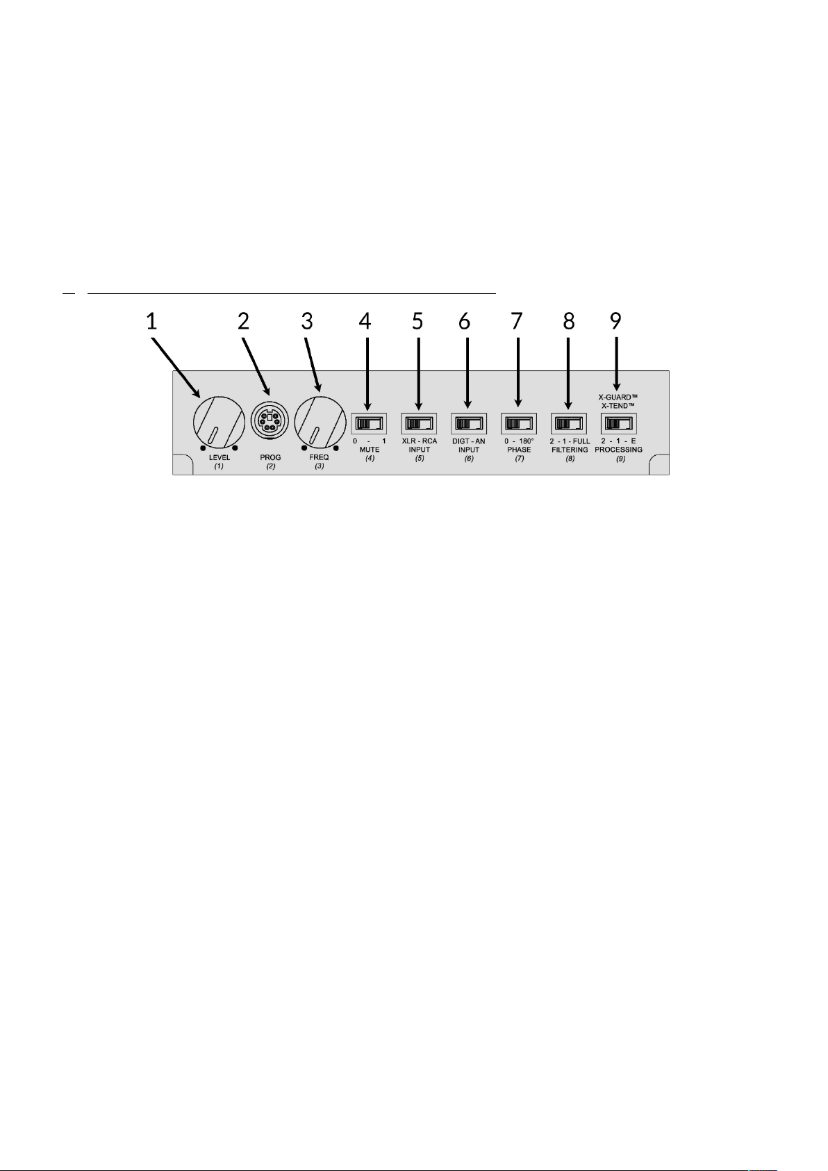
- Never manipulate switches 5,6,7,8,9 when the "Mute" switch (4) is on 1. Always do it when it is in position 0.
- For exterior cleaning of the device (not connected to the power supply), use only a soft, non-shedding, dry cloth
(we recommend using soft "microfiber" cloths). If the use of alcohol or soap-based products is possible, never use
products such as solvents or detergents.
-Once a year or according to their dirtiness, the ventilation grids (REF10) should be removed to be cleaned. This
cleaning is done outside with compressed air (preferably dehumidified and oil-free - prefer a spray can).
- Do not use any accessories other than those supplied with the device or explicitly recommended by the
manufacturer.
- Transportation: The device should always be transported in its original packaging. When using a cart, be careful
when moving the device to avoid injury from tipping over.
- Do not leave packaging bags within reach of children, as there is a risk of suffocation.
- In case of a technical problem, entrust this product to your dealer and/or an authorized service station.
Failure to follow these usage guidelines will result in the immediate voiding of the manufacturer's warranty.

Page | 3
PREAMBLE
Thank you for choosing our high performances ATOHM RS700 power amplifier "GT EDITION"
for your audio system.
With about 6000 hours of R&D, the RS700 power amplifier is highly innovative and resolutely
"hi-fi". It is based on a "double mono" structure driven by a high-performance analog/digital
board incorporating a DSP. Its signal processing capabilities are used to drive the power stages
(limiting, soft clipping, phase and amplitude correction, etc.) but also and especially to offer
advanced coupling of this amplifier with speakers through exclusive processing based, among
other things, on our knowledge of electroacoustics and, ultimately, on the exact specifications
of our driver units and coupled speakers.
The device's topology, the vast possibilities of programming and digital chaining make the
ATOHM RS700 base very versatile. Each unit is fully assembled, wired, controlled, and
programmed in our workshops. Depending on the applications, different versions are developed
and offered.
The ATOHM RS700 amplifier in this "GT EDITION" is a power unit operating in 4 modes. The
first mode (GENERAL mode) allows you to "drive" any type of speakers with power, dynamism,
finesse, and precision. The U-GUARD processing limits the power stages just before they
saturate and provides a soft clipping. Just like the other three modes, this first setup allows, if
needed, to (digitally) filter the speakers with a "high-pass" filter in order to truly relieve them in
the bass region and to associate, via the XLR outputs, one or two subwoofers to relieve them in
the lower frequency spectrum.
The other three modes (GT1-GT2 and GT3) are specific to each model of our GT SERIES
speakers. Amplification and speakers then work in symbiosis. The exclusive X-GUARD, T-
GUARD, U-GUARD, and X-TEND processing then come into action, allowing an increase in the
performance of our GT SERIES speakers in order to extract their ultimate essence.
Given the technologies and powers available, it is highly recommended to entrust the
commissioning to your dealer or a professional.
Before installation, the user should read this manual. He or she must also ensure the correct
internal configuration (choice of operating mode) of the device and that it corresponds well
with the connected audio devices (especially the speakers).
The three specific modes "GT1, GT2, and GT3" are very precisely calibrated for our ATOHM
GT1, GT2, and GT3 speakers. They should never be used with other speaker models.
During installation, all audio system components must be turned off.
We decline any warranty in case of error in configuration and/or improper setup
implementation.

Page | 4
NOTES REGARDING ATOHM'S EXCLUSIVE PROCESSING
• U-GUARD™ Processing (All Modes)
The U-GUARD™ processing aims to reduce the formation of square signals (clipping distortion) at the output of the
device and to avoid the saturation of the power stages at maximum power. The DSP constantly measures the
amplitude of audio signals. When it exceeds the set thresholds, the processing limits the amplitude of the signal
while maintaining its original form as best as possible. This process is calibrated so that the power stages are never
in saturation.
Typical analog circuits, often referred to as "soft clipping," provide a gentler clipping than a square signal. However,
they are often placed in a feedback loop and only react once the first rising front is established. U-GUARD™
processing goes further by acting from the first rising front and maintaining a signal shape that is closer to the
original and more pleasant to listen to. It also contributes to protecting the power stages and speakers in extreme
cases. This same processing is also applied to the low-level outputs to avoid any saturation on the XLR outputs.
In GT1 and GT2 modes, it is also U-GUARD™ that lowers the output power to make it compatible with these two
speaker models coupled with X-GUARD™ and X-TEND™ processing.
• T-GUARD™ Processing (General and GT1-GT2-GT3 Modes)
The power stages (class D) and their switch mode power supplies are designed to reproduce musical signals and
noise when considering a home theater use. Despite their excellent efficiency, from a thermal point of view, they
are not designed to deliver their full power for long periods on fixed signals. (which does not exist in an audio
signal)
In "general" mode, the T-GUARD™ processing manages the thermal parameters of the power stages in real-time. It
eliminates certain situations where the device is used inappropriately.
The DSP constantly analyzes and measures the audio signals transmitted to the power stages and calculates the
average power over a sliding period of 12 seconds. At the exceeding of the set thresholds, the algorithm triggers a
drop of -18 dB on all outputs of the device (power outputs and XLR outputs) to greatly reduce the power level for
a period of approximately 25 seconds.
In "GT1 GT2 and GT3" modes, the thermal limits are no longer those of the power stages but those of each
speaker model. In this context, the algorithm calculates an average over a sliding period of 6 seconds and compares
this average to the respective thresholds of each model. The high-frequency speakers have a lower permissible
power compared to the boomers. The protection therefore includes a weighting for high frequencies.
Note 1: This processing does not protect the system against installation, handling, and usage errors such as (but
not limited to) inappropriate connection, manipulation of cables (modulation, networks, etc.) with an under
powered device, full-level switch-flipping, feedback, inappropriate measurement signal, short-circuits, etc.
Note 2: Short-circuit protection is directly applied to the power stages. It intervenes in case of a short-circuit on
the connections, but also in some cases of damage to speakers & filters. It is generally indicated by micro-cuts
with a more or less significant degradation of the signal depending on the sound level. If this occurs, the amplifier
must be immediately turned off. The wiring & speakers must undergo a complete inspection before being put
back into operation. If in doubt, consult your dealer and/or an authorized service center.

Page | 5
• X-GUARD™ Processing ( GT1-GT2-GT3 modes only )
The X-GUARD™ processing ensures that the excursions of the bass speakers never exceed an absolute limit (too
high distortion and risk of breakage). This excursion control processing constantly analyzes the input signal and its
parameters (especially frequencies/amplitude) and compares them to a set of instructions. When the signal
becomes greater than the latter, it intervenes immediately to limit the amplitude of the signal without inducing
audible artifacts. X-GUARD™ preserves the integrity of the signal, its phase, and does not introduce group delay.
Its presence is completely undetectable to any measurement when it does not intervene on the signal. This
technology allows for the exploitation of all the available dynamics of the bass speakers without putting them in
danger. To some extent, the X-GUARD™ processing even allows for the reproduction of a musical range at slightly
higher sound levels.
IMPORTANT NOTE 1 (GT1, GT2 or GT3 mode): X-GUARD™ is very precisely calibrated for the bass-reflex loads
of the GT1-GT2 and GT3 speakers. It is therefore mandatory never to partially or totally obstruct the vents
(especially with the foam provided with the speakers). Given the available power, such action can lead to the
destruction of the bass speakers. We will decline any warranty claim in the case of destruction due to
implementation and setup error.
NOTE 2: FOR HOME THEATER USES (all modes): The various processes in use in the device induce a latency of
approximately 7.5ms. This value must be taken into account in the setting of your audio-video processor. It
should be noted that the subwoofer outputs (XLR) remain perfectly synchronized with the power outputs
regardless of the mode or setting used.
• X-TEND™ Processing ( GT1-GT2-GT3 modes only )
The X-TEND™ processing uses the precise knowledge of the bass-reflex speaker and its load, which has an
acoustic response equivalent to that of a high-pass filter. By conditioning the electrical signal relative to this model,
the X-TEND™ processing allows for the "reconstruction" of the speaker's response in the low frequencies. Unlike a
simple "boost" (EQ), its action aims to improve the group delay (especially deviations due to vents and speaker
alignment). Adjustable, it also allows you to choose the extension in the low frequency spectrum and, depending
on the setting, obtain a notably extended response compared to a conventional amplifier. This adjustable response
also allows, to some extent, to more or less "dose" the extreme bass depending on the room acoustics and speaker
placement. The extension of the response in the extreme bass causes larger excursions on the speakers. The X-
TEND™ processing works in conjunction with X-GUARD™ to maximize the speakers without ever exceeding their
limits.
NOTE 1: FOR HOME CINEMA USES (GT1-GT2 and GT3 modes): The X-TEND processing is not compatible with
home cinema use where the bass is managed/filtered by the audio-video processor's bass management.

Page | 6
LANDMARKS AND GETTING STARTED

Page | 7
1- Input level potentiometer
2- Programmation connector (for factory using only)
3- Multifunction digital potentiometer (can respond differently based on certain settings )
4- Mute ( position 0 = no output )
5- Analog input selector ( RCA or XLR)
6- Digital input selector ( not used in this amplifier version)
7- Phase selector for XLR output (subwoofers)
8- Filtering selector
9- Processing selector (can respond differently based on certain settings )
10- Venting grids
11- Main power switch
12- Aluminum control panel (setting protection)
13- Red LEDs – indicator for U-GUARD™ and T-GUARD™ thermal protection
14- Blue LEDs - Power-on indicator
15- Green LEDs –X-GUARD™ processing indicator
16- Low level asymmetrical RCA input
17- Low level asymmetrical XLR input
18- Low level asymmetrical XLR ouputs (for subwoofers)
19- S/PDIF digital input RCA 75ohms (not used in this amplifier version )
20- S/PDIF digital output RCA 75ohms (not used in this amplifier version )
21- Speakers power output (left and right )
22- 12V dc Trigger input output ( 3.5mm jack)
23- Trigger selector
24- Power inlet with fuse holder
Included accessories: 1 power cord - 1 BTR key for the aluminum panel
Please note that the digital inputs and outputs are exclusively intended for daisy chaining our devices. In
the context of this "GT EDITION" version, these inputs and outputs are not usable.
Although it is not its primary purpose, it is possible to connect the XLR and RCA inputs with 2 different
sources and use the switch (REF 5) to choose the input source. However, you must make sure to lower the
level of the source or input level to a minimum (REF 1) during such an operation.

Page | 8
1) CHOICE OF OPERATING MODE AND MAIN GAIN
Before starting, verify that the selected mode corresponds to the speaker model.
The choice of operating mode involves removing the device cover. The device must therefore be turned off with
the power cord definitely disconnected.
With a crosshead screwdriver (Type pozidrive 1), unscrew the 10 cover fixing screws. Then slide the cover to
access the DSP card settings on the front of the device.
"GENERAL" mode: usable with any type of speaker (minimum 3 ohms). Power output: 2*700W RMS / 4ohms.
"GT1" mode: to be used exclusively with ATOHM GT1 speakers. Power output: 2*220W RMS / 4ohms.
"GT2" mode: to be used exclusively with ATOHM GT2 speakers. Power output: 2*280W RMS / 4ohms.
"GT3" mode: to be used exclusively with ATOHM GT3 speakers. Power output: 2*700W RMS / 4 ohms.

Page | 9
Depending on the output level of your AV processor or preamplifier, you can choose the input sensitivity level via
a switch located on the same board. The "0dB" position provides a total gain of 29.8 dB. This setting is suitable for
the vast majority of system configurations. The "+15 dB" position provides a total gain of 44.8 dB. It is intended for
low-level preamplifiers/sources only.
Regardless of the chosen setting and the position of the potentiometer (Reference 1), the maximum input level
(XLR and RCA) should not exceed 22 dBu (9.75 Vrms).
NOTE ON DIGITAL SATURATION: When the red LEDs (REF 13) blink, there is a dynamic margin of about 10 dB before
saturation of the AD input converter (0dB Fs). When it is reached (inadequate level and dynamic), this saturation results
in a significant increase in distortion (digital saturation)
2) FONCTIONNALITY OF THE FRONT PANEL CONTROL
Regardless of the used mode(GENERAL or GT-1/GT2/GT3), except for control 9, the controls are common to all 4
modes.
REF 1: Input level adjustment potentiometer
REF 2: Programming socket (reserved for the factory)
REF 3: Multifunction digital potentiometer
REF 4: Mute (Position "0" silences the power stages)
REF 5: Source selector: balanced inputs (XLR) or unbalanced inputs (RCA)
REF 6: Digital input selector. Leave in "AN" position (analog)
REF 7: Phase adjustment for XLR subwoofer outputs
REF 8: High-pass filtering switch for speaker outputs
Position “2”: 24dB/octave slope (Linkwitz Rilley filter type)
Position “1”: 12dB/octave slope (Butterworth filter type)
Position “FULL”: No filtering (Response from 2Hz to 45kHz)
When in positions “1” or “2”, the digital potentiometer REF3 adjusts the level of the XLR subwoofer outputs.
REF 9: X-TEND™ processing switch (When REF 8 is in “FULL” position and only in GT1/GT2/GT3 modes)
Position “2”: Without X-TEND™ processing (normal response)
Positions “1” and E: X-TEND™ processing activated
The digital potentiometer REF 3 then adjusts the X-TEND™ processing.
REF 9: Cut-off frequency switch (when filtering switch REF 8 is in position “1” or “2”) (for all modes)
Position « 2 »: 60 Hz
Position « 1 »: 80 Hz
Position « E »: 100 Hz

Page | 10
3) TRIGGER CONTROL (12v)
The device's standby and power-on modes can be remotely controlled through the trigger input. To perform the
control, follow these steps:
- Connect one of the 12Vdc trigger jack inputs (3.5mm jack, REF 22) to the control system (preamplifier, processor,
or home automation) via a cable that is exclusively intended for this purpose (consult your dealer). The other jack
can then be used to transmit the control signal to another device.
- Set the rear TRIGGER switch (REF 23) to the "ON" position.
- Set the main power switch (REF 11) to the "ON" position.
- Set the "MUTE" switch (REF 4) to position "1".
NOTE: When this trigger control is configured, it is no longer possible to turn on the device in a conventional
manner.
4) MAINS CABLE AND CONNECTION
Designed with a "double isolation" architecture, the RS700 amplifier is nevertheless equipped with class 1
protection. This means it must be grounded. Amplifier is designed to operate with a mains voltage between 100
and 240 V (50 Hz - 60 Hz). It automatically detects this voltage and adjusts accordingly.
The mains cable supplied with the device has a large section (type H05VV-F
1.5MM2 -3G section 3 * 1.5²) with a ground connection. It must not be replaced
by a cable with a smaller section (including export version) or by a model without a
ground connection.
5) SPEAKER & MODULATION CABLES
The speaker output terminals (REF21) can accept high-section speaker cables. Depending on the speakers model
and distance the minimum section should be between 2.5² and 5².
Make sure to properly strip the cables (17mm) and that no strand of cable causes a short circuit between the (+)
and (-) terminals or with the device's chassis. In the case of using forks (spades), make sure the ends of the forks do
not touch and cause a short circuit.
Asymmetrical RCA modulation cable connections never exceed a few meters. Longer connections require the use
of symmetrical modulation cable via the XLR inputs (REF 17) of the device.
Our "ZEF SERIES" cables range meets all needs for connecting this device. We invite you to consult your dealer.
NOTE: The circuit protection located on the power stages only protects the device from short circuits
between the (+) and (-) respective terminals.

Page | 11
6) LED INDICATORS
Blue LEDs (REF 14): device is powered on / main switch is on
Red LEDs (REF 13): U-GUARD™ Processing (operates in all modes)
T-GUARD™ Processing (operates in all modes)
The U-GUARD™ processing intervenes on the signal to limit power and prevent clipping/saturation of power
stages. A brief or rhythmic flashing of the LEDs indicating activation of the processing is normal and poses no
problem even at high levels. Sustained flashing of the LEDs indicates that the average power delivered is very high
and should prompt the user to lower the sound level (audio signal degradation, speaker thermal compression).
The T-GUARD™ processing provides thermal protection for the amplifier (GENERAL mode) and the associated
speakers (GT1-GT2 or GT3 mode only). When the system is subjected to extreme stress, the processing triggers
protection by lowering the level by 18dB and lighting the red LEDs permanently. This level drop is also propagated
to the subwoofer outputs.
In "GENERAL" mode, the processing is set to protect the amplifier power output stages. In "GT1-GT2 or GT3"
mode, the processing is set to protect the speakers (and therefore the amplifier power output stages).
The sudden and general drop in sound level combined with the permanent lighting of the red LEDs requires
lowering the volume. After a delay of approximately 25 seconds, the red diodes will turn off and listening can
resume normally.
Green LEDs (REF 15): X-GUARD processing
These LEDs flash when the X-GUARD™ (speaker excursion control) processing intervenes on the signal to prevent
excessive excursions on woofer(s) units. If this is only briefly or slightly in rhythm with the audio signal, this is not a
problem in itself. However, sustained flashing of these green LEDs indicates inappropriate use and should prompt
the user to lower the sound level and/or reduce the correction amplitude of the X-TEND™ processing when it is
used.
Note: when power is on and depending on the setting, the red and green LEDs may flash briefly. This is a normal process.
A delay of approximately 5 seconds then occurs to allow the circuits to stabilize.
7) INPUT LEVEL ADJUSTMENT
To obtain the best signal-to-noise ratio on your audio system, it is advisable to maximize the level of the source
(adjustable level preamp / DAC-streamer / audio-video processor) and reduce the level of the input potentiometer
(REF 1) of the amplifier.
As a first approach, you can position the input potentiometer (REF 1) between 12 o'clock and 1 o'clock. You can
then adjust if necessary.
8) NORMAL USAGE WITHOUT X-TEND PROCESSING (all modes)
REF 8: Filtering selector in "FULL" position
REF 9: Processing selector in "2" position

Page | 12
9) USAGE WITH X-TEND PROCESSING ( GT1 -GT2 et GT3 mode only )
-REF 8 : filtering selector in position « FULL »
-REF 9 : processing selector in position « 2 » (or 1)
-REF 3 : adjustment « FREQ » potentiometer ( 11 steps)
10) STEREO SETUP (all mode)
In GENERAL mode: compatible with speakers of all types (impedance of at least 3.3 ohms).
In GT1-GT2 and GT3 mode: compatible with ATOHM GT1-GT2 or GT3 speakers only. The X-GUARD and X-
TEND processing specific to each model is then activated.
Depending on the preamp capabilities, you can use XLR inputs (REF 17) or RCA inputs (REF17). You can also use a
variable level source (DAC/STREAMER) by making sure the "variable level" option has been activated in the device.
Generally, it is strongly advised to turn on the source and check the output level setting before turning on the
amplifier.
Make sure to never interchange the (+) or (-) polarity of the right channel with the (+) or (-) polarity of the left
channel. Make sure to respect the positive and negative polarities of each output channel and the input terminal
polarities of the speakers.

Page | 13
11) STEREO WITH SUBWOOFER(S) SETUP (all mode)
TYPE 2.1
TYPE 2.2
Depending on the preamp capabilities, you can use XLR inputs (REF 17) or RCA inputs (REF17). You can also use a
variable level source (DAC/STREAMER) by making sure the "variable level" option has been activated in the device.
Generally, it is strongly advised to turn on the source and check the output level setting before turning on the
amplifier.

Page | 14
For the speakers :
In GENERAL mode: compatible with speakers of all types (impedance of at least 3.3 ohms).
In GT1-GT2 and GT3 mode: compatible with ATOHM GT1-GT2 or GT3 speakers only. The X-GUARD and X-
TEND processing specific to each model is then activated.
Make sure to never interchange the (+) or (-) polarity of the right channel with the (+) or (-) polarity of the left
channel. Make sure to respect the positive and negative polarities of each output channel and the input terminal
polarities of the speakers.
For subwoofer(s)
2.1 SETUP
Connect the XLR subwoofer outputs (REF18) to the RCA type low-level inputs of the active subwoofer (This
requires a specific XLR to RCA cable/consult your dealer).
2.2 SETUP
Connect the XLR subwoofer outputs (REF) to the XLR type low-level inputs of the active subwoofers (conventional
XLR cables). If your subwoofers do not have XLR inputs, you can use specific XLR to RCA cables (Consult your
dealer).
SETUP FOR STEREO CONFIGURATION WITH SUBWOOFER(S)
Regardless of the selected mode, the filtering switch (REF 8) should be set to position “2” (24dB/oct slope) or
position “1” (12dB/oct slope) based on the chosen filtering type. Once this switch is engaged in position “1” or “2”,
the processing switch (REF 9) allows you to choose the cutoff frequency of the high-pass filters applied to the
power/speaker outputs (REF 21).
REF (9) processing selector : Position “2” : 60 Hz Position “1” :80 Hz Position” E” : 100 Hz
In this configuration, the potentiometer (REF 3) allows you to adjust the level of the subwoofer outputs (XLR),
while the selector (REF 7) allows you to set the phase (0 or 180°).

Page | 15
Note 1: The subwoofer outputs (XLR) include a Bessel-type low-pass filter (12dB/oct - 400Hz). It is only there to
make the work of the limiters on some subwoofers easier. It does not affect the frequency response in their
usable band.
Note 2: The cutoff frequency (low-pass filter) of the subwoofers must be adjusted on the subwoofer(s) .
Note 3: The subwoofer outputs are only active when the REF8 filtering switch is in position “2 or 1”.
Note 4: The potentiometer (REF3) allows you to adjust the output volume of the XLR outputs (REF 18) for the
subwoofers. When it is in the maximum position, the relative level is +8dB relative to the speaker level. Adjust the
volume on the subwoofer(s) so that it is approximately +8 to +10 dB higher than that of the speakers. The
potentiometer (REF) will then allow you to adjust the subwoofer level downwards.
Note 5: In configuration 2.2, be sure to set both subwoofers exactly the same in all aspects (cutoff frequency,
volume, filtering slope, phase at 0°).
Note 6: Filtering slope and theoretical principles choice
The following notes and graphs are theoretical and deliberately simplified. They do not take into account the
actual acoustic responses of the speakers and subwoofers and their placement in a listening room with all its
imperfections. Nevertheless, they allow you to understand some basic principles to adjust your system to the
best.
The cutoff frequency of the speaker output high-pass filters can be chosen between 12dB/oct and 24 dB/oct. As
for the subwoofers, the filtering slope is generally 12 or 24dB/oct depending on the model.
In position "1", the three 12 dB/oct high-pass filters of the amplifier are of the Butterworth type. Ideally, the low-
pass filter of the subwoofer(s) should also be of the Butterworth type 12dB/oct. With this type of filter, the
connection point is made at -3dB with phase inversion (REF7 at 180°) on the subwoofer outputs. This kind of
filtering clearly favors energy and dynamics. The amplitude of the sum in the overlap band peaks at +3dB at the
connection point (-3dB). Choosing slopes of 12dB/oct generally provides a low group delay.

Page | 16
From the previous example, it's possible to make a compromise to obtain a more linear overall response. By
shifting the cut-off frequency to 60Hz on the subwoofers, the maximum amplitude of summation in the overlap
band decreases from +3dB to only 1.4dB.
By following the same principle, it's possible to obtain a nearly linear overall response. By shifting the cut-off
frequency to 60Hz on the subwoofers and shifting that of the speakers to 100Hz, the maximum amplitude of
summation in the overlap band decreases from +3dB to only +/- 0.5dB.
In position "2", the three 24dB/oct high-pass filters of the amplifier are of the Linkwitz Rilley (LR) type. Ideally,
the low-pass filter of the subwoofers should also be LR 24dB. With this type of filters, the crossover point is made
at -6dB without phase inversion on the subwoofer outputs (Phase selector REF 7 on 0°). This filtering clearly
favors the linearity of the system response. The amplitude of the summation in the overlap band remains linear.
Choosing slopes of 24dB/oct reduces reduce some distortions in the rejection bands. However, it induces a larger
group delay than with slopes of 12dB/oct.

Page | 17
In GT1, GT2 or GT3 mode: we suggest the following cutoff frequencies:
GT1: 80 Hz or 100 Hz (60Hz is possible with slope of 24dB/oct)
GT2: 60Hz or 80Hz
GT3: 60Hz or 80Hz
Note 7: Regardless of the filtering selected, an incorrect adjustment of the phase selector (REF7) of the
subwoofer outputs (XLR) leads to a strongly degraded response with level cancellation in the overlap band. This
results in listening by a significant lack of "dynamic" in the bass accompanied by an obvious lack of homogeneity.
(The feeling that speakers and subwoofer(s) play on their own).
Never attempt to correct this type of response with a room correction/equalization device.
Note 8: Some subwoofers use internal digital processing to perform low pass filtering and other functions. This
digital processing involves a latency often equal to 1 to 2 ms. Unless the loudspeakers are delayed by an identical
amount, this pure delay systematically leads to a degradation of the response in the overlap band .

Page | 18
12) BASIC HOME THEATER CONFIGURATION (All mode)
Depending on the preamp/processor capabilities, you can use XLR inputs (REF 17) or RCA inputs (REF17). You can
also use a variable level source (DAC/STREAMER) by making sure the "variable level" option has been activated in
the device. Generally, it is strongly advised to turn on the source and check the output level setting before turning
on the amplifier.
Make sure to never interchange the (+) or (-) polarity of the right channel with the (+) or (-) polarity of the left
channel. Make sure to respect the positive and negative polarities of each output channel and the input terminal
polarities of the speakers.
SETTINGS FOR BASIC HOME-THEATER CONFIGURATION ( All mode)
-REF 8 : Filtering selector in position «
FULL »
-REF 9 : Processing selector in position «
2 »
Whatever the mode used, the filtering being carried out by the audio-video processor, the filtering switch (REF8)
must remain in the "FULL" position.

Page | 19
In GT1-GT2 and GT3 mode: with ATOHM GT1-GT2 or GT3 loudspeakers only. The X-GUARD and X-TEND
processing specific to each model is then activated.
For a home-theater configuration, it is mandatory deactivate X-TEND processing by setting the processing selector
(REF9) to position “2” . (This processing is not compatible with the bass management of audio video processors).
Note 1: Digital signal processing and various applied processing induce a latency of 7.5ms. Please take this value
into account for correct home theater processor setting. (For reference, for sound, this corresponds to a traveled
distance of 2.57m)
Note 2 (GENERAL mode): The signals sent by the audio-video processor can either be filtered (small mode) or full-
band (large mode). High-pass filtering in small mode reduces speaker excursions at low frequencies but does not
provide absolute protection. Given the available power, we advise caution regarding the sound levels reproduced
on the speakers and ensuring they remain compatible with the speakers. (Including during room
calibration/equalization procedures).
13) MIXED STEREO / HOME THEATER CONFIGURATION (All mode)
This configuration corresponds to that described in Chapter 11 (STEREO CONFIGURATION WITH SUBWOOFER)
with the addition of an audio-video processor. The RCA inputs and XLR inputs are used to connect the two input
sources (a stereo preamplifier or a variable level source and an audio-video processor) to the device.
Make sure to never interchange the (+) or (-) polarity of the right channel with the (+) or (-) polarity of the left
channel. Make sure to respect the positive and negative polarities of each output channel and the input terminal
polarities of the speakers.

Page | 20
The input selection is done through the
REF5 analog source selector.
In order to obtain the best Hi-Fi and HOME-CINEMA audio performance, the subwoofer(s) must be connected to
the XLR subwoofer outputs (Ref 18) as indicated in Chapter 11.
The audio-video processor should be set by indicating the absence of a subwoofer connected to it. It should also
be configured with the front two speaker channels (L and R) in "large" mode and the other channels in "small"
mode. In this way, the LFE channel will be redirected to the 2 main output channels (front L and R) of the audio-
video processor.
The L and R signals from the processor are enhanced with the LFE channel. They therefore contain a greater
amount of bass and sub-bass. It is therefore imperative to filter the speaker outputs and direct this range to the
subwoofer(s). For this purpose, the filtering selector (REF 8) must be placed in position “2” (24dB/oct filter) or “1”
(12dB/oct filter). Once this switch is engaged in position 1 or 2, the processing selector (Ref 9) allows you to
choose the cutoff frequency of the high-pass filters applied to the speakers power output (Ref 21). In this
configuration, the potentiometer REF 3 allows you to adjust the level of the subwoofer outputs (XLR) while the
switch (REF 7) allows you to adjust the phase (0 or 180°).
For filter adjustment, please refer to notes 1-2-3-4 and 5 in Chapter 11.
Note 1: The digital signal processing and various processing applied in the device result in a latency of 7.5ms.
Please take this value into account for correct processor configuration. (As a reference, for sound, this
corresponds to a distance traveled of 2.57m).
Note 2: The subwoofer outputs are only active when the REF8 filtering switch is in position “2” or “1”.
Note 3: The cutoff frequency (low-pass filter) of the subwoofers must be adjusted on the subwoofer(s). There is
no need to change this setting when switching from one source to another.
Note 4 (“GENERAL” mode): The signals sent by the audio-video processor are increased by the LFE channel. Also,
the filtering switch (REF8) must be placed in position “2” (24dB/oct filter) or on “1” (12dB/oct filter). The high-
pass filtering reduces speaker excursions at low frequencies but does not provide absolute protection. Given the
available power, we advise you to be cautious about the sound levels reproduced on the speakers and to ensure
that they are compatible with the speakers in case of calibration (room equalization).
For small or medium-sized speakers, we recommend setting their cutoff frequency to 80 or 100 Hz (REF9
selector in position “1” or “E”) with a 24dB/oct slope (REF8 selector in position “2”).
Note 5: Some audio-video processors offer a "double bass" setting. This option should not be activated.
Note 6: Automatic room equalization devices may have erratic behaviors and may change the parameters of
speaker output management and the LFE channel. It is therefore imperative to check that the two speaker
output channels remain in "wide" mode after calibration and the coherence of the proposed calibration.
Note 7: Before proceeding with a calibration, listen to your system and make sure the filtering is properly
performed without phase adjustment error (REF 7).
Note 8: Be sure to strongly reduce the level of the sources when you want to switch from one to another via the
source selector REF5.
This manual suits for next models
3
Table of contents
Other Atohm Amplifier manuals