6 ©2007 • All rights reserved.
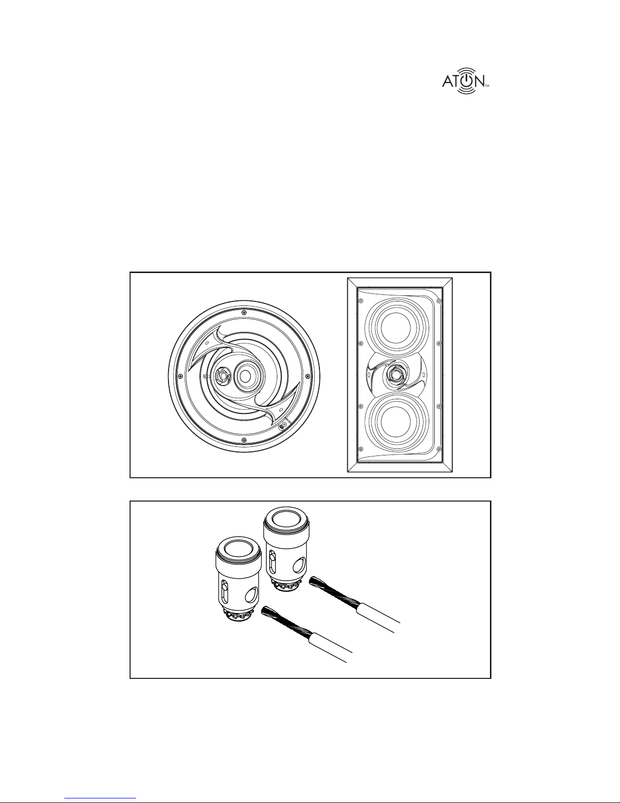
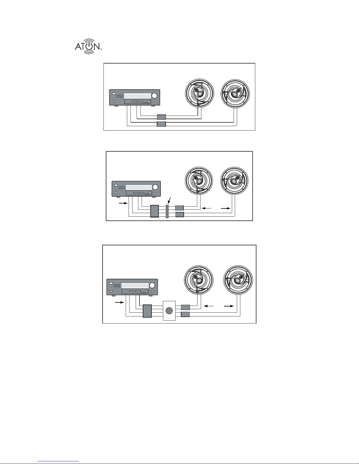
Storm Series LCR Theater Speakers
A/V Receiver/Amplifier
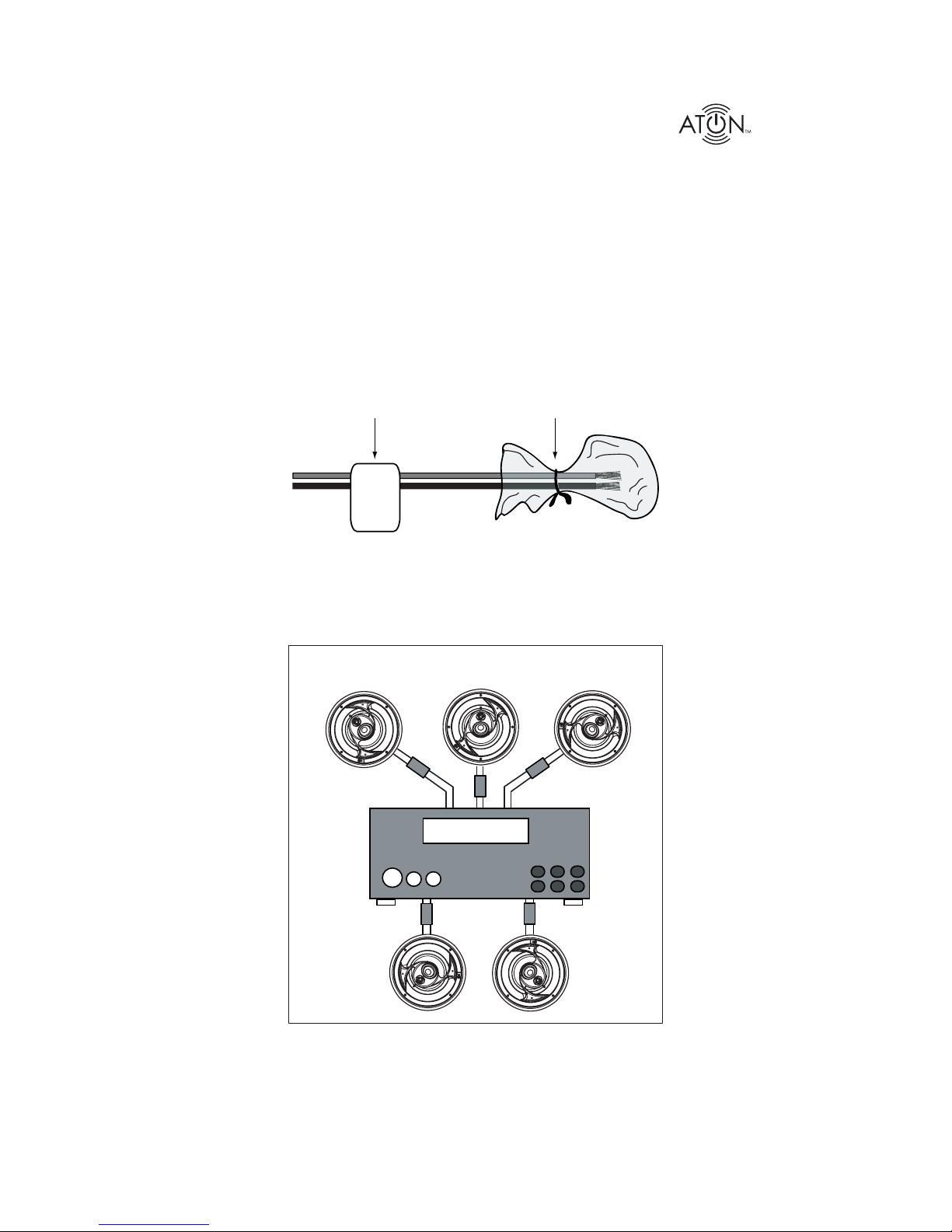
• Two separate 2 conductor speaker wires run from the A/V Receiver
or amplifier to each stereo speaker.
+
-
+
-
+
-
+
-
Figure 3.3: Wiring: Amplifier to Speakers - 2 Conductor Direct
• One 4-conductor speaker wire runs from the amplifier to a splice near
one speaker. A 2-conductor wire runs from the splice to each speaker.
A/V Receiver/Amplifier
+
-
+
-
+
-
+
-
Splice
4
Conductor
Wire
2
Conductor
Wire
Figure 3.4: Wiring: Amplifier to Speakers - 4 Conductor to 2 Conductor
Volume
Control
• One 4 conductor speaker wire runs from the amplifier to a stereo
volume control, then one 2 conductor speaker wire runs to each
stereo speaker.
+
-
+
-
+
-
+
-
A/V Receiver/Amplifier
4
Conductor
Wire
2
Conductor
Wire
Figure 3.5: Wiring: Amplifier to Speakers w/ Volume Control
Note 1: Low voltage wiring must be run in accordance with the National Electrical Code as well as any other applicable provi-
sions of the local building codes in your area. In some cases (such as commercial installations), running the wire in conduit
may be required. If you have any questions concerning the wiring of speakers in your home, contact your local building and
inspection department.
Note 2: It is recommended that you use quality CL-2 or CL-3 rated stranded speaker wire when installing ATON speakers.
Solid-core “Romex” type wire is not acceptable! Use at least 16AWG speaker wire for runs up to 100 feet, and at least 14 AWG
speaker wire for runs up to 200 feet. If you must cross high-voltage lines, always do so at a 90 degree angle to avoid audible
hum through the speakers!.
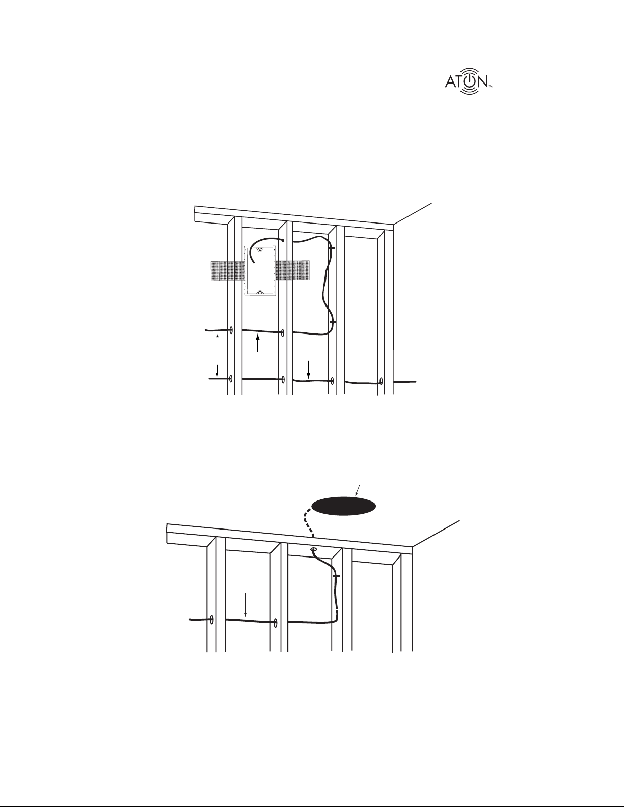
Note 3: When pre-wiring for ceiling speakers, it is essential to make direct wire runs from the head-end to each speaker. Do not
run speaker wires in series or parallel, and do not “daisy-chain” speakers to common wiring.