Atos DEP/T6 User manual

Version: 04.01 Classification: Public
Haachtsesteenweg 1442
1130 Brussels
Belgium
DEP/T6 Owner's Manual
DEP Documentation

ATOS Worldline - Technologies & Products Page: 2/55
DEP/T6 Owner's Manual (04.01)Classification: Public
CONFIDENTIALITY
The information in this document is confidential and shall not be disclosed to any
third party in whole or in part without the prior written consent of Atos Worldline
S.A./N.V.
COPYRIGHT
The information in this document is subject to change without notice and shall not
be construed as a commitment by Atos Worldline S.A./N.V.
The content of this document, including but not limited to trademarks, designs,
logos, text, images, is the property of Atos Worldline S.A/N.V. and is protected by
the Belgian Act of 30.06.1994 related to author’s right and by the other applicable
Acts.
The contents of this document must not be reproduced in any form whatsoever, by
or on behalf of third parties, without the prior written consent of Atos Worldline
S.A./N.V.
Except with respect to the limited license to download and print certain material
from this document for non-commercial and personal use only, nothing contained
in this document shall grant any license or right to use any of Atos Worldline
S.A./N.V.’s proprietary material.
LEGAL DISCLAIMER
While Atos Worldline S.A./N.V. has made every attempt to ensure that the
information contained in this document is correct, Atos Worldline S.A./N.V. does
not provide any legal or commercial warranty on the document that is described in
this specification. The technology is thus provided “as is” without warranties of
any kind, expressed or implied, included those of merchantability and fitness for a
particular purpose. Atos Worldline S.A./N.V. does not warrant or assume any legal
liability or responsibility for the accuracy, completeness, or usefulness of any
information, product or process disclosed.
To the fullest extent permitted under applicable law, neither Atos Worldline
S.A./N.V. nor its affiliates, directors, employees and agents shall be liable to any
party for any damages that might result from the use of the technology as described
in this document (including without limitation direct, indirect, incidental, special,
consequential and punitive damages, lost profits).
JURISDICTION AND APPLICABLE LAW
These terms shall be governed by and construed in accordance with the laws of
Belgium. You irrevocably consent to the jurisdiction of the courts located in
Brussels for any action arising from or related to the use of this document.
sa Atos Worldline nv – Chaussée de Haecht 1442 Haachtsesteenweg
B-1130 Bruxelles-Brussel - Belgium
RPM-RPR Bruxelles-Brussel -TVA-BTW BE 0418.547.872

ATOS Worldline - Technologies & Products Page: 3/55
DEP/T6 Owner's Manual (04.01)Classification: Public
Version Management Report
Version
Name(s)
Date
Comments
01.00
Luc Braems
12-Jun-2006
Initial version – Delivered-to-Deltate
01.01
Luc Braems
11-Jul-2006
Pictures added, various corrections and
improvements; review comments
04.00
Anna Papayan
04/03/2011
Change the template into Atos
Worldline, minor changes.
04.01
Anna Papayan
12/05/2011
Add the number of max host
connections, automatic failover from
Venus 4.2.7.

ATOS Worldline - Technologies & Products Page: 4/55
DEP/T6 Owner's Manual (04.01)Classification: Public
TABLE OF CONTENTS
TABLE OF CONTENTS ............................................................................................4
1. SCOPE OF THE DOCUMENT .........................................................................6
1.1. AUDIENCE.......................................................................................................6
1.2. DOCUMENT ORGANISATION ............................................................................6
1.3. REFERENCES ...................................................................................................7
1.4. TYPOGRAPHICAL CONVENTIONS .....................................................................7
1.5. ABBREVIATIONS AND ACRONYMS ...................................................................8
1.6. CONTACTING ATOS WORLDLINE...............................................................8
2. DEP/T6 OVERVIEW..........................................................................................9
2.1. DEP/T6 FEATURES..........................................................................................9
2.2. CHECKING THE SHIPMENT CONTAINER............................................................9
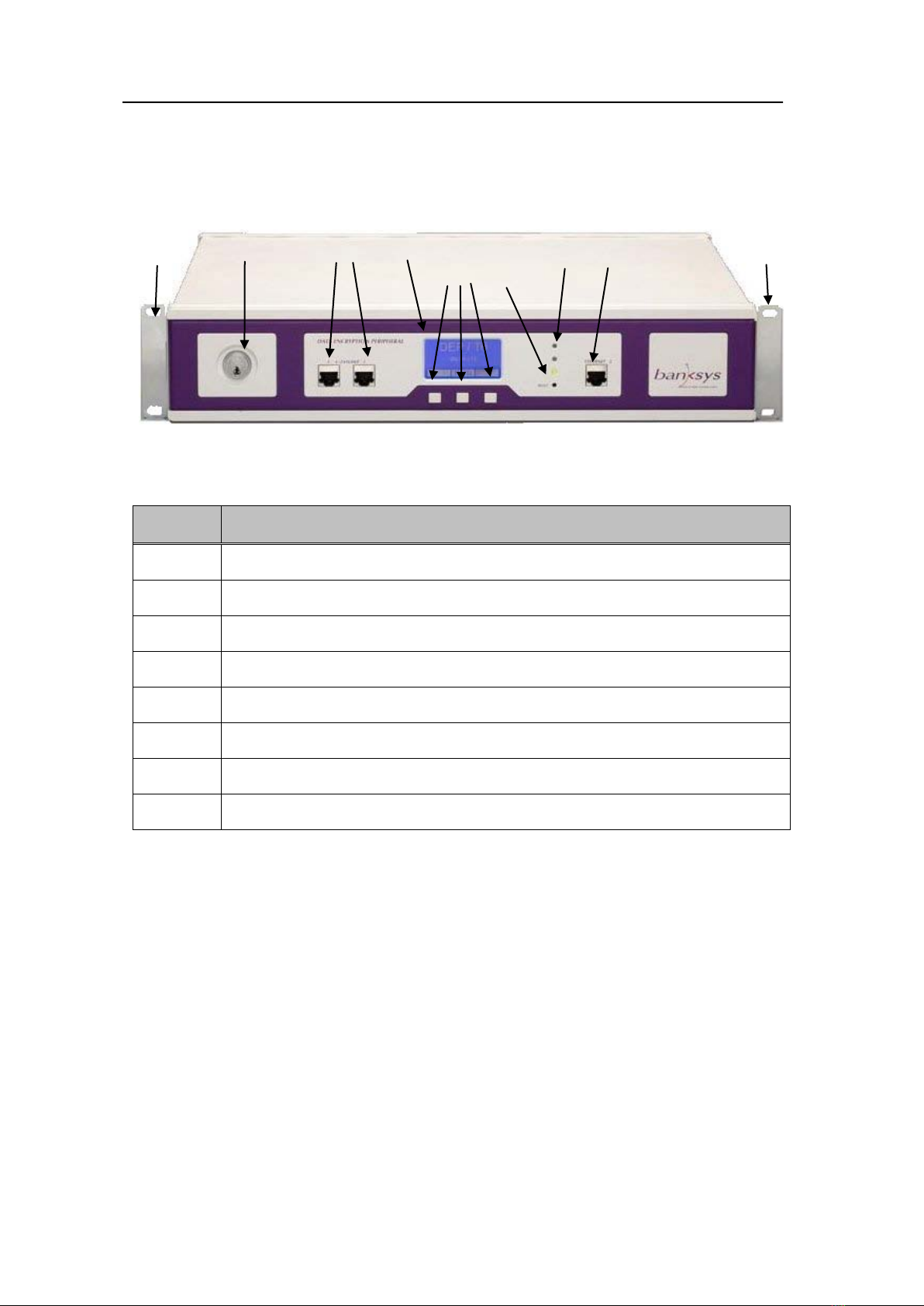
2.3. HARDWARE OVERVIEW.................................................................................10
2.3.1. Front view............................................................................................10
2.3.2. Rear view .............................................................................................11
2.4. UNDERSTANDING THE USER INTERFACE........................................................11
2.4.1. Basic controls.......................................................................................11
2.4.2. Status LEDs..........................................................................................12
2.4.3. Types of screens...................................................................................12
2.4.4. Navigating through the screens...........................................................15
2.4.5. Entering data .......................................................................................16
2.4.6. Identification........................................................................................17
2.4.7. Storing settings.....................................................................................19
2.4.8. Changing the LCD set-up ....................................................................19
3. INSTALLING THE DEP/T6............................................................................21
3.1. PREPARING THE INSTALLATION.....................................................................21
3.1.1. Dimensions...........................................................................................21
3.1.2. Required tools and parts......................................................................21
3.1.3. Preventing Electrostatic Discharge damage .......................................22
3.1.4. Site requirements .................................................................................22
3.2. INSTALLING THE DEVICE IN A RACK ..............................................................22
3.2.1. Attaching the chassis to the rack posts................................................22
3.2.2. Attaching the chassis ground connection ............................................23
3.3. CONNECTING I/O CABLES .............................................................................24
3.3.1. Choosing an Ethernet port...................................................................24
3.3.2. Making a serial connection..................................................................24
3.4. CONNECTING POWER.....................................................................................25
4. STARTING AND CONFIGURING.................................................................25
4.1. CHECKING STATUS........................................................................................25
4.1.1. Ethernet................................................................................................26
4.1.2. Board serial number............................................................................26
4.1.3. Software revisions................................................................................27
4.1.4. System status........................................................................................27
4.2. COMPLETING BASIC SYSTEM CONFIGURATION ..............................................28

ATOS Worldline - Technologies & Products Page: 5/55
DEP/T6 Owner's Manual (04.01)Classification: Public
4.2.1. Selecting an Ethernet jack ...................................................................28
4.2.2. Managing the watchdog.......................................................................28
4.2.3. Setting the Platform Name...................................................................29
4.2.4. Setting date and time............................................................................29
4.2.5. Setting the IP-addresses.......................................................................30
4.2.6. Managing event logging ......................................................................32
4.3. COMPLETING APPLICATION SETTINGS...........................................................33
4.3.1. Network Mgt Agent..............................................................................33
4.3.2. HOST port............................................................................................35
5. MANAGING USER ACCOUNTS ...................................................................35
5.1.1. Listing user accounts ...........................................................................35
5.1.2. Adding a user account .........................................................................36
5.1.3. Changing the PIN code........................................................................38
5.1.4. Removing a user account.....................................................................39
6. SHUTTING DOWN – RESETTING...............................................................41
6.1. SHUTTING DOWN...........................................................................................41
6.2. RESETTING....................................................................................................41
7. UPGRADING THE DEP/T6.............................................................................42
7.1. STARTING AN UPGRADE ................................................................................42
7.1.1. Types of upgrades................................................................................42
7.1.2. Starting.................................................................................................43
7.1.3. Aborting ...............................................................................................43
7.2. UPGRADING OS SOFTWARE...........................................................................44
7.3. UPGRADING THE PLATFORM SOFTWARE........................................................45
8. USING THE DEP/T6.........................................................................................47
9. READING THE LOGGING INFORMATION..............................................48
9.1. TYPES OF INFORMATION................................................................................48
9.1.1. System monitoring information............................................................48
9.1.2. System management information.........................................................48
9.2. LOGGING DATA FORMAT ...............................................................................49
10. TROUBLESHOOTING................................................................................50
11. SAFETY INFORMATION...........................................................................52
11.1. COMPLIANCE ................................................................................................52
11.1.1. Electrical codes....................................................................................52
11.1.2. CE certification....................................................................................52
11.2. SAFETY RECOMMENDATIONS........................................................................52
11.2.1. Operating the DEP/T6.........................................................................52
11.2.2. Servicing ..............................................................................................53
11.2.3. Disposal of the appliance.....................................................................53
12. TECHNICAL SPECIFICATIONS ..............................................................54
13. APPENDIX: USER INTERFACE STRUCTURE......................................55

ATOS Worldline - Technologies & Products Page: 6/55
DEP/T6 Owner's Manual (04.01)Classification: Public
1. SCOPE OF THE DOCUMENT
This document describes the installation and the configuration of the DEP/T6
cryptographic appliance, setting up of user accounts, upgrading of system and
platform software and first-line troubleshooting of the system.
Information about such topics as DEP module software, key management,
cryptographic applications are not within the scope of this document. Refer to the
References section on page 7 for details on the guides, command references and other
documents related to those topics.
1.1. AUDIENCE
This document is primarily designed for the person(s) responsible for installing,
maintaining, and troubleshooting the DEP/T6. The users of this manual should be
familiar with electronic circuitry and wiring practices and should also have experience
in installing networking equipment.
Certain procedures described in this manual require the presence of a security officer
or an authorised staff member.
For specific DEP products and applications, refer to the guides, command references
and other documents listed in the References section on page 7.
1.2. DOCUMENT ORGANISATION
The major sections of this Owner's Manual are the following:
1. Scope of the document
This chapter discusses the scope, audience, organization, and conventions of this
publication. It also provides references to other resources.
2. DEP/T6 overview
This chapter provides a hardware overview as well as a description of the user
interface basics.
3. Installing the DEP/T6
This chapter provides preparation and installation instructions for installing the
chassis in a rack or in a tabletop configuration and for attaching the cables.
4. Starting and Configuring
This chapter describes how to obtain the status of the system and provides instructions
on how to complete a basic configuration.
5. Managing User accounts
This chapter explains how to set up and manage accounts.
6. Shutting down – Resetting
This chapter describes the procedure to install system and platform software.
7. Upgrading the DEP/T6
This chapter describes how to properly shut down and reset the DEP/T6.
8. Using the DEP/T6
This chapter gives an overview of how the automatic failover mechanism is
implemented in DEP/T6.

ATOS Worldline - Technologies & Products Page: 7/55
DEP/T6 Owner's Manual (04.01)Classification: Public
9. Reading The logging information
This chapter gives an overview of the different types of logging information the
system stores and instructions on retrieving it.
10. Troubleshooting
This chapter provides system start-up and software upgrade troubleshooting
information.
11. Safety Information
This chapter provides useful information and tips for maximising the safety when
using the DEP/T6.
12. Technical Specifications
This chapter provides an overview of the technical specifications of the DEP/T6 and
the security standards it complies with.
13. Appendix
The appendix gives a schematic overview of the menu tree of the user interface.
1.3. REFERENCES
Information about the various DEP products, technologies, and solutions is available
from an extensive set of documents accompanying these products.
This document contains references to other documents about the DEP. This paragraph
gives a list of all the documents referred to.
•DEP/NMS User’s Manual
•DEP/EM User’s Manual
•DEP C-ZAM/DEP User’s Manual
People new to Atos Worldline' DEP technology, may find it beneficial to read these
documents:
•DEP Introduction to DEP
•DEP Glossary
For an overview of the available documentation or for additional information and
documentation on other DEP products, contact your Atos Worldline sales or support
person.
1.4. TYPOGRAPHICAL CONVENTIONS
The following kinds of formatting in the text are used throughout the manuals to
identify special information.
Convention
Bold type
Type of information
Is used to refer to titles of parts, chapters and
sections in documents.
When describing API function calls, bold type
denotes a term or character to be typed literally, such
as a function name, a type definition.
Italic type Is used to refer to titles of manuals and to emphasize

ATOS Worldline - Technologies & Products Page: 8/55
DEP/T6 Owner's Manual (04.01)Classification: Public
certain words, such as new terms.
When describing API function calls, it denotes a
placeholder or variable for which you must supply
the value.
Monospaced type
Is used for marking literal text input or output and
path and file names.
In API reference documentation, it is to set off code
examples and show syntax spacing.
SMALL CAPS type Is used to refer to keys on the keyboard.
1.5. ABBREVIATIONS AND ACRONYMS
An extensive overview of acronyms, abbreviations and terms is provided in the
document DEP Glossary.
1.6. CONTACTING ATOS WORLDLINE
You can visit Atos Worldline on the World Wide Web to find out about new products
and about various other fields of interest.
URL: www.atosworldline.com.
For the documentation visit http://www.banksys.com web page.
For support on issues related to DEP, customers, partners, resellers, and distributors
can send an email to the DEP Hotline:
mailto:dephotline-atosworldline@atosorigin.com.

ATOS Worldline - Technologies & Products Page: 9/55
DEP/T6 Owner's Manual (04.01)Classification: Public
2. DEP/T6 OVERVIEW
2.1. DEP/T6 FEATURES
The DEP/T6 (Data Encryption Peripheral) is a powerful cryptographic appliance,
designed for a wide range of security services in the field of strong authentication,
data integrity, authentication and confidentiality protection.
The DEP/T6 takes its exceptional cryptographic power from two of Atos Worldline'
state-of-the-art DEP/PCI Hardware Security Modules (HSM). These support an
extensive set of cryptographic algorithms as well as all the major transactions
schemes for EFT transactions (Electronic Funds Transfer).
It can be installed and mounted in a rack or it can be used in a tabletop configuration.
With two independent Ethernet ports, one of which is accessible from the front or
from the rear, an RS-232 serial and a USB port, it possesses a high level of
connectivity.
As to the security features, the DEP/T6 inherits from the DEP/PCI very sophisticated
and sensitive protection mechanisms against tampering.
As to the physical protection of the appliance itself, the front-panel lock allows a
security officer to hermetically close the device.
Access to and management of the DEP/PCI Hardware Security Modules (HSM) is
only possibly via a C-ZAM/DEP, a dedicated terminal requiring strict authentication.
For specific information and manuals concerning the DEP/PCI and the C-ZAM/DEP,
contact your Atos Worldline representative.
2.2. CHECKING THE SHIPMENT CONTAINER
Use the components list below to check the contents of the DEP/T6 shipping box.
Box Content
DEP/T6 DEP/T6 appliance
Mains power cord
Rubber feet for tabletop installation
DEP/T6 Owner's Manual
1. Do not discard the shipping box. You need the box if you
move or ship the DEP/T6 appliance in the future.
Notes:
2. The keys for opening the front-panel are sent separately to
guarantee that the device remains unopened during transport.

ATOS Worldline - Technologies & Products Page: 10/55
DEP/T6 Owner's Manual (04.01)Classification: Public
2.3. HARDWARE OVERVIEW
2.3.1. Front view
Figure 1– DEP/T6 front view
Number Part
1 Rack-mount brackets
2 Front-panel lock
3 C-ZAM/DEP ports
4 LCD-display
5 User-interface buttons
6 Reset button
7 Status LEDs
8 Ethernet port

ATOS Worldline - Technologies & Products Page: 11/55
DEP/T6 Owner's Manual (04.01)Classification: Public
2.3.2. Rear view
Figure 2– DEP/T6 rear view
Number Part
1 Identification tag
2 Ground screw
3 Power connector
4 Power switch
5 Power cable retention clip
6 Ethernet ports
7 RS-232 serial port
8 Platform Upgrade port
9 Cooling ribs
2.4. UNDERSTANDING THE USER INTERFACE
This section discusses the general principles and mechanisms of the user interface.
2.4.1. Basic controls
The user interface of the DEP/T6 consists of a monochrome LCD display and three
push buttons. Together they provide all the necessary features to configure and
manage the device.
The picture below shows the LCD display with a navigation menu. Each of the three
rectangles at the bottom represents the button directly underneath with the activated
feature.

ATOS Worldline - Technologies & Products Page: 12/55
DEP/T6 Owner's Manual (04.01)Classification: Public
Figure 3– DEP/T6 LCD display and push buttons
2.4.2. Status LEDs
For rapid information about the global status of the DEP/T6, the appliance is equipped
with three status LEDs on the front panel.
The table below gives an overview of the LEDS, their colour and their meaning.
LED Colour Status
Bottom Green Normal operation
Middle Orange OS busy: booting, shutting down, upgrading
Top Red Critical error
In some circumstances such as when starting an upgrade while the
system is in normal operation, the green and the orange LED can
light up together.
Note:
2.4.3. Types of screens
The user interface consists of four basic types of screens:
•menu screens
•information screens
•input screens
•confirmation screens
In general, each screen consists of:
•a title
•up to three lines of text
•one line of “soft” buttons

ATOS Worldline - Technologies & Products Page: 13/55
DEP/T6 Owner's Manual (04.01)Classification: Public
The particularities of each of screen type are discussed below. For a global overview
of the user interface tree structure, refer to the Appendix: User interface structure
on page 55
2.4.3.1.Menu screens
A menu consists of a title and a number of commands or features from which a
technician, a system manager or an operator can select.
A commands menu groups a set of numbered commands. When selected, such a
command can start the execution directly or it can bring up a submenu.
In an options menu, the items are preceded by a radio button, which allows selecting
or deselecting a certain value for a setting.
Below are examples of a commands menu and an options menu respectively.
System Management
1 Display Status
2 System Configuration
3 LCD Setup
Ok
Ethernet Connection
1
Front
2 Rear
3 Up
Ok
2.4.3.2.Information screens
Information screens can have different contents and layouts; they can present
themselves as message boxes or list boxes, displaying error messages, status
information, settings, etc... .
The only user action that is possible with this type of screens is to press Ok to close
the screen.
Below are examples of a message screen and status information screen.
Ethernet Status
IP1 DHCP
IP: 0.0.0.0
Mask 0.0.0.0
Ok

ATOS Worldline - Technologies & Products Page: 14/55
DEP/T6 Owner's Manual (04.01)Classification: Public
Add user
-- No Free Account --
Ok
Some of the information screens that appear during the start-up of
the system or during software upgrades do not contain buttons on
the lower line.
Note:
2.4.3.3.Input screens
The input screens can have either of the following two mechanisms for supplying
input:
•a data input field
•a spin box
The former is suited for both numeric and alphanumeric input and it presents a
number of positions, each of which needs to be filled individually with an (alpha-)
numeric character. The latter is to increase or decrease a value as a whole by using the
up or down key as appropriate.
Below are examples of both types of input screens.
Date and Time
Date YY / MM / DD
06 / 03 / 14
Ok
LCD Setup
Contrast 056 %
Ok
2.4.3.4.Confirmation screens
Confirmation screens are displayed in cases where the system wants to have the user’s
approval before it carries out an operation.
The image below shows the confirmation screen that appears when a shutdown of the
system is requested.

ATOS Worldline - Technologies & Products Page: 15/55
DEP/T6 Owner's Manual (04.01)Classification: Public
System shutdown
Confirm ?
Yes No
2.4.4. Navigating through the screens
2.4.4.1.Starting the system-management module
When the DEP/T6 has started up successfully, it displays the top-level screen of the
user interface, which contains only the platform name of the appliance.
DEP / T6
dt6-1275
Menu
To get into the system-management module, you have to execute the Menu command
by pressing the middle button underneath the display.
2.4.4.2.Browsing the system
To browse through the items of a menu, you can use the (Up) and (Down)
buttons, corresponding to the left and right push button respectively. The active item
is highlighted. To validate an item selection, you press the Ok button, which
corresponds to the middle push button.
The last item of each menu is always Up, which is the command to return to a menu of
a higher level.
2.4.4.3.Display lines
The DEP/T6 display has five lines that it can use to display data.
Apart from the screen that is displayed during the start-up of the host application, all
the screens have a very similar layout. As a rule, the top line contains the title of the
screen that is displayed, whereas the botto m line contains icons indicating the
functionality of the push buttons below the display. The three lines in between are to
display information or provide data-input fields.
The pictures below show the start-up screen, which does not have any of the push
buttons active and a regular screen as described above.
Application Starting
Starting handlers …
OK

ATOS Worldline - Technologies & Products Page: 16/55
DEP/T6 Owner's Manual (04.01)Classification: Public
System Configuration
1 Hardware Settings
2 System Settings
3 Up
Ok
2.4.4.4.Buttons
The bottom line of the screens normally provides information about the current
functionality of the push buttons. This functionality varies in function of the screen
that is being displayed.
On a numeric or a text-input screen, the push buttons are standard completed with two
extra symbols, displayed on the second line from the bottom:
•the cancel symbol ()
•the validation symbol ()
To validate the choice of either of them, you have press Ok when the appropriate one
is selected.
2.4.4.5.Roll-off feature
Menu screens, commands menu screens in particular, have a so-called roll-off feature.
This implies that you can loop endlessly in both directions while browsing through the
items of the menu. When you have reached the last item of the list, automatically the
first item appears.
Adversely, information screens displaying a list of items do not have this feature.
When you have reached the bottom, you cannot but go up in the list again and vice
versa. They have, however, icons in the top right corner indicating in what direction
browsing is possible.
Below is an example of an information screen with the navigation icons in the top
right corner.
Software Revision
CMB Bios v01.00
CMB Firmware v04.01
CMB API v01.40
Ok
2.4.5. Entering data
2.4.5.1.Numeric and Text input fields
Input screens for text or numeric input function in an identical way. They present a
number of positions that you have to fill in and validate. To this purpose you have to
navigate with the cursor to the () and press Ok using the middle push button. The
validation symbol only appears when the input field contains a valid entry. In some

ATOS Worldline - Technologies & Products Page: 17/55
DEP/T6 Owner's Manual (04.01)Classification: Public
cases this may be alphanumeric input, in other cases it may be numeric input only.
Some types of input accept blank spaces or dashes, others do not.
Text input uses only lowercase characters.
To enter data proceed as follows:
1. Move the cursor to the position where you want to enter a character using the
(Left) or the (Right) button.
2. Press Ok to put the input field in edit mode.
If in alphanumeric input mode, the character "a" appears. In numeric input
mode, the digit "0"appears.
When edit mode has been activated, the push buttons turn into (Up) and
(Down) buttons.
3. Use the (Up) or button to obtain the desired character.
4. Press Ok to validate the character entered.
The cursor automatically moves one position to the left, but it is possible to
move the cursor to another location using the (Left) or the (Right) button.
5. Repeat manipulations 2 through 4 for every position that you need to fill in.
During alphanumeric data input, a special character is available: the DEL character
(). In some input boxes, it allows you to delete the input from the cursor position up
to the end. In this case, all characters that follow the special DEL character are deleted.
In the PIN-code and password entry box, validated characters are replaced by the
masking symbol "*".
2.4.5.2.Changing values in a spin box
To change a value in a spin box entry screen, proceed as follows:
1. Press Ok to put the input field in edit mode.
2. Increase or decrease the value using the (Up) or (Down) button
respectively.
3. When you have reached the desired value, press Ok to confirm.
4. Move to the validation symbol ()and press to Ok to validate the new value.
5. If you do not have to change any other values or parameters of the DEP/T6,
return to the top-level menu and select the command Save and Reboot to have the
new values stored in the memory of the system.
2.4.6. Identification
To prevent unqualified or unauthorised people from changing settings of the DEP/T6,
thus putting at risk the integrity of the system, there is an identification mechanism
that protects the following parts of the user interface:

ATOS Worldline - Technologies & Products Page: 18/55
DEP/T6 Owner's Manual (04.01)Classification: Public
•System configuration
•Application Settings
•Shutdown
The DEP/T6 system manager or security officer can register up to five user accounts,
which can be used by the authorised staff for identification.
Every time one of the above commands is selected, the system prompts for a user-id
and a PIN-code respectively, displaying the following to input screens:
Identification
User ID
gen-
. . . . . . . . . .
Ok
Identification
PIN * * *
Ok
For detailed information about entering (alpha) numeric data, refer to the section
Entering data on page 16.
For information on how to register user accounts, refer to the chapter Managing User
accounts on page 35.
The identification is required every time you have returned to the
level of the System Management menu.
Remark:
If you do not enter a valid user-id and/or PIN-code, one of the following error
messages appears and you are taken back to the System Management menu.
Identification
Wrong UserID
Ok
Identification
Wrong PIN
OK

ATOS Worldline - Technologies & Products Page: 19/55
DEP/T6 Owner's Manual (04.01)Classification: Public
If no user accounts have been registered, the system passes to auto-identification,
allowing the operation to be carried out without a specific user name and PIN-code.
The following information screen appears:
Identification
-- Auto Identification ---
Ok
2.4.7. Storing settings
Any change to the settings of the DEP/T6, in order to be persistent, must be saved in
the flash memory of the system.
Therefore, when you leave the System Management, you obtain a commands menu
with three options:
System Management
1 Save and Reboot
2 Exit without Saving
3 Cancel Changes
Ok
For the settings to be saved and to take effect, select Save and Reboot.
If you select Exit without saving, the system restarts and the settings are lost. The
settings as they were last saved in the flash memory are used.
If you select Cancel Changes, you exit the System Management and the changes are
discarded.
2.4.8. Changing the LCD set-up
2.4.8.1.Setting the display contrast
To change the contrast of the DEP/T6 display, proceed as follows:
1. Open the Hardware Setting menu.
The path to follow is: System Management > (Identification) System
Configuration > Hardware Setting.
2. Select the function LCD Setup.The LCD Setup menu screen appears.
LCD Setup
1 Contrast
2 Backlight Power Saving
3 Backlight Pwr Sav Time
Ok

ATOS Worldline - Technologies & Products Page: 20/55
DEP/T6 Owner's Manual (04.01)Classification: Public
3. Select the function Contrast.The LCD Setup Contrast input screen appears.
LCD S
etup
Contrast 056 %
Ok
4. Adjust the value in the input spin box.
This value reflects the relationship between the minimum and the maximum
voltage used for the polarisation of the crystals. Lowering the value decreases
the contrast, increasing it results in more contrast.
5. Press Ok to validate the new setting.
For details on changing the values in a spin box, refer to the section Changing values
in a spin box on page 17.
2.4.8.2. Setting the backlight power saving feature
To maximize the lifetime of the LCD display, you can enable the Backlight Power
Saving feature. This feature has the display fade away after a certain period of
inactivity.
You can switch the feature on or off and, when it is enabled, you can determine the
duration of the inactivity period.
To switch the Backlight Power Saving feature on or off, carry out the following
procedure.
1. Open the Hardware Setting menu.
The path to follow is: System Management > (Identification) System
Configuration > Hardware Setting
2. Select the function LCD Setup.The LCD Setup menu screen appears.
LCD Setup
1 Contrast
2 Backlight Power Saving
3 Backlight Pwr Sav Time
Ok
3. Select the function Backlight Power Saving.
The Backlight Power Saving options menu appears.
Table of contents
Popular Firewall manuals by other brands

Dell
Dell SonicWALL SOHO APL31-0B9 quick start guide

Juniper
Juniper NetScreen-5GT Wireless user guide

Fortinet
Fortinet FortiGate FortiGate-800 install guide

ZyXEL Communications
ZyXEL Communications ZyWall Troubleshooting

Cisco
Cisco CSA 90 Series Installation and maintenance guide

Nexcom
Nexcom NSA 7145 user manual