Atosa ATO-4B-F User manual

Gas Restaurant Ranges
Operating Instructions
(Flame out protection)
Before you begin, please read these instructions carefully to use
this product correctly, to make the product perform ideally, and to
avoid hazards.
Models: ATO-4B-F/ ATO-6B-F / ATO-8B-F

- 1 -
Dear customers and users:
Thank you for purchasing our products. In order to be able to better use
this product, please read these instructions carefully before any operation,
and follow the guide, to avoid any unnecessary trouble during using.
Please keep this instruction manual in a safe place for convenient
reference and operation.
This instruction manual is subject to any change without further notice,
and the manufacturer reserves the right of final interpretation.
The appliance is designed for commercial purposes, not for
household use.
A statement instructing the purchaser to post in a prominent
location instructions to be followed in the event the user smells gas.
This information shall be obtained by consulting the local gas supplier.

- 2 -
Gas Restaurant Ranges
The Installation, Operation and Maintenance Guide
Contents
1. Safety Protection ……………………………………………………3
2. Brief Introduction……………………………………………………3
3. Manufacturer's Authority and Responsibility……………………3
4. Parameter Specifications……………………………………………4
5. Transport and Storage…………………………………………………8
6. Installation and Debugging …………………………………………8
7. Safety Notices and Precautions……………………………………11
8. Operating Instructions…………………………………………… 12
9. Cleaning and Maintenance …………………………………………16
10.Troubleshooting ……………………………………………………18
11.Schematic Diagram for Installation of Chimney………………19

- 3 -
1、Safety Protection
Please make sure that the operator is an authorized and licensed
technician before you allow him/her to install and operate the products.
Be sure to strictly follow this instruction guide during installation and
using. The manufacturer is not responsible for any dangers or accidents
caused by improper operation or maintenance.
Do not store flammable or explosive objects around the product.
Keep all flammable and explosive objects at a safe distance away from
the product for normal use.
Place the product in a reasonable position. Regarding related
matters of gas, customer should execute the requirements of local gas
supply sector;
If you smell a gas leak, turn off the gas valves immediately and call
the gas company;
The product should not be operated by those under 18 years of age,
or those with physical or mental disorders, or disabilities that lack the
necessary knowledge or experience unless with appropriate
instructions and sufficient safety.
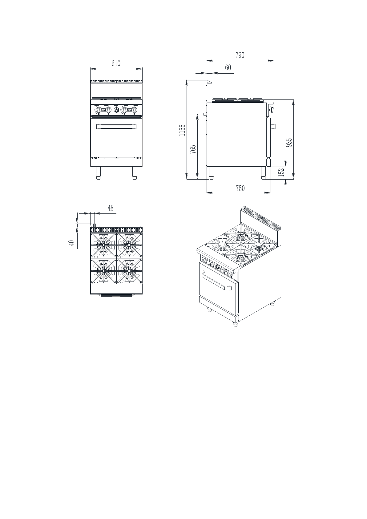
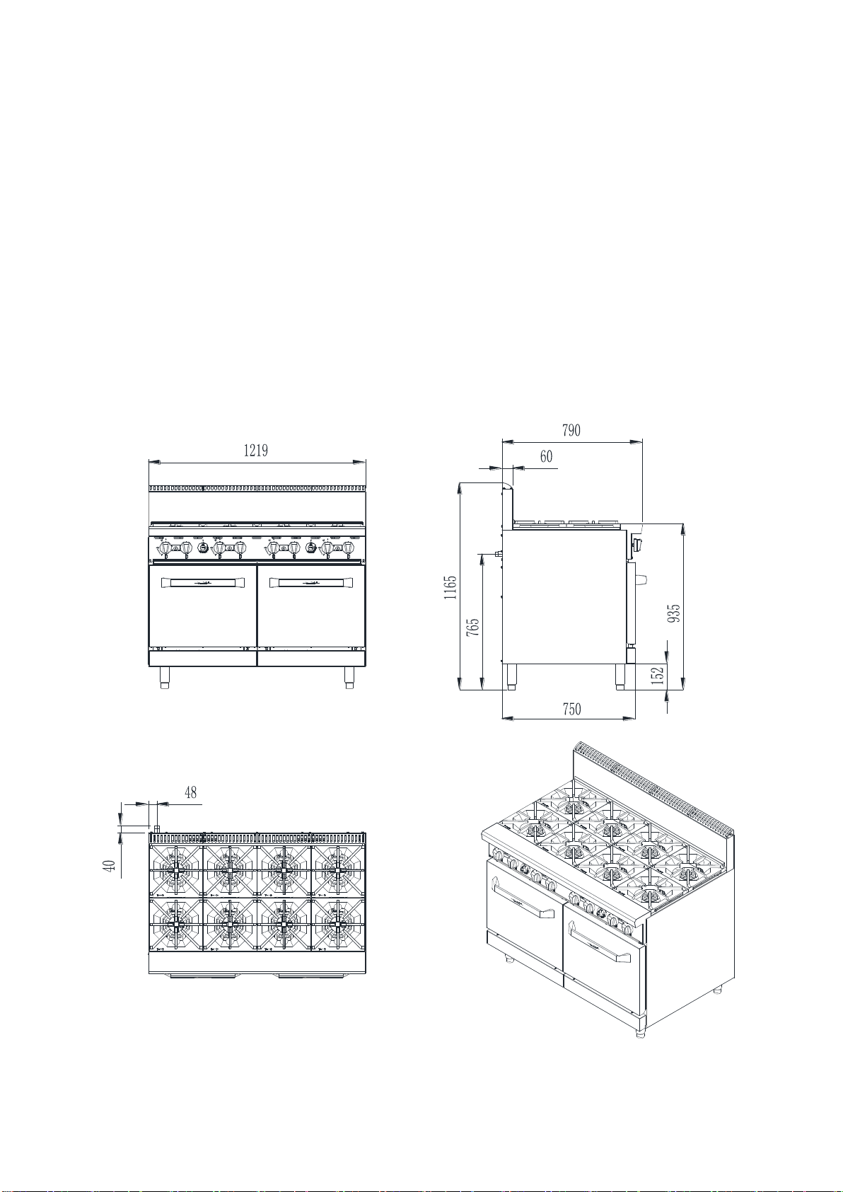
2、Brief Instruction
Such product is the gas restaurant ranges connected with oven and hot
plate manufactured by us. The product is in novel design, reasonable
structure, durable and easy to operate and maintain. The hot plate include a
cast-iron burner, and the oven include high efficiency stainless steel tubular
burners. The hot plate and the oven are equipped with a flame-out
protection device, to ensure the user’s safety in use. The oven allows for

- 4 -
constant temperature control and the user can adjust the required
temperature as required. It is an ideal cooking appliance in the industry of
hotel, supermarket, western restaurant, fast food restaurant and food.
3、Manufacture’s Authority and Responsibility
Banning of all or partial transformation to the products without the
manufacturer's explicit authorization.
Manufacturers refused to undertake responsibility to third parties
as the following reasons:
Not follow this instruction guidance and warning in in using and
testing;
Not in accordance with the requirements of technical parameters
using this product;
Incorrectly or irrationally using the product by untrained personnel;
Not obey the local law using this product;
Be repaired or changed by unauthorized technicians;
Use the spare parts or accessories provided by non-manufacturers;
Accidents caused by force majeure;
Not strictly comply with related guide of this instruction by any
reason.
4、Parameter Specifications
4.1、Outline Dimensions(mm)
ATO-4B-F

- 5 -
ATO-6B-F

- 6 -

- 7 -
ATO-8B-F
4.2:Size and package parameter information

- 8 -
<Table 1>
Model
Overall
dimensions
L x W x H
Packing size
L x W x H
Oven
dimensions
L x W x H
Numb
er of
oven
ATO-4B-F
610*790*116
5
675*990*1050
508*660*35
6
1
ATO-6B-F
914*790*116
5
980*990*1050
673*660*35
6
1
ATO-8B-F
1219*790*1165
1285*990*1050
508*660*35
6
2
4.3:Information of Gas Supply and Burner
The minimum supplied gas pressure regulator is factory set at 1.13kPa for
Natural Gas and 2.75kPa for L.P. Gas. The external thread of product’s
intake-tube is 3/4 inches.
<Table 2>
Model
Gas Species
and Intake
manifold
pressure
(kPa)
Nozzle No.
(mm)
Per rate
(MJ/h)
Number of
burners
Total rate
(MJ/h)
Hot
plates
Ove
n
Hot
plates
Ove
n
Hot
plates
Oven
ATO-4B-
Natural
1
2.1
2.4
21
26
4
1
110

- 9 -
F
Gas
L.P. Gas
2.5
1.3
1.5
ULPG
2.5
1.3
1.5
ATO-6B-
F
Natural
Gas
1
2.1
2.7
21
30
6
1
156
L.P. Gas
2.5
1.3
1.6
ULPG
2.5
1.3
1.6
ATO-8B-
F
Natural
Gas
1
2.1
2.4
21
26
8
2
220
L.P. Gas
2.5
1.3
1.5
ULPG
2.5
1.3
1.5
Gas Connection:
NOTE: ALL GAS FITTING MUST ONLY BE CARRIED OUT BY AN
AUTHORISED PERSON.
The appliances do not require an electrical connection, as they
function totally on the gas supply only.
It is essential that the gas supply is correct for the appliance to be
installed and that adequate supply pressure and volume are available.
The following checks should therefore be made before installation:
Gas Type required for the appliance is shown in the rating label.
Check that this is correct for the gas supply the appliance is being
installed for. The gas conversion procedure is detailed in this manual.
Supply Pressure required for this appliance is shown in the ‘Gas
supply requirements’ section of this manual. Check the gas supply to
ensure adequate supply pressure exists.
Input Rate of this appliance is stated on the Rating label .The input
rate should be checked against the available gas supply line capacity.

- 10 -
Particular note should be taken if the appliance is being added to an
existing installation.
NOTE: It is important that adequately sized piping runs directly to the
connection joint on the appliance with as few tees and elbows as possible to
give maximum supply volume.
NOTE: Ensure the regulator is converted to the correct gas type that the
appliance will operate on. The regulator outlet pressure is fixed
ex-factory for the gas type .
1. Correctly locate the appliance into its final operating position and using
a spirit level, adjust the legs so that the unit is level and at the correct
height.
2. Connect the gas supply to the appliance through the regulator. A
suitable jointing compound which resists the breakdown action of
propane must be used on every gas line connection, unless compression
fittings are used.
3. Check all gas connections for leakages.
4. Check that the gas operating pressure.
5. Turn off the mains gas supply and bleed the gas out of the appliance gas
lines.
6. Turn on the gas supply and the appliance.
Verify the operating pressure remains correct
5. Transport and Storage
In the process of transportation, handle carefully and keep upright to
prevent damage of the product packing. Wrapped equipment should not be
in open air for a long time, and shall be placed in a well-ventilated and
non-corrosive gases warehouse. When equipment needs temporary storage,
rainproof measures should be taken.
6. Installation and Debugging
Any erroneous installation, adjustment, refit, overhaul or
maintenance may cause property damage or personal injury. The work
shall be performed by authorized and licensed technicians, otherwise
the manufacturer has the right not to provide warranty service;
Only be installed in accordance with AS 5601/AG601, the local gas,
electricity and other relevant codes.
6.1、Unpacking and Installation

- 11 -
Please dispose of all packaging materials and residues after unpacking;
Check the equipment. If it is damaged, please keep wrappers and
receipts which must be signed by the carrier representative (Driver), and
contact the carriers to pursue a claim within 15 days after receiving;
Be sure to install supporting legs before using, and do not tear up any
label or logo before normal using;
Please read these instructions carefully before installation and operation.
Please contact your local agent if you have any questions;
Such stove shall be installed on the horizontal, solid, anti-skidding and
incombustible floor, and at the water-proof working area with sufficient
light and far away from the children and customers;
The installation position is a well-ventilated place in accordance with the
local regulations;
The charbroiled must be installed under the matched cooking fume
exhauster according to the local regulations;
Important: Installation and ventilation laws, and codes are very
different, you should state and comply with all codes of the local
competent departments when it comes to requirements for installation
of equipment;
Screw 4 adjustable stainless steel legs in the tapping hole with four
corners of the charbroiled bottom, ensure sufficient space for ventilation;
Adjustable stainless steel legs to make the equipment level, and get the
same level with other series of the same stove; Please lift the equipment
rather than drag if you need to move it;
Please refer to P19“11. Schematic Diagram for Installation of
Chimney” for the installation methods of Chimney.
Supplied gas pressure regulator is factory set at 1kPa for Natural Gas
and 2.5kPa for L.P. Gas;
The equipment can only be placed on the noncombustible floor,and
keep a distance of at least 6 inches(152mm) to equipment’s both sides 、
back and bottom,and keep a distance of at least 59 inches(1500mm) to the
top;
Do not put anything around the equipment, and on the counter top and

- 12 -
bottom, in order to avoid influencing combustion and air circulation;
Leave enough distance in front of the equipment to take apart the
control panel. All major parts, in addition to the burner remove from the
front intake-tube;
It may be necessary to adjust the balance of air input by authorized and
licensed technicians;
Thread glue must be resistant to the action of liquefied petroleum
gases.
Warning! Use soap water or testing instrument to test whether
piping joint leaks or not before using, and forbid using an open flame to
test!
After installing completely, you should check gas supply pressure. Use a
pressure gauge which is equipped with liquid (such as U-type pressure
gauge, the minimum value is 0.1mbar) or a digital pressure gauge to test.
Steps are as following:
●Remove top panel, and needle type pressure joint screw arbor (Fig.1),
then slip rubber tube of pressure gauge
over needle type pressure joint;
●Start the equipment in accordance with
the instructions, measuring gas supply
pressure (dynamic pressure) in the work
state;
●Access to the equipment if measured
data within the limits of Table 2,
otherwise, you will need to adjust gas
pressure regulating valve or contact gas
supplier to bargain;
●Unplug pressure gauge after you accomplish pressure testing, then
install needle type pressure joint screw arbor. Important: must screw
joint screw arbor, to prevent gas escape!
Ensure the pressure and no leaks of the appliance, Check the appliance
shall operate normally without flame lift or light back.
Figure 1

- 13 -
6.2 Debugging
It’s very important to debug the new stove. Through the
comprehensive system test of equipment, we can ensure function and
safety performance of products. Discovering any potential problems before
use (such as equipment’s placement, ventilation, operation, etc), can avoid
costly losses.
It is necessary to check the machine daily.
Check the machine regularly can avoid serious accident happens.
Stop using if user feels that there are some problems in the circuit or
machine.
Check the situation of the machine before or after using every day.
Before using: Whether the machine is tilted?
Whether the control panel is damaged?
During using: Whether there is strange odor or vibration noise?
Whether the burner flame is normal? Any light back or flameout?
Whether the power is normal?
If any of this case occurs, stop using and turn off gas supply, contact the
supplier or service department.
7. Safety Notices and Precautions
Warning! For your safety, do not place petrol and other flammables
nearby. Please keep clean and free of flammables surroundings.

- 14 -
Warning! Any erroneous installation, adjustment and refit may
cause property damage or personal injury and maintenance failure.
Read the instructions carefully before installation and using.
Warning! Operation instruction must be placed in a conspicuous
location. When customers smell gas in the process of using, should take
safety precautions immediately. Immediately turn off the main gas valve,
extinguish all heat and flames, and call 911. Safety information can be
obtained from your local gas suppliers.
DO NOT SPRAY AEROSOLS IN THE VICINITY OF THIS APPLIANCE
WHILE IT IS IN OPERATION.
When using this equipment, safety precautions should
always be followed, including the following:
The grates of the Hot plates, stove frame and external surface will still be
scalding after being used. You must take care when touching these
positions;
Do not directly touch the grates and stove frame when the gas
restaurant ranges is operating;
Turn off the equipment as repairing, maintaining and cleaning;
If the equipment has any problems of equipment damage, gas piping
leaks, igniter or valves damage, or lose product accessories, do not operate,
and call for the service immediately;
The use of attachments not recommended or sold by the manufacturer
may cause fire, personal injury or even death;
Do not use out of doors;
Such appliance is used to cook and bake the food and shall not be used
for other purposes;
The equipment does not contain any user-serviceable parts. Dealers or
technicians will repair it. Do not take apart any spare parts without
authorization;
Never change any other parts without authorization to this equipment,

- 15 -
otherwise, may cause hazards, and the manufacturer has the right not to
provide warranty service;
Steel cutting producers used to manufacture with sharp edges. The
manufacturer has dealt with these sharp edges during production, however,
we insist the operator take care when in contact with this piece of
equipment;
Always keep hands, hair and clothing away from heating source.
Wait the unit cools down before cleaning. Because the unit is too hot to
handle after using.
8. Operating Instructions
Before operating, make sure to place the unit horizontally by adjusting
bottom adjustable legs, and place the catch tray properly.
To ensure that the air flow in the bottom of the equipment.
Do not use fan or air-conditioning blowing at the flame, in order to
avoid extinguishing flame and cause safety accidents;
Must be installed the matched exhaust hood according to the local
regulations above the equipment.
To ensure that the air in the kitchen is kept in circulation.
The pilot light has been set at the factory. Each burner has a pilot light.
8.1 Lighting the fire(hot plates)
①、Align the control valve knob on the "O" position (Fig.2), so that the valve is
closed.
②、And then axial press the front air valve knob, left 30 degrees, to the fire
position (Fig.3).
③、At the fire position, completely press the knob, meanwhile light the fire
by pilot with another hand. Keep pressing the knob about 10-15 seconds,
and observe stability of fire.
④、If the fire is not lit, please repeat the above steps until the fire is ignited.
Tip :The pilot light may not be lighted immediately, for existing gas in

- 16 -
the pipe. Wait a minute, the pilot light will be lighted after the gas
extinguished.
8.2 Igniting the main burner(hot plates)
Revolve the main fire control valve knob anticlockwise after lighting the
pilot light, and then the main fire burner is ignited by the pilot light. When
knob reaches to " " (90 degrees), burner is in the maximum power (Fig.4).
Once again axial press the knob and revolve it anticlockwise, the power of
burner reduces gradually with the rotation angle increases. When knob is
rotated 150 degrees to " ", burner is working with a minimum power
(Fig.5).
8.3 Lighting the fire(oven)
①、Align the OFF indicative line of thermostat valve
knob to the arrow (Figure 6) to close the valve.
②、Open the underside face plate of oven (figure 7),
thoroughly press the button at the front end of
safety valve, and press the button of the piezo igniter with
another hand simultaneously (figure 8 and figure 9). there
is electric spark between pilot and fire needle. If the fire is not lit, please
Figure 6
Figure 2
Figure 3
Figure 4
Figure 5

- 17 -
repeat this action until the fire is ignited, and observe stability of fire.
Tip :The pilot light may not be lighted immediately, for existing gas in the
pipe. Wait a minute, the pilot light will be lighted after the gas extinguished.
8.4 Igniting the main burner(oven)
After the normally fire was ignited, the main fire
valve of safety valve was opened ,and press
the thermostat valve knob to rotate to the
position LOW counterclockwise (figure 10).
At this moment, the oven burner is ignited.
Rotate the thermostat valve knob
counterclockwise continuously to the required
temperature (figure 11) and the oven starts
warming. When reaching the set temperature, the thermostat valve will automatically adjust
the gas flow to keep the temperature in the oven constant.
8.5 Turn off the valve
1、Hot plates
①When the control knob is rotated to the fire position (Fig.3), the main
fire burner flame is extinguished, but the pilot light will continue to work.
Figure 7
Figure 8
Figure 9
Figure 10
Figure 11

- 18 -
②Axial press the knob to rotate knob clockwise continually, so that the
direction of the knob on the "O" position, at this time, the fire extinguished,
the valve closed.
2、Oven
Revolve the control valve knob clockwise to "0" (Fig.6), so that
extinguish flame of the main burner, but the pilot light still works.
After turn off the equipment, the main fire should be stop more than 5
minutes before next use.
8.6 Stove Operation
Before using the stove for the first time, please use a mild detergent to
wipe it clean. Do not use corrosive or abrasives detergent.
Turn the burners on about 15-20 minutes before broiling for
preheating, according to the cooking requirement to adjust the flame size.
Notice: When first preheating, the furnace will smoke above. This is
caused by protective lipids on the grates and other parts are heated, it is
normal, and it will be eliminated after the power up to the maximum for
burning an hour.
8.7 Adjust air input
①Hot plates:Remove the cooking grates, take out burner, adjust an
appropriate opening degree according to the need, then tighten the
damper fastening screws, to ensure the equipment will not get loose in the
process of moving and translation. Reinstall burner and the cooking
grates.
②: Oven: Open the underside face plate of oven (figure 7), loosen the
fastening screws of damper(figure
12) and rotate the damper
horizontally (figure 13). Meanwhile,
observe the flame. Adjust the
damper to the appropriate opening
angle. Then, tighten the fastening
screw bolt of damper to guarantee
Figure 12
Figure 13

- 19 -
the appliance does not get loose. At last, reinstall the underside face plate
of oven.
Caution: Each burner damper has been adjusted before delivery
(once air input), Normal use without adjustment but only switching
gas. Adjust only by authorized and licensed technicians.
8.8 Exchange the pilot assemblies and the nozzle to switch gas source
①Hot plates:Remove the cooking grates, take out burner, and then
remove the pilot assemblies and main fire nozzle with a wrench, exchange
the other gas of the main fire nozzle (Fig.14) and the pilot orifice (Fig.15),
then screw it. Reinstall burner and the cooking grates.
②:Oven: Remove the door, floor, radiant panel, open the bottom plate,
remove the screw at the end of burner, take off the burner, and then remove
the pilot assemblies and main fire nozzle with a wrench, exchange the other
gas of the main fire nozzle (Fig.16) and the pilot orifice (Fig.17),then tighten
the wrench. And then install back the radiation board, floor, door and install
the panel.
Fig.14 Fig.15
Fig.16 Fig.17
This manual suits for next models
2
Table of contents
Other Atosa Range manuals
Popular Range manuals by other brands

Amana
Amana AGR3311WD installation instructions

Frigidaire
Frigidaire FGF379WECK Factory parts catalog

Verona
Verona Prestige VPFSEE365SS installation instructions

LG
LG LRG5115 Series owner's manual

Frigidaire
Frigidaire FFEF3018LB Specification & installation instructions

Maytag
Maytag Precision Touch Control 800 Use & care guide