ATS MC22LV Series User manual

MC22LV SERIES
MASTER CLOCKS
FN:MC22LV-M1.DOC

MC22LV SERIES –MASTER CLOCKS
REV 3/17/15
APPLIED TECHNICAL SYSTEMS PAGE 1
TABLE OF CONTENTS
1.0 INTRODUCTION
2.0 SPECIFICATIONS
3.0 INSTALLATION
4.0 GETTING STARTED
4.1 The Auto-Prompt Display
4.2 The Cursor, Entering Data
4.3 Applying Power, Entering Time
4.4 Entering the Date
4.5 Entering the Day
4.6 Daylight Savings Time
4.7 Entering Pulse for Relays 1 and 2
4.8 Basic Plan
5.0 OPERATION
5.1 Editing Time
5.2 Reviewing or Editing Date
5.3 Reviewing or Editing Day
5.4 Reviewing or Editing Daylight Savings Time
5.5 Reviewing or Editing the Relay Pulse for Relays 1 and 2
5.6 Reviewing or Editing the Basic Plan Program
6.0 PROGRAMMING
6.1 Entering the Basic Plan Program
6.2 Clearing a Program Step
6.3 Entering, Reviewing or Editing the Annual Program
6.4 Clearing an Annual Plan
6.5 Clearing the Annual and Basic Programs
7.0 SPECIAL FUNCTIONS
7.1 Manual Operation of the Output Relays
7.2 Manual Selection of Alternate Plans
7.3 Setting the Maximum Number of Steps Per Plan
7.4 Enter Sleep Mode
7.5 Status
7.6 Forcing a Restart
7.7 Software Version
7.8 Selecting the Time Base
8.0 ADVANCED PROGRAMMING
8.1 Custom Weeks
8.2 Annual Repeat Programs
8.3 RS232 I/O Interface
8.4 Select 12 or 24 Hour Clock Output
PROGRAMMING SUMMARY
The MC22LV is a two-circuit master clock. This manual will use the "MC22LV" and the "Master
Clock" interchangeably.

MC22LV SERIES –MASTER CLOCKS
REV 3/17/15
APPLIED TECHNICAL SYSTEMS PAGE 2
1.0 INTRODUCTION
The MC22LV is a two circuit, calendar programmable solid state master clock. It is used for
switching low voltage electric circuits according to a preset time and date program. The
MC22LV's AUTO PROMPTING, alphanumeric display makes programming fast and simple. The
output relays can be used to ring bells, to control audio/visual equipment or to control lighting,
heating, ventilating, air conditioning and security systems with a variety of programming
capabilities, ranging from a simple 7 day plan to a more complex plan utilizing its powerful,
alternate annual programming features. Each has a compact wall mount enclosure. Selected
outputs can be independently programmed for momentary operation such as required for ringing
bells in schools, churches or industrial facilities.
Limited options are available for the MC22LV master clocks.

MC22LV SERIES –MASTER CLOCKS
REV 3/17/15
APPLIED TECHNICAL SYSTEMS PAGE 3
2.0 SPECIFICATIONS
PROGRAMMING CAPABILITIES
Auto Prompting Display - Provides display information to guide the operator during programming.
From a restart it will take the operator from setting time clear through setting the basic program
steps.
200 Powerful Program Steps - The MC22LV has a default set up of 1 Basic 7 day plan and 9
Alternate 7 day plans that can be scheduled on an annual basis, or keyboard selected for the
current day. The default setup provides for a total of 10 plans, each having 20 program steps. If
more than 20-program steps are needed, the program size can be increased using a keyboard-
entered function. Up to 100 steps per plan can be programmed for a total of 2 plans. 50 steps
per plan would provide a total of 4 plans. Each step can be programmed for both or any
combination of the output relays for a specific day of the week, or for all 5 weekdays, or for both
weekend days, or for everyday of the week. In addition, steps can be programmed in customized
groups such as, Monday, Wednesday, and Friday only.
20 Annual Plans - Each annual plan has a starting and ending date, and an associated Alternate
Plan. This feature can be used to schedule any 1 of the 1 to 9 alternate, 7 day plans to be used by
the MC22LV. Certain annual plans can be programmed to repeat on a yearly basis so that they
don’t have to be reprogrammed each year.
Sleep Mode –Entering Sleep Mode suspends program operation (all program steps are ignored).
Leaving Sleep Mode, the program resumes at the next scheduled program step.
Programmable Daylight Savings Time Adjustment - The MC22LV can be programmed to
automatically adjust its time for Daylight savings time changes according to U. S. law, even if the
law changes.
Automatic Leap Year Compensation.
Manual Override - The output relays can be manually energized or de-energized from the
keyboard. The word “Manual” replaces the word “Relays” in the time display until the next program
step occurs.
Pulsed Output –Relays 1 and 2 can be programmed individually or as a group to operate as
momentary contacts, programmable from 1 to 9 seconds.
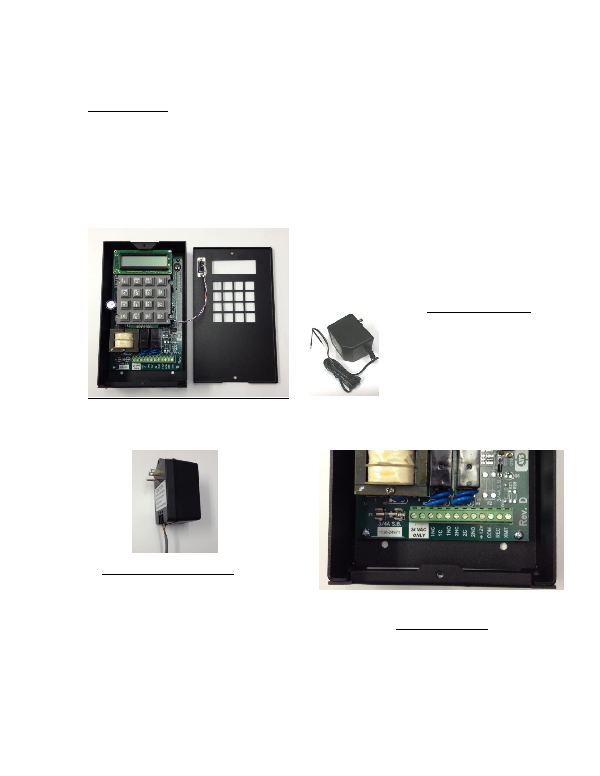
I/O Port –An RS232 I/O port provides an interface for connecting to a computer, or to other ATS
devices such as: Digital Clocks, GPS Systems, Ethernet Interface, and other compatible serial
data products. The RS232 I/O port is provided on the front panel with a DB9 female connector,
and on the terminal blocks inside the enclosure.

MC22LV SERIES –MASTER CLOCKS
REV 3/17/15
APPLIED TECHNICAL SYSTEMS PAGE 4
ELECTRICAL
Power: Standard power required is from 20 VAC to 28 VAC, 60 HZ at 8 VA
maximum. A Power Module is provided with 120 VAC input to 24 VAC
500mA output. An optional larger 1.66 Amp Power Module is available
for powering some add-on accessories. Contact the factory for details.
Outputs: MC22LV - Two relays (SPDT) rated at 15A, 48 VAC or 24 VDC resistive.
RS232 I/O: For connecting to a computer, or to other ATS devices such as: Digital
Clocks, GPS Systems, Ethernet Interface, and other compatible serial
data products.
Wiring: A clearly labeled terminal block is provided inside the MC22LV.
.
POWER FAIL BACKUP
Non-Volatile Memory keeps time and programs for indefinite power outages. All outputs and the
display are disabled during backup. The MC22LV resumes normal operation when power returns.
If the master clock has been without power for more than 48 hours a “Unit Power Fail” message
will appear when power is restored. Times and program will be intact, however pressing the [3]
key will begin the AUTO PROMPT sequence. Check time, date, day, etc. to insure accuracy, then
press the [EXIT].
ACCURACY
Time Keeping - Synchronous with the AC power line. During a power failure, or when crystal time
base is selected, timekeeping is crystal controlled with an accuracy of +/- 4 PPM throughout its full
temperature range.
Programmed Events - On/Off events are programmable with a one-minute resolution and occur
at the zero second of that minute.
Operating Temperature Range - 0 to 50 degrees C
PHYSICAL
MC22LV: Black, painted aluminum enclosure - 4.8"W X 8"H X 1.8"D.
Mounting holes are provided in the enclosures for easy installation.

MC22LV SERIES –MASTER CLOCKS
REV 3/17/15
APPLIED TECHNICAL SYSTEMS PAGE 5
FRONT PANEL DESCRIPTION
ALPHANUMERIC DISPLAY - Used for displaying time, day, date, and output status, and for
displaying information during programming or reviewing stored programs. In the normal mode of
operation, the display will be in the TIME DISPLAY, showing the day, time, and which relays are
activated.
KEYBOARD - Many keys serve multiple functions. Those keys are clearly labeled with their
functions to the side and top of the key. They cannot be used incorrectly, as the display will
AUTO PROMPT the user as to which key to press.
AM ON KEY [1] - Used for setting the time to AM when in the TIME SET or PROGRAMMING
MODES and for entering the MANUAL CONTROL MODE.
PM KEY [2] - Used for setting the time to PM when in the TIME SET or PROGRAMMING
MODES.
TIME KEY [3] - Used for entering the TIME SET MODE.
ANNUAL KEY [A] - Used for entering the ANNUAL PROGRAMMING MODE and for stepping
through the stored ANNUAL PLAN for review. The ANNUAL PLAN contains the schedule for the
alternate BASIC PLANS in calendar schedule form.
BASIC KEY [B] - Used for entering the BASIC PLAN - PROGRAMMING MODE and for stepping
through the stored BASIC PLANS for review. The BASIC PLANS contain the daily timed events
instructions.
CLEAR KEY [C] - Used for clearing the ANNUAL PLAN and/or BASIC PLANS.
DATE KEY [D] - Used for entering the SET DATE MODE for entering date or reviewing the date.
EXIT KEY [#] - Used for exiting any of the SET TIME, SET DATE or PROGRAM MODES.
OFF KEY [0] - Used for setting the pulse to OFF when in the PULSE PROGRAMMING MODE.
ENTER KEY [*] - Used for entering all commands or for stepping through any SET TIME, SET
DATE or PROGRAM data entry.
DST KEY [7] - Used for entering the SET DAYLIGHT SAVINGS TIME PROGRAM MODE.
DAY KEY [4] - Used for setting the day in the SET DAY and PROGRAM MODES. Also used for
entering the SET DAY MODE.
.

MC22LV SERIES –MASTER CLOCKS
REV 3/17/15
APPLIED TECHNICAL SYSTEMS PAGE 6
3.0 INSTALLATION
MC22LV SERIES
The MC22LV should be securely mounted to a suitable mounting panel or surface according to
any local codes using the mounting holes provided. Be sure the equipment is properly grounded
to the panel or the facilities ground connection.
ELECTRICAL CONNECTIONS
All wiring connections are made at the clearly marked terminal block located on the inside of the
MC22LV enclosure, Remove the top cover of the MC22LV to gain access to the terminal block.
MC22LV shown with the top cover removed.
A 120 VAC to 24 VAC
Power Module is provided.
Connects to the MC22LV
Terminals labeled 24 VAC ONLY.
Clearly labeled terminal block is provided
for all field wiring.
Standard Power Module
Optional Larger Power Module
An optional, larger Power Module is
available for powering accessories.
The 0900-7084 provides
24 VAC at 1.67 Amps.
This Power Module is standard on the
MC22-BH and MC22-BP
Series products
Terminal Block Detail

MC22LV SERIES –MASTER CLOCKS
REV 3/17/15
APPLIED TECHNICAL SYSTEMS PAGE 7
OPTIONS
There are a variety of options available for the MC22LV. For details on the installation and
operation of the installed option, refer to the Addenda for those options at the back of this manual.
4.0 GETTING STARTED
4.1 THE AUTO PROMPT DISPLAY
The master clock has a feature called Auto Prompt that guides the operator when programming
the unit. For the most part the operator merely has to follow the display as the master clock
advances through the Program Modes. On a restart (from a “power fail” condition) the master
clock will advance through a sequence of all the necessary settings including the Basic Plans. You
may exit this sequence if desired and enter the program manually from the time display, using the
specific commands. Entering a program from the Auto Prompt sequence is identical to entering
one manually.
4.2 THE CURSOR, ENTERING DATA
On many of the display messages you will see a flashing square character called the cursor. The
cursor indicates that you may now enter or change the data at that position of the display. As data
is entered the master clock constantly checks for a valid entry. For example, you cannot enter 13
for a month when setting the date. After entering valid data to a position on the display, the
cursor will advance to the next position. If you have tried to enter invalid data, the cursor will
remain at the same position, indicating you must re-enter the data. Simply re-enter the data on
top of the existing data and press [ENTER]. Generally, data is entered two digits at a time and
shifts left with each entry.
4.3 APPLYING POWER, ENTERING THE TIME
Before power is applied, be sure all installation and wiring is completed to all local codes.
Upon first applying power the display will come up with a brief sign on message showing the
model and version numbers:
After a few seconds the first Auto Prompt message will appear. If the following message does not
appear, read section 7.6 FORCING A RESTART.
Simply press key [3]. The display will prompt with the set time display.
MC22 Master Clk.
Version 4.XX
UNIT POWER FAIL
Press “3” key
Time? 00:00 AM
Hrs. (HH), ENTER

MC22LV SERIES –MASTER CLOCKS
REV 3/17/15
APPLIED TECHNICAL SYSTEMS PAGE 8
It may be showing the correct time, some other time, or all “0’s”.
From this point forward you can exit the Auto Prompt sequence at any time, if desired, by pressing
[EXIT]. However, the programming is simplified by staying in the Auto Prompt mode. On a restart
all program memory is cleared in the master clock. The cursor will be flashing in the hour’s digits.
The bottom line is a prompt to enter 2 digits (HH) for hours. Enter the hours then press the
[ENTER] key. Two digits are required for the hours. Example: 01 instead of 1. The cursor will
remain flashing in the hour’s digits if an invalid number is entered for the hours. Enter the correct
hours. Once a valid number is entered for the hours, the cursor will advance to the minute’s
digits. Again, the bottom line is a prompt for entering the minutes. Type two digits for the minutes
and press [ENTER]. The cursor will advance to the AM position. Press the AM or PM key then
press [ENTER]. Time keeping begins the instant you press [ENTER]. Time can be accurately
set to the second by pressing the [ENTER] key at the desired instant.
4.4 ENTERING THE DATE
The next step in the AUTO-PROMPT sequence is entering the date. The display will show:
It may be showing the correct date, some other date, or all “0’s”.
The cursor will be flashing in the month's position. The bottom line will give you additional
information on how to enter the data. Type the two digit number for the month and press
[ENTER]. If the correct two digits are already there, simply press [ENTER]. The cursor will move
to the day position. Type the two digits for the day and press [ENTER]. The cursor will move to
the year position. Type the two digits for the year and press [ENTER].
4.5 ENTERING THE DAY
Next, we enter the day of the week. The display will show:
It may be showing the correct day or some other day stored previously. Press the DAY key [4]
until the desired day is shown on the display and then press [ENTER].
4.6 DAYLIGHT SAVINGS TIME
The default entries for daylight savings time according to current U.S. law will display as follows:
The master clock is pre-loaded with the current daylight savings time settings according to
U.S. law. Unless the law changes or you live in an area that does not follow standard U.S.
daylight savings time there is no need to change anything on the DST screen. The top line
Date? 12-29-15
Month (MM), ENTER
Day? Sun
DAY key, ENTER
S DST M=03 SUN=2
F DST M=11 SUN=1

MC22LV SERIES –MASTER CLOCKS
REV 3/17/15
APPLIED TECHNICAL SYSTEMS PAGE 9
is for the Spring DST and the bottom line is for the Fall DST. The S indicates the Spring DST and
the F indicates the Fall DST. The cursor will be flashing in the month position. Enter the two
digits for the month in which you wish the Spring DST adjustment to be made (03 for current US
law), then press [ENTER]. The valid Spring months are 00, 03, 04, and 05. Enter 00 for the
month if you do not wish to use the automatic DST feature and the master clock will advance to
the next Auto Prompt display. After a valid month is entered, the cursor will advance to the L in
the Sunday position. Enter a 2 for the second Sunday (current US law), 2 for the second, 3 for the
third, 4 for the fourth or L for the last Sunday. Use the [5] key to enter the L. The change will be
made at 02:00 AM on the Sunday you choose.
After the Spring DST data is entered, the cursor will advance to the Fall DST line. If you have
entered a Spring DST, you must enter a Fall DST as well. Failure to do so will erase the Spring
DST and then there will be no DST compensation.
Fall DST is entered in the same manner as the Spring DST. Current US law for Fall DST is the
first Sunday in November. Enter 11 for the month and 1 for the Sunday. The valid months for
the Fall DST are 09, 10, and 11. The valid Sundays for the Fall DST are 1, 2, 3, 4 and L. Use the
[5] key to enter the L. The change will be made at 02:00 AM on the Sunday you choose.
4.7 ENTERING PULSE (MOMENTARY OUTPUT) FOR RELAYS 1and 2
The pulse for each relay is preset to 5 seconds for momentary ON/OFF events such as ringing
school bells, or factory break buzzers. It can be changed as desired for up to 9 seconds duration.
A second momentary output of a different duration may be required for late bells or warning bells.
The cursor will be flashing on the "5" for Relay 1. Enter the duration for Relay 1 from 0 to 9
seconds, Press [ENTER]. 0 = Pulse OFF. The cursor will then be flashing on the "5" for Relay 2.
Enter the duration for Relay 2 from 0 to 9 seconds, Press [ENTER]. 0 = Pulse OFF.
For applications requiring steady ON and OFF events, the pulse can be set to OFF for either or
both relays as shown below. If a relay is turned ON with a PULSE SETTING = to OFF, the
relay will stay ON until programmed to turn OFF again with another program step.
The master clock will advance to the next Auto Prompt display.
R1 Pulse= 5 Sec
R2 Pulse= 5 Sec
R1 Pulse= OFF
R2 Pulse= OFF
R1 Pulse= OFF
R2 Pulse= 5 Sec

MC22LV SERIES –MASTER CLOCKS
REV 3/17/15
APPLIED TECHNICAL SYSTEMS PAGE 10
4.8 BASIC PLAN
The next step of the AUTO-PROMPT sequence is basic plan programming. Refer to Chapter 6.0
PROGRAMMING for details on entering your basic plan.
Note: Setting Annuals is not included in the auto prompt sequence. See ENTERING,
REVIEWING OR EDITING THE ANNUAL PROGRAM(Section 6.3).
5.0 OPERATION
This section will explain how to change or review the existing time, date or programs previously
stored, how or how to totally program the unit after exiting the AUTO-PROMPT sequence. It
describes how to manually invoke each mode from the command line. You must be in the time
display before you can enter a command. Press the [EXIT] key to be sure. The display should
look similar to the following:
5.1 EDITING TIME [3] [ENTER]
Press the TIME key [3]. The display will respond with:
Press [ENTER]. The display will respond with:
Now you may enter the time as you would during the AUTO-PROMPT sequence. (see Section
4.3 APPLYING POWER, ENTERING THE TIME)
5.2 REVIEWING OR EDITING THE DATE [D] [ENTER]
You must be in the time display in order to enter the date. Press the DATE key [D]. The display
will respond with:
Press [ENTER]. The display will respond with:
Enter the date as described in Section 4.4 ENTERING THE DATE.
Command? 03
Press ENTER
Time? 12:34 AM
Hrs. (HH), ENTER
Command? 0D
Press ENTER
Date? 12-29-15
Month (MM), ENTER
Mon 01:18:00 PM
Relays: - -

MC22LV SERIES –MASTER CLOCKS
REV 3/17/15
APPLIED TECHNICAL SYSTEMS PAGE 11
5.3 EDITING THE DAY [4] [ENTER]
You must be in the time display. Press the DAY key [4]. The display will respond with:
Press [ENTER]. The display will respond with:
The day of the week may now be entered in the same manner as in the AUTO-PROMPT
sequence. (Section 4.5)
5.4 REVIEWING OR EDITING DAYLIGHT SAVINGS TIME [7] [ENTER]
You must be in the time display. Press the DST key [7]. The display will respond with:
Press [ENTER]. If daylight savings time not previously set, the display will respond with the
default entries for the current U.S. law as follows:
You may now enter the new daylight savings time settings as outlined in Section 4.6.
5.5 REVIEWING OR EDITING THE RELAY PULSE (MOMENTARY OUTPUTS)
FOR RELAYS 1 and 2 [5] [ENTER]
The pulse is for applications in which only a momentary contact is required (i.e. ringing bells). See
Section 4.7 for more information on pulse settings. Start from the time display. Press key [5].
The display will respond with:
Press [ENTER]. The display will respond with:
The pulse settings for relays 1 and 2 may now be set as outlined in Section 4.7. 0 = Pulse OFF
Command? 04
Press ENTER
Day? Sun
DAY key, ENTER
Command? 07
Press ENTER
S DST M=03 SUN=2
F DST M=11 SUN=1
R1 Pulse= 5 Sec
R2 Pulse= 5 Sec
Command? 05
Press [ENTER].

MC22LV SERIES –MASTER CLOCKS
REV 3/17/15
APPLIED TECHNICAL SYSTEMS PAGE 12
Once you have entered the relay pulse settings the master clock will return to the time display.
5.6 REVIEWING OR EDITING THE BASIC PLAN PROGRAM [B] [ENTER]
If the basic program was not entered during the restart Auto Prompt sequence, it can be entered
by entering the basic program mode. This mode allows the operator to program the daily timed
events. Before entering your program be sure to write it out on a program record sheet. Copies of
the program record sheet are located at the back of this manual. You may need to change the
size of your basic program if it requires more than 20 steps. See SETTING THE MAXIMUM
NUMBER OF STEPS PER PLAN (Section 7.3) for more detail.
Press BASIC [B]. The display will respond with:
The master clock will now advance to the programming sequence.
At this point you can press the [B] key repeatedly to review all stored program steps.
6.0 PROGRAMMING
6.1 ENTERING THE BASIC PLAN PROGRAM
Before you begin programming your MC22LV you should complete the MC SERIES PROGRAM
RECORD SHEET included at the back of this manual. Be sure to enter pulse lengths if required
for all relays (Sections 5.5, 5.6). You may need to change the size of your basic program. See
Section 6.3 for more detail.
See Section 5.8 for information on starting the programming sequence. The display should be
showing:
The cursor will be flashing on the zero for Plan #0. Plan #0 is the first of up to 10 Basic Plans,
each of which contains a 7-day plan. Plan #0 is the main 7 day plan and plans 1 through 9
are alternate 7 day plans. Alternate plans can be scheduled on an annual basis (more on this in
ENTERING, REVIEWING OR EDITING THE ANNUAL PROGRAM Section 6.3). Press
[ENTER] to select plan #0. The cursor moves to the Step #00 position. Step #00 is the first step
of 20 steps in plan #0 by default (Section 7.3). Press [ENTER] to select step #00 and the display
will read as follows:
Command? 0B
Press ENTER
BASIC Plan #0
Step #00

MC22LV SERIES –MASTER CLOCKS
REV 3/17/15
APPLIED TECHNICAL SYSTEMS PAGE 13
The cursor will be flashing on the W of WDY (weekday).
Step # - The #00 indicates that this is step 00 being displayed.
Day - Program steps may be programmed for individual days, such as Mon or Tue, or for groups
of days such as WDY for weekdays. See below for the step abbreviations, and what they mean.
“Special Weeks” (Wk0 thru Wk9) can be created for your specific needs. For example, a Mon,
Wed, Fri week. See ADVANCED PROGRAMMING (Section 7.1) for more details. Press the
DAY [4] key to advance to the chosen day or group of days. The display will update as you press
the DAY[4] key. Once the preferred day or group is displayed, press [ENTER]. The display will
advance to the hour’s position.
STEP DAY MEANS…
EDY step occurs everyday
WDY step occurs every weekday
WND step occurs every weekend day
MON step occurs every monday
TUE step occurs every tuesday
WED step occurs every wednesday
THU step occurs every thursday
FRI step occurs every friday
SAT step occurs every saturday
SUN step occurs every sunday
WK0-WK9 step occurs on days designated by custom week (see
Section 8.1)
Hours - Enter the two digit hour at which this step is to be activated and press [ENTER]. The
display will advance to the minute’s position.
Minutes - Enter two digits for the minutes and press [ENTER]. The display will advance to the
AM/PM position.
AM/PM - Press the [AM] [1] or [PM] [2] key, then [ENTER]. The display will advance to the first
position after the word RELAY.
Relays - Enter the number of the relays you wish to be energized by this program step. If a step
is entered and a relay that is already energized should stay energized until the next step, it is
necessary to enter the relay number again for this step. The relay settings show the state of the
relays at the programmed time of the step. The relay numbers will appear on the bottom line as
you press the appropriate number. Pressing the same number again will remove the relay number
from the bottom line. Once the relays are set, press [ENTER]. The first step (00) is programmed.
The following display shows an example of all relays being activated on Weekdays at 10:00 AM.
#00 WDY 10:00 AM
Relays: 1 2
#00 WDY 00:00 AM
Relays: - - - - - - - -
Step
#
Day
Hours
Minutes
AM/PM
Relay
s

MC22LV SERIES –MASTER CLOCKS
REV 3/17/15
APPLIED TECHNICAL SYSTEMS PAGE 14
The Auto Prompt display will advance to the next step (01).
Subsequent steps are entered the same way as the first. Continue until the last step of Basic
Plan #0 is entered. Step 19 (the 20th step) is the last step if you are using the default setting of 20
steps per plan. After entering the last step, the master clock will advance to Basic Plan #1:
The master clock is now prompting you to enter the first of up to 9 alternate plans, plan #1. Plans
1 through 9 are entered the same as plan 0. If you are not using alternate plans 1 through 9, or if
you have just entered your last alternate plan, press [EXIT]. The master clock will return to the
time display.
6.2 CLEARING A PROGRAM STEP
To clear a program step, press BASIC [B], then [ENTER].
The display will prompt you for a plan #(cursor on 0). Choose the basic plan in which the step to
be cleared is located, then press [ENTER].
The display will then prompt for a step #(cursor on 00). Choose the # of the step to be cleared,
then press [ENTER]. The chosen step and its program contents will be displayed.
The cursor will be on the first letter of the day of the week. Press [ENTER]. The cursor will go to
the hour’s position. Enter 00 for the hours. This will clear this specific step. Press [ENTER]. The
display will advance to the next step. If you are finished, press [EXIT]. The display will read:
Choose another plan to edit or press [EXIT] again to return to the time display.
If you wish to erase all the program steps see CLEARING THE ANNUAL AND BASIC
PROGRAMS (Section 6.5).
6.3 ENTERING, REVIEWING OR EDITING THE ANNUAL PROGRAM
[A] [ENTER]
The annual program allows the master clock to be programmed to select any 1 of up to 9
alternate plans. This feature is useful for applications that require a different 7-day plan at
BASIC Plan #0
Step # 00
BASIC Plan #1
Step # 00
BASIC Plan #1
Step # 00
#01 WDY 00:00 AM
Relays: - -

MC22LV SERIES –MASTER CLOCKS
REV 3/17/15
APPLIED TECHNICAL SYSTEMS PAGE 15
different times in the future. There are 20 Annual Program Plans, each of which has a starting
and ending date, and an associated, alternate plan. The selected alternate plan will begin at
12:00 AM on the start date and will end at 11:59:59 PM on the day of the end date. Basic Plan 0
takes over at the end of any Alternate Plan. To enter the annual program mode, press the
ANNUAL [A] key. The display will respond with:
Press [ENTER]. The display will respond with:
The cursor will be prompting for an Annual Plan number. #00 is the first Annual Plan. Press
[ENTER]. The cursor will then prompt for the Basic Plan to select with this Annual. Enter the
Basic Plan number, then press [ENTER]. The display will read:
There may be a date already in the start date from a previous program. It is not necessary to
erase this old date. Simply enter new data in each field. To erase an annual plan see
CLEARING AN ANNUAL PLAN (Section 6.4). The cursor will be flashing in the month’s position.
Type the two digits for the month at which this Annual Plan will start and press [ENTER]. The
display will advance to the day’s position. Type the two digits for the day and press [ENTER].
The display will advance to the years position. Type the two digits for the year and press [ENTER]
or enter [XX] to repeat the Annual program each year. See the ANNUAL REPEAT PROGRAMS
instructions in ADVANCED PROGRAMMING (Section 8.2) for details. The cursor will advance to
the end date line. Enter the end date in the same manner as the start date. If your Annual Plan
is only for one day, do not enter an end date. Just press [ENTER] to put “00” in the months and
the display will advance to the next Annual Plan.
Repeat the same procedure for Annual 01 as you did for Annual 00, or press [EXIT] to return to
the time display.
6.4 CLEARING AN ANNUAL PLAN
To clear an Annual Plan, press the ANNUAL [A] key, then [ENTER]. The display will respond
with:
Enter the Annual Plan number to be cleared and press [ENTER] twice. The display will show the
contents of that Annual Plan.
Command? 0A
Press ENTER
ANNUAL #00
BASIC #1
Start? 00-00-00
End? 00-00-00
ANNUAL #01
BASIC #1
ANNUAL #00
BASIC #1
Start? 12-19-15
End? 01-01-16

MC22LV SERIES –MASTER CLOCKS
REV 3/17/15
APPLIED TECHNICAL SYSTEMS PAGE 16
Enter 00 for the Start month and press [ENTER]. The plan will be cleared. There is no need to
clear the end date once the start date has been cleared. If you are programming the clock from a
restart, the annual and basic program steps will be cleared already.
6.5 CLEARING THE ANNUAL AND BASIC PROGRAMS [C] [ENTER]
If you are re-programming a previously programmed clock you will need to erase any previous
programs as they could conflict with your new program. To clear all program steps, press the
CLEAR [C] key. The display will respond with:
Press [ENTER]. The display will respond with:
To clear the Annual program, press [A]. The display will return to the time display. To clear the
Basic program instead, press [B].
Choose a Basic Plan number to clear or press [A] to clear all Basic Plans.
If you wish to clear both the annual and basic programs, repeat the process a second time. Only
one can be cleared at a time.
7.0 SPECIAL FUNCTIONS
7.1 MANUAL OPERATION OF THE OUTPUT RELAYS [1] [ENTER]
WARNING!! Manually controlling the relays will affect the loads connected to the Master
Clock. Operating these loads at the wrong time may cause damage, injury or disruption of
activities. Be aware of what is being operated by the relays and let others know that this is
about to take place.
To manually control the output relays from the keyboard, press the MANUAL [1] key. The
display will respond with:
Press [ENTER]. The display will respond with:
Command? 0C
Press ENTER
Clear buffers:
A=ANNUAL B=BASIC
Press 0-9 or “A”
for all sets
Command? 01
Press ENTER
Manual Control
Relays: - -

MC22LV SERIES –MASTER CLOCKS
REV 3/17/15
APPLIED TECHNICAL SYSTEMS PAGE 17
Key in the number(s) of the relay(s) that you would like to manually control. The numbers of the
relays chosen will be seen on the bottom line of the display. To remove a relay from the bottom
line, press its number again.
After selecting the relays, press [ENTER]. The output relays chosen will be energized and the
Master Clock will return to the time display. The relays will remain on for the duration of their
respective pulse length, or until the next program step instructs them to turn off, or until they are
manually operated again.
7.2 MANUAL SELECTION OF ALTERNATE PLANS [2] [1] [ENTER]
Alternate Plans can be selected from the keyboard in addition to being selected by the ANNUAL
PROGRAM.
To select an Alternate Plan type [2] [1] [ENTER]. The display will respond with:
Enter the desired Basic Plan number, then press [ENTER]. The master clock will now run the
Basic Plan you have selected. The master clock will automatically go back to Basic Plan 0 after
12:00 AM. Also, if any of the following changes are made, the master clock will return to Basic
Plan 0:
Entering a new time.
A power failure of any duration.
Entering a new date.
Modifying the Annual programs.
Clearing the Annual programs.
Use special function 90 (See STATUS Section 7.5) to verify which plan is running.
7.3 SETTING THE MAXIMUM NUMBER OF STEPS PER PLAN [3] [1]
[ENTER]
The master clock has a default setup of 10 Basic Plans with 20 Program Steps each for a total of
200 steps. These plans are numbered Plan 0 through Plan 9. Plan 0 is the main Plan that will
repeat itself every 7 days. Plans 1 through 9 are Alternate Plans that can be scheduled by the
Annual Program, or they can be called up manually using the MANUAL SELECTION function as
described above.
The master clock can be reconfigured to allow more than 20 Steps per Plan. Special function
Command 31 is used to adjust the number of Steps per Plan from 20 to 100. The number of
Alternate Plans will automatically be adjusted to fit the maximum number of 200 Steps available.
Changing the maximum number of Steps per Plan should be done prior to entering your
program.
To set the number of Steps type [3] [1] [ENTER]. The display will read:
Select
New Basic: 0
Max. Step No: 19
(0-99), ENTER
Manual Control
Relays: 12

MC22LV SERIES –MASTER CLOCKS
REV 3/17/15
APPLIED TECHNICAL SYSTEMS PAGE 18
The cursor will be flashing on the maximum Step number. Since all Step numbers begin with 0,
a maximum number of 19 represents 20 Steps. Refer to the chart below to determine your Max.
Step No
# Steps # Alternate Plans Max. Step No.
1-20 9 19 (default)
21-25 7 24
26-28 6 27
29-33 5 24
34-40 4 39
41-50 3 49
51-66 2 65
67-100 1 99
If your application requires 26 steps, enter 27 as the Max. Step No.
Press [ENTER]. The display will respond as follows:
Since the Basic Plans begin with Plan 0, this means there are a total of 7 Plans available. Each
will have 28 Steps. To go back to the time display, press [EXIT].
7.4 ENTER SLEEP MODE [4] [5] [ENTER]
Sleep Mode is useful for suspending “Break Signals” during student testing, Summer school,
meetings, and other special events.
Sleep Mode can be selected from the keyboard. Press [4] [5] [ENTER] . The display will show:
To exit the Sleep Mode, press [4] [5] [ENTER] again. The MC22LV will resume normal operation.
During “Sleep Mode” the MC22LV ignores all Basic Plan programs (relay outputs are stopped).
This does not affect any stored Basic Plans or Annual Plans.
7.5 STATUS [9] [0] [ENTER]
The master clock has a status check capability. Press [9] [0] [ENTER]. The display will show:
“T” status is for factory use only. It should always be "N". “B” status indicates which Basic Plan is
in effect. “A” status indicates which Annual Plan is in effect. “XX” indicates no Annual Plan in
use at this time. “MD” status indicates whether the MC22LV is transmitting 12 or 24 Hour time.
Unit Status: T=N
B=0 A=XX MD=12H
Max. Buffer No.
= 6 (Press EXIT)
Sleep Mode
(Command 45)

MC22LV SERIES –MASTER CLOCKS
REV 3/17/15
APPLIED TECHNICAL SYSTEMS PAGE 19
7.6 FORCING A RESTART [7] [7] [ENTER]
For training purposes or clearing all programming information from the master clock, a restart is
recommended. Press [7] [7] [ENTER]. The display will show the UNIT POWER FAIL message.
7.7 SOFTWARE VERSION [9] [9] [ENTER]
To check the version of the software installed in your master clock press [9] [9] [ENTER]. The
display will read:
After 5 seconds the display will return to the time display.
7.8 SELECTING THE TIME BASE [3] [0] [ENTER]
The default Time Base setting for the MC4181LV is for 60 HZ AC line synchronization. This is the
preferred setting for installations in North America and other countries where 60 HZ power is
available.
For countries where 50 HZ AC power is available, the MC22LV can be set to synchronize with the
50 HZ AC power line.
For areas where the AC line frequency is not accurate, or in applications where an AC generator
is used for power, the MC22LV can be set for an internal crystal time base.
To check or change the timebase setting for the MC22LV master clock press [3] [0] [ENTER].
The display will read:
The cursor will be on the 6. If this is correct for your application press [EXIT].
To select a different time base, do not press [EXIT]. Instead, press any key while the cursor is on
the 6 and the display will advance to the next time base selection. Other selections are:
Once the desired time base is shown on the display, press [ENTER].
UNIT POWER FAIL
Press “3” key
MC22 Master Clk.
Version 4.XX
Timebase=
60Hz Line
Timebase=
50Hz Line
Timebase=
Crystal
Table of contents
Other ATS Clock manuals
Popular Clock manuals by other brands

Pvelectronics
Pvelectronics Nixie Maestro Assembly instructions and user guide

La Crosse
La Crosse 515-1316 instruction manual

Technoline
Technoline WT 7280 instruction manual

Oregon Scientific
Oregon Scientific BAR332ES user manual

Bodet
Bodet DHF/DCF Interface installation instructions

Primex
Primex Smart-Sync Personal Series install guide