Atsumi Electric Tri Watcher SIR10S User manual

1
English
4-2-2 Shin-Miyakoda,Kitaku,Hamamatsu,Shizuoka 431 2103 Japan
Phone:(81)53-428-4116 Fax:(81)53-428-4119
Thank you for using this Atsumi Intrusion Alarm System:
Intelligent Outdoor Detector. Be sure to carefully read this
installation manual before the installation to ensure correct
installation. Then, keep this manual in a safe location for
reference when needed.
<Disclaimer>
This detector is a component device for detecting illegal
intrusion, and it is not a theft-prevention device. This
product should be used effectively as a part of a full
security system by the customer.
Atsumi is not liable for any damages arising due to theft or
other causes.
Intrusion Alarm System
Automatic Monitoring System
Intelligent Outdoor Detector
SIR10S
Tri Watcher®
Installation Manual
1. PRODUCT COMPONENTS
The product components are shown in the table below. Check that all the components are included before starting the
installation.
Component Quantity
Main device 1
Main device installation screws (nominal diameter 4 x 30) 2
Lens 1 masking tape 2
Lock screw (Nominal diameter M3x8) 1
Installation manual (this manual) 1
Lens 2 masking tape 1

2
English
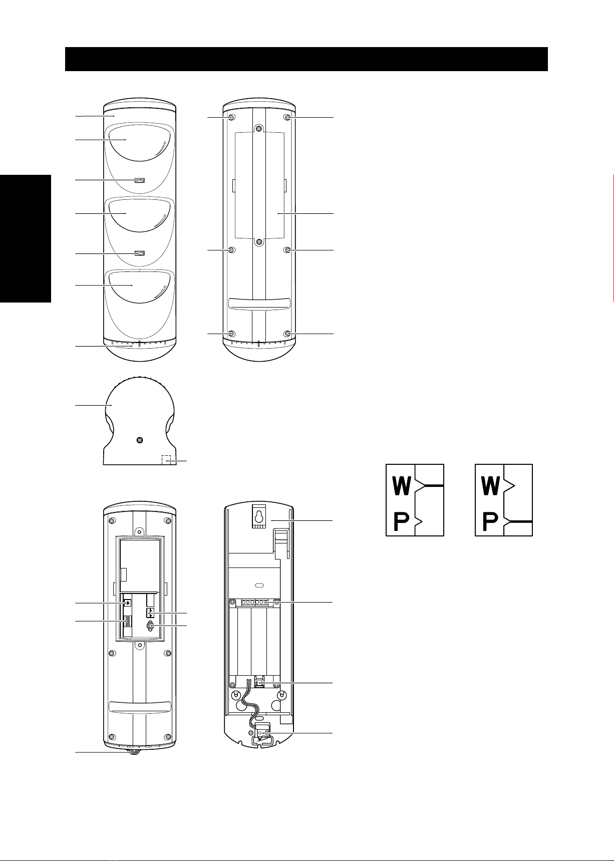
2. NAMES OF PARTS AND THEIR OPERATIONS
aLens 1
This lens is for collecting the heat in the detection
area.
bLens 2
This lens is for collecting the heat in the detection
area.
cLens 1’
This lens is for collecting the heat in the detection
area.
dAlarm LED 1
This LED lights or flashes red to indicate the
operating status of the device.
eAlarm LED 2
This LED lights or flashes red to indicate the
operating status of the device.
fCover
This is the front cover of the device.
gLower cover
This is the bottom cover of the device.
hSmall cover
This is the cover of the setting switches.
iCover screw
These screws are used when removing the cover.
jKnockout
Break this knockout for wiring on the wall.
kSensitivity volume
This adjusts the detection sensitivity.
lDip switch
The dip switches are used to set the various
functions of the device.
mAlarm mode index
This index indicates the alarm mode.
Wide mode Pet Alley mode
nBoard fix screw
This is a screw for fixing the board in place.
oRelay cable
This is a cable for connecting the main device
and mounting base.
pTerminals
These are terminals for the cable connection to
other equipment.
qRelay cable connector
This is a connector for connecting the relay cable
from the main device.
rTamper switch
This is a switch that detects opening and closing
of the lower cover.
sMounting base
This is used when mounting this device on a wall
or other object.
Main device front Main device rear
Main device rear Mounting base
f
a
d
b
e
c
g
i
i
i
i
h
i
i
g
j
k
l
o
m
n
s
q
p
r

3
English
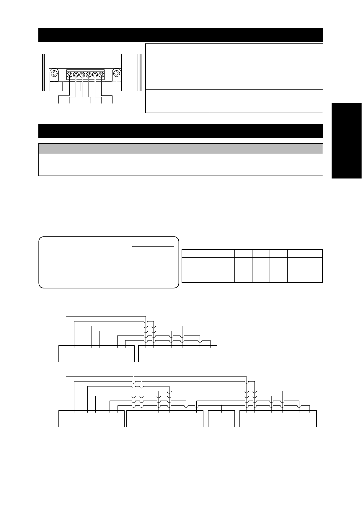
3. NAMES OF TERMINALS AND THEIR OPERATIONS
Terminals of Mounting base
abcdef
E+ E- COM NC TP1
TP2
Terminal symbol/Name Operation
Power supply input
(a:E+, b:E-)
A power supply of 9.0 V to 28.0 V DC is input. It has the
polarity.
Alarm output
(c:COM, d:NC)
This is the 1b non-voltage output.
The allowable contact capacity is 30 V DC/0.3 A
(resistor load).
*When power is not supplied,the output opens.
Tamper output
(e:TP1, f:TP2)
This is the 1b contact component non-voltage output.
The allowable contact capacity is 30 V DC/0.1 A
(resistor load).
*When power is not supplied,the output opens.
4. WIRING MATERIALS AND WIRING METHODS
CAUTION
Do not wire near equipment that is a strong source of noise.
Do not wire in parallel to commercial power supplies or power lines.
Do not use aerial wiring. All of these installation could result in a malfunction.
Power line wiring
For the wiring materials of power input wires, use wires that have a resistance lower than the maximum allowable
resistance found using the formula below.
To simplify the calculation method in this example, the calculation method is described for the condition where the all
detectors are installed farthest from the power supply device (so that the allowable resistance is minimized).
Single wire (mm)
ø
0
.
50
ø
0
.
65
ø
0
.
80
ø
0
.
90
ø
1
.
00
ø
1
.
20
Single wire (AWG)
24 22 20 19 18 16
Twisted wire (mm2)
0
.
20 0
.
40 0
.
50 0
.
75 0
.
90 1
.
30
Resistance (
Ω
/km)
89 56 37 29 24 16
*Use a wire material that ranges from AWG24 to AWG16.
Wire Table
Calculation method for wire length in one
direction from power supply unit to this detector
Vc - Vs
Maximum allowable resistance
value for wire material R [Ω/km] =
1.2 × (2×L) × i
Vc: Output voltage of power supply unit [V]
Vs: Minimum operating voltage of this device = 9 V
L : The wire length from this device to power supply unit (km)
i : Current consumption of this device = 0.025 A
Wire examples
E+ E- 1 C T1 T2
Power supply
output
Sensor input
Error input
E+ E- COM NC TP1 TP2
Power supply
input
Detection
output
Tamper
output
E+ E- 1 C T1 T2
Power supply
output
Sensor input
Error input
Crimping
E+ E- COM NC TP1 TP2
Power supply
input
Detection
output
Tamper
output
E+ E- COM NC TP1 TP2
Power supply
input
Detection
output
Tamper
output
Security receiver Detector 1 Detector 2
Security receiver Detector
aOne channel, single-detector example (1b contact)
bOne channel, two-sensor example (1b contact)
SIR10S wiring examples
4
English
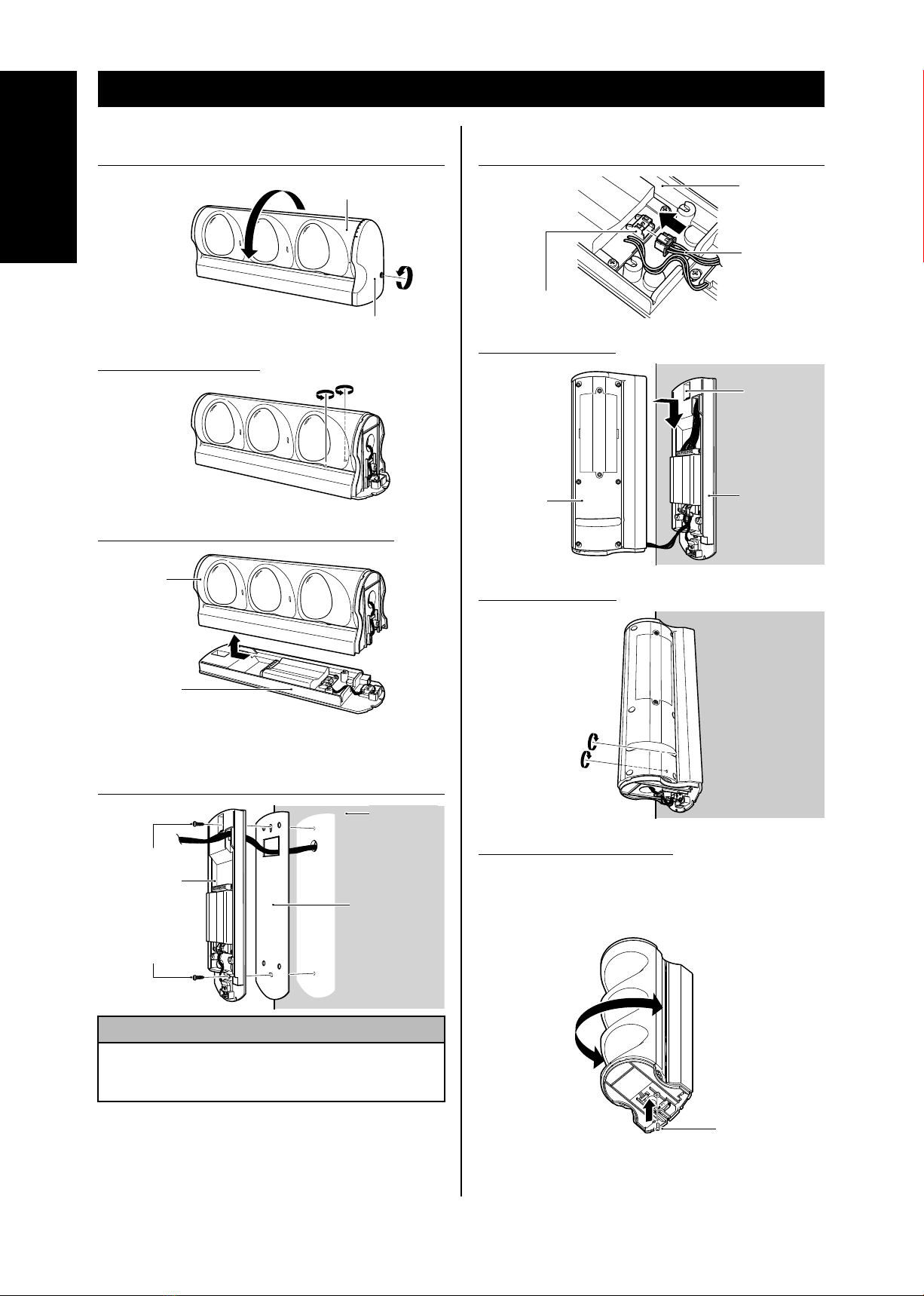
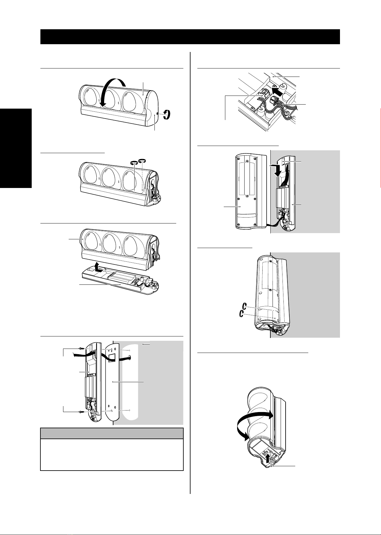
5. INSTALLATION PROCEDURE
1Remove the lower cover, and rotate the main device
by 90 degrees.
Main device
Lower cover
2Loosen the two screws.
3Remove main device from the mounting base.
Main device
Mounting base
4Use the device mounting screws to secure the
mounting base and back sponge to the wall surface
and connect the wiring.
Device mounting
screws
Mounting base
Device mounting
screws
Wall surface
Back sponge
(Back sponge
is affixed to the
mounting base by
an adhesive tape.)
CAUTION
Be sure to install the main device so that it is parallel
to the ground surface or floor. If it is installed at a tilt, a
malfunction or breakdown could result.
5Connect the relay cable of the main device to the
connector of the mounting base.
Relay cable connector
Mounting base
Relay cable
6Fit the main device.
Main device Mounting base
Hang the
hook of the
main device
rear side.
7Tighten the screws.
8About how to use lock screw.
* A locking mechanism of the rotary prevention
becomes stronger by using an attached lock
screw when the detection area of the detector was
decided.
Lock screw M3 × 8
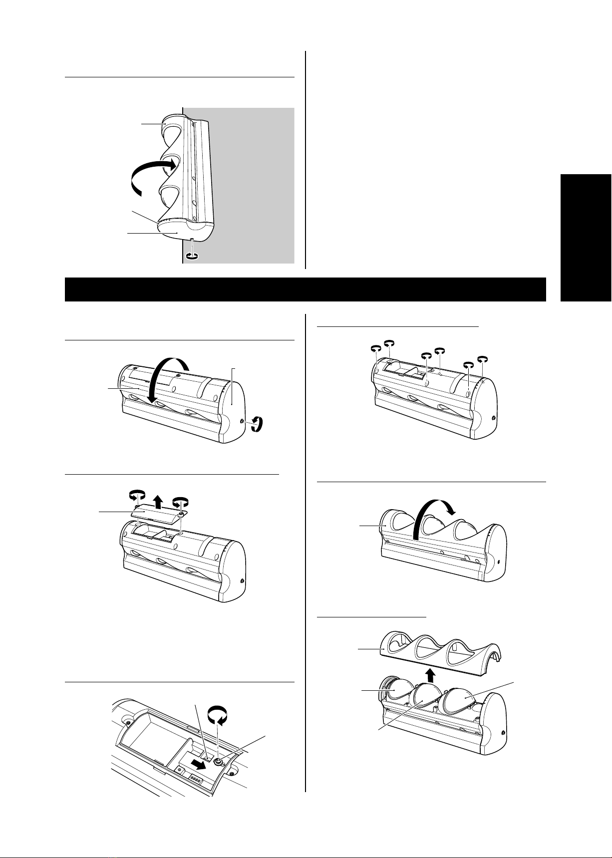
5
English
9Align the alarm direction, and tighten the screw of the
lower cover.
* Check the alarm direction index to make sure the
direction.
Main device
Lower cover
Alarm direction
index
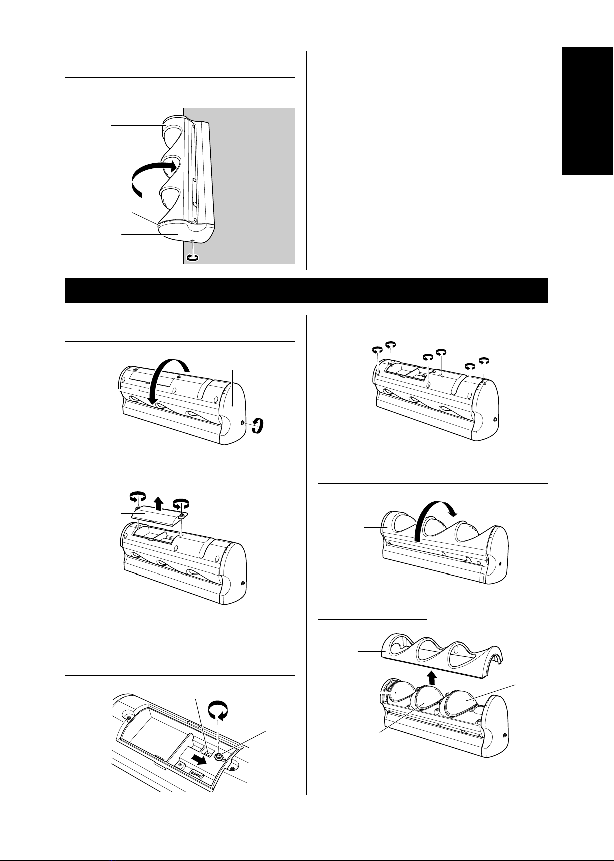
6. USING AS A PET ALLEY MODE (The device is set to the wide mode in default)
1Loosen the lower cover screw by about 5 mm, and
rotate the main device by 180 degrees.
Main device
Lower cover
2Loosen the two screws, and take off the small cover.
Small cover
3Loosen the board fix screw, and slide all the way
in the direction of the arrow. Check that the alarm
selection index is in the "P" position, and tighten the
board fix screw.
Alarm selection index
Board fix screw
4Loosen the six cover screws.
5Rotate the main device by 180 degrees so that it is
facing forward.
Main device
6Remove the front cover.
Cover
Lens 1
Lens 2
Lens 1’
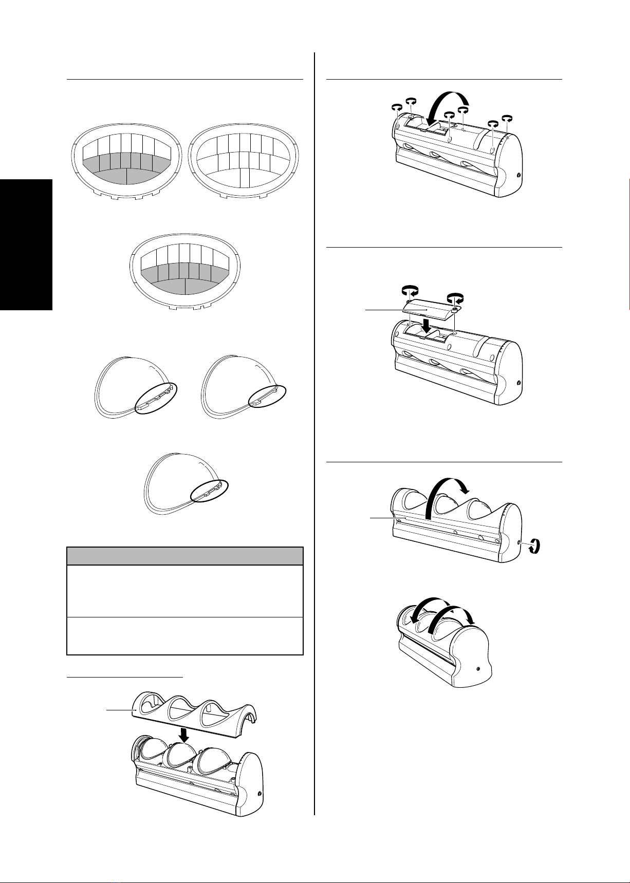
6
English
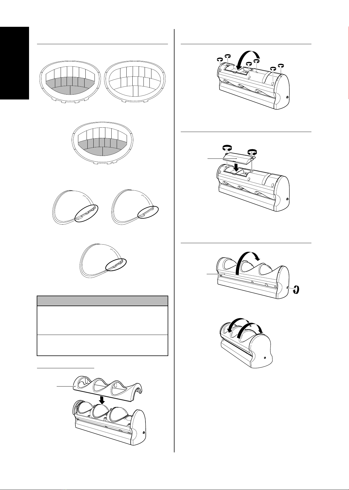
7Remove Lens 1, 1’ and affix masking tape to the
inside of Lens 1, 1’.
The masking locations are "H" to "P" on Lens 1, 1’.
Lens 1 configuration Lens 2 configuration
ABCDEFG
HIJKLMN
OP
abcdefg
n
m
l
k
j
i
h
o
Lens 1’ configuration
ABCDEFG
HIJKLMN
OP
Lens 1 Lens 2
Lens 1’
CAUTION
The shape of the projections on lens 1, 1’ and lens 2
are different. When mounting the lens, be careful not
to mistake them. This could cause a malfunction or
breakdown.
After the lens is removed, do not touch the main
device internal parts. This could cause a malfunction or
breakdown.
8Mount the front cover.
Cover
9Rotate the main device by 180 degrees, and tighten
the six cover screws.
10 Set back the small cover, and tighten the two screws.
* The small cover can be mounted in either direction.
Small cover
11 Rotate the main device, align the alarm direction,
and then tighten the lower cover screws to secure in
place.
Main device
Rotation is possible 180
degrees in the left
direction. Rotation is possible
135 degrees in the
right direction.
7
English
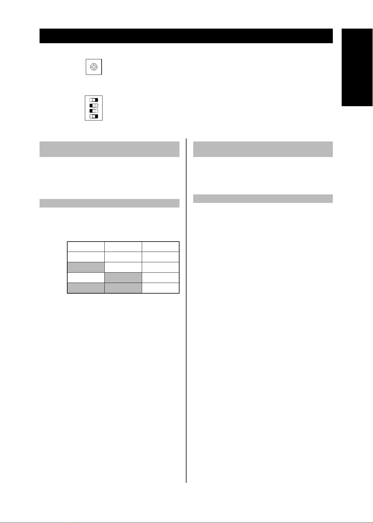
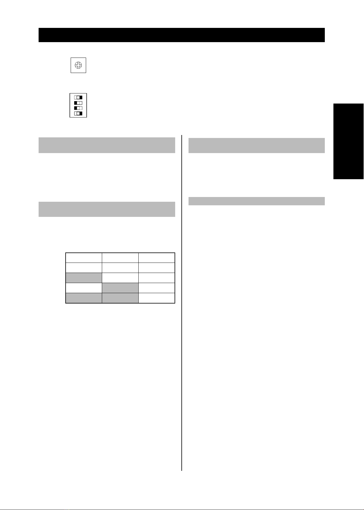
7. SETTING SWITCHES
Make the switch settings after removing the small cover from the main device.
Setting volume 1..................Sensitivity
Setting switches 1 and 2......Pulse count (Default: OFF, ON)
Setting switch 3 ...................LED indicator (Default: ON)
Setting switch 4 ...................LED precaution (Default: OFF)
1 2 3 4
ON OFF
Vol.1
1. Detection sensitivity selection function
(Sensitivity volume)
The detection sensitivity of the detector can be adjusted.
Range: 50% - 100% - 150%
The default detection sensitivity is 100%.
Operation:
When set to 100%, the detection sensitivity when
walking at 1 m/s in a 35°C environment is 1.5°C.
2. Pulse count function (Setting switches 1 and 2)
Detection operation is performed by a preset number of
signal inputs.
Function selection: Set the setting switches to select one
of the four types below.
(Default
setting)
Switch 1 Switch 2 No. of signals
On On 1
Off On 2
On Off 3
Off Off 4
Operation
:
The number of signal inputs within 10 seconds
are countered, and if they reach to a preset
count, the detection operation is performed.
When 10 seconds elapses from the last signal
input, the count value is reset.
Normally, when a person passes through a zone,
one or two signal inputs are obtained, but if the
temperature difference is small between the
person and the background of the floor or wall,
only one signal is obtained. Therefore, keep this
point in mind when making the setting.
3. LED indicator selection function
(Setting switch 3)
On : Alarm LEDs 1 and 2 (red) are normally off, and turn
on at detection. (Default setting)
Off : Alarm LEDs 1 and 2 (red) are normally off, and do
not turn on at detection.
4. LED precaution (Setting switch 4)
The LED alarm is an indicator that constantly alternates
turning on of alarm LEDs 1 and 2.
On : The LED alarm is used. This function can be used
even though LED indicator selection is off.
Off : The LED alarm is not used. (Default setting)

8
English
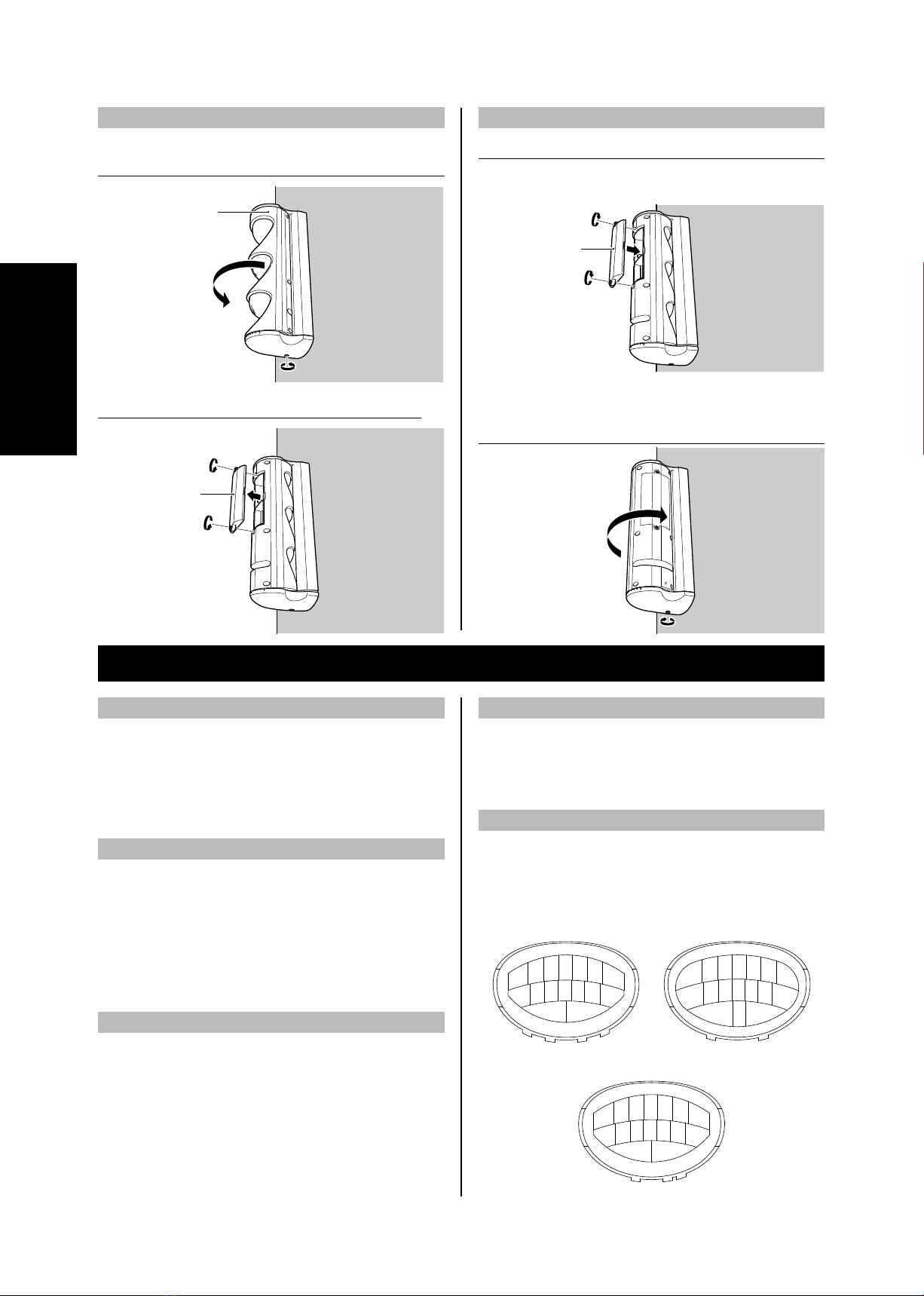
Removing
1Loosen the lower cover screw by about 5 mm, and
rotate the main device by 180 degrees.
Main device
2Loosen the two screws, and take off the small cover.
Small cover
8. AUXILIARY FUNCTIONS
1. Detection system selection function
Wide mode
:
Install at a height from 2 to 3.0 m. In the default
setting, the Wide mode is set.
Pet alley mode: Install at a height from 0.8 to 1.2 m.
This is used when large pets may be falsely
detected by the Wide mode.
2. Warmup function
Function selection: This function is always enabled
regardless of the switch setting.
Operation
:
To stabilize the detection function of the detector,
the detection operation is not performed for
about 50 seconds after the power is on. During
the warmup operation, alarm LEDs 1 and 2 (red)
flash once a second.
3. Self-diagnostic function
This detects errors in the detector itself.
Function selection: This function is always enabled
regardless of the switch setting.
Operation
:
When an error occurs in the element or signal
amplification unit, alarm LEDs 1 and 2 (red) flash
once a second, and continue to send the alarm
output until the power is turned off. In this case,
the device must be replaced.
4. Tamper function
This detects opening and closing of the lower cover.
Function selection: This function is always enabled
regardless of the switch setting.
Operation
:While the lower cover is opened, the tamper
output is sent.
5. Masking function
If causes of false alarm are in the detection area (such
as trees and outdoor air-conditioning units) and causing
malfunctions, mask the lens to disable that detection sector.
Affix the masking tape by referring to the zone diagram
shown in "12. Detection Area".
Lens 1 configuration Lens 2 configuration
Aag
Bb
Cc
Dd
Ee
Ff
G
Hh
Ii
Jj
Kk
Ll
Mm
Nn
OP o
Lens 1’ configuration
ABCDEFG
HIJKLMN
OP
Mounting
1Fit the small cover, and tighten and secure the two
screws.
* The small cover can be mounted with the top and
bottom in either direction.
Small cover
2Rotate the main device, align the alarm direction, and
then tighten the lower cover screws to secure in place.
Mounting and removing the small cover

9
English
9. OPERATION CHECK ~ WALK TEST
(1) The warmup function runs for 50 seconds after the power is turned on, and the detection operation is not performed.
(The alarm LED flashes during this time.)
(2) Once the warmup is completed, walk through the detection area along the potential route of an intruder.
If the alarm LED does not turn on, set the detection area, sensitivity, and pulse count again, and repeat the operation
check.
10.TROUBLESHOOTING
If this detector does not work correctly, be sure to check the supply voltage and polarity. If the detector is still not
working correctly even though power is being supplied properly, find the cause and remedy of the problem by referring
to the table below.
Symptom Cause Remedy
The detector does not work at all.
(The alarm LED (red) does not turn on.)
Sometimes, the detector does not work.
Glass, screen, or other obstacle is blocking
the detection zone.
Move the obstacle, or readjust the
detection area.
The relay cable is not connected. Connect the relay cable.
The intruder does not pass through the
detection zone.
Readjust the detector direction so that the
intruder will pass through the detection
zone.
The detector is activated even though there
is no intruder.
(The alarm LED (red) turns on.)
The detector is near a source of electrical
noise, or the wiring is near a power source
or power line.
Change the installation location.
Change the wiring location.
A sudden change in temperature has
occurred.
Move the heat source or mask the
correspond zone of the lens.
Readjust the detection area.
Sunlight, a car's headlights, or other light
source has entered the background of the
detector or detection area.
Readjust the detection area or mask the
correspond zone of the lens.
Trees, laundry, or other moving objects are
within the detection area.
Remove the moving object from the
detection area or mask the correspond
zone of the lens.
Readjust the detection area.
Change the installation location.
The alarm LED (red) turns on, but the
receiver alarm is not output. The receiver is not in the alarm status. Set the receiver to the alarm status.
The alarm LED (red) flashes (once a
second) continuously.
The self-diagnostic function is activated
due to the detector error. Replace the detector unit.
10
English
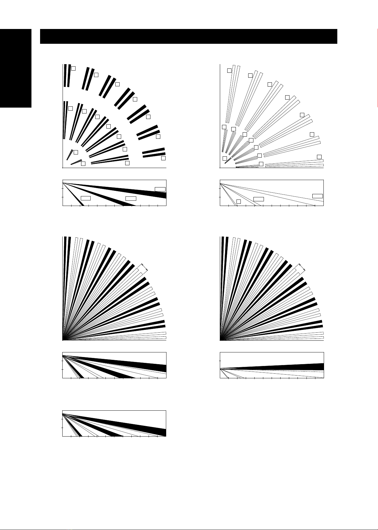
11. DETECTION AREA
Lens 1,1’ zone configuration diagram Lens 2 zone configuration diagram
A
B
C
D
E
F
G
HI
J
K
L
M
N
O
O, P
12 (m)
12 (m)
0
2.5 (m)
1.0 (m)
05 (m) 10 (m) 12 (m)
H~N
A~G
Side View
Top View
P
a
b
c
d
e
f
g
hi
j
k
l
m
n
o
o
12 (m)
12 (m)
0
2.5 (m)
1.0 (m)
05 (m) 10 (m) 12 (m)
h~na~g
Side View
Top View
Wide Alarm Area Diagram Pet Alley Alarm Area Diagram
12 (m)
12 (m)
0
2.5 (m)
1.0 (m)
05 (m) 10 (m) 12 (m)
Side View
Top View
1 (m)
12 (m)
12 (m)
0
2.5 (m)
1.0 (m)
05 (m) 10 (m) 12 (m)
Side View
Top View
1 (m)
When the board is slid to the top (opposite direction from pet alley)
2.5 (m)
1.0 (m)
05 (m) 10 (m) 12 (m)
Side View
(The maximum alarm distance is 9 m.)
Set the detector mounting height to 2.0 m to 3.0 m above the floor or ground for the wide mode and 0.8 m to 1.2 m
above the floor or ground for the pet alley mode.
The detection area can be adjusted ±45° horizontally, and the vertical direction can be adjusted by sliding the board.
The detection zone consists of Lens1,1’and Lens2 zone configurations.
11
English
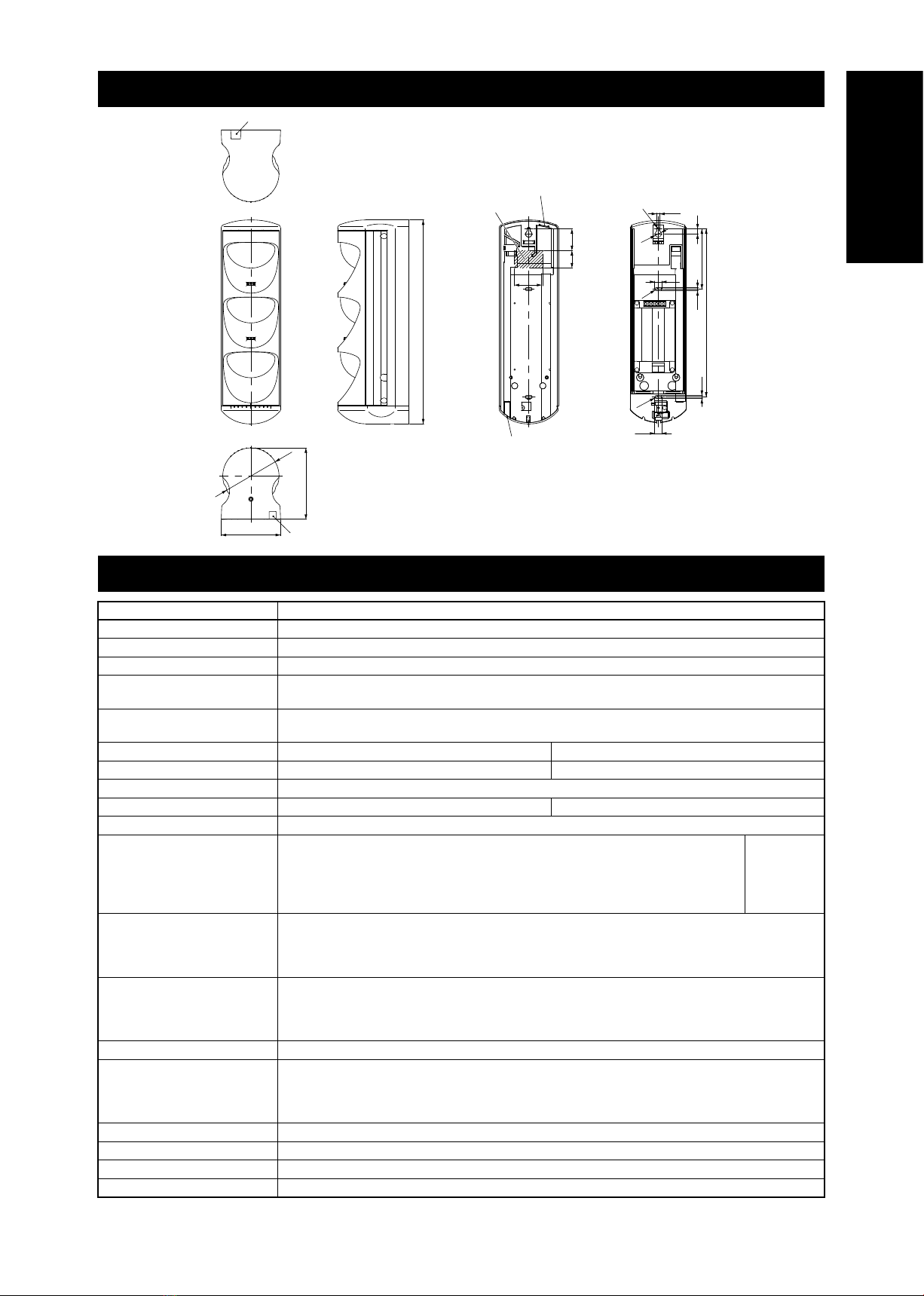
12. DIMENSIONS
Knockout
Knockout
Knockout
Wire hole position
Knockout Mounting base
82.3
99
ø78
282.7
3024
233
83.5 74.5
4.5
9.5
9.5
9.5
4.5
40
40
(R)
(R)
(R)
ø9
13. SPECIFICATIONS
Product name Intelligent outdoor detector
Model SIR10S
Power 9 – 28 V DC
Current draw 25 mA (maximum)
Operating temperature and
humidity range -25 ~ +50°C RH 95% or less
Storage temperature and
humidity range -30 ~ +60°C RH 95% or less
Alarm method Wide mode Pet alley mode
Installation height 2m ~ 3.0m 0.8m ~ 1.2m
Detection area 12m, 84°
Detection zone (sector) 47 pairs(94 sectors) 29 pairs(58 sectors)
Detection method Passive infrared system
Indicator lights
Alarm LED 1=Red, Alarm LED 2=Red
Self-diagnostic function :Alarm LEDs 1, 2 flashing (once a second)
Warmup function :Alarm LEDs 1, 2 flashing (once a second)
At detection :Alarm LEDs 1, 2 fully light
LED precaution :Alarm LEDs 1, 2 turn on alternately
High
Priority
Low
Detection output
Non-voltage contact (1b)
Contact operation :One-shot (3 seconds)
Contact capacity :30 V DC 0.3 A (resistance load)
Output resistance when closed
:3 Ωor less
Tamper output
Non-voltage contact (1b)
Contact operation :When the lower cover is removed or opened
Contact capacity :30 V DC 0.1 A (resistance load)
Output resistance when closed
:3 Ωor less
Detection speed 0.3 ~ 2.0 m/sec
Detection sensitivity
1.5°C (temperature difference with background)
Walk speed :1 m/sec
Environment temperature :+35°C
Sensitivity setting :100%
Main device movable range Horizontal direction ±45°
Installation location indoor/outdoor (IP55)
Weight 800g
Color White DIC G-21

12
14. OPTIONAL COMPONENTS
The optional components shown in the table right are available for this
detector. Purchase them separately if needed.
The specifications of the optional components are subject to
change without notice for improvements
15. MAINTENANCE
Daily inspection
If the detector is dirty, wipe it off using a soft cloth with a small amount of soap solution. Never use thinner or
alcohols.
Perform an operation check on a regular basis about once a week. Also, check operation if storage box/house or
walls/screens to block the detection zones.
Regular inspection
Perform an operation check that includes that system about once a year. Be sure to also check the items below.
Is the supply voltage suitable?
Is the Alarm output working correctly (is the output resistance correct)?
Is the Tamper output working correctly (is the output resistance correct)?
Product number Product name
PMK1 Pole mount kit
AE1171
4-2-2 Shin-Miyakoda,kitaku,Hamamatsu,Shizuoka 431 2103 Japan
Phone:(81)53-428-4116 Fax:(81)53-428-4119
The specifications and design are subject to change without notice for incorporating improvements.
Atsumi guarantees the quality of our products for a period of one year based on provisions of the warranty. If any
defects should occur in this product, please contact the dealer where you made the purchase.

1
Español
4-2-2 Shin-Miyakoda,kitaku,Hamamatsu,Shizuoka 431 2103 Japan
Phone:(81)53-428-4116 Fax:(81)53-428-4119
Gracias por utilizar el Sistema de alarma de intrusión
de Atsumi:
Detector inteligente para exteriores. Lea
detenidamente este manual de instalación antes de la
instalación para garantizar que ésta se realice correctamente.
Le recomendamos que guarde este manual en un lugar
seguro para consultarlo cuando sea necesario.
<Exención de responsabilidad>
Este detector es un dispositivo para la detección de intrusiones
ilegales, no para la prevención de robos. El cliente debe utilizar
este producto como parte de un sistema de seguridad integral.
Atsumi no se responsabiliza por los daños que surjan debido
a robos u otras causas.
Sistema de alarma de intrusión
Sistema automático de control
Detector inteligente para exteriores
SIR10S
Tri Watcher®
Manual de instalación
1. COMPONENTES DEL PRODUCTO
Los componentes del producto se muestran en la tabla a continuación. Compruebe que se hayan incluido todos los
componentes antes de comenzar la instalación.
Componente Cantidad
Dispositivo principal 1
Tornillos de instalación del dispositivo principal (diámetro nominal 4 x 30) 2
Cinta adhesiva para la lente 1 2
Tornillo de bloqueo (diámetro nominal M3x8) 1
Manual de instalación (este manual) 1
Cinta adhesiva para la lente 2 1
2
Español
aLente 1
Esta lente sirve para absorber el calor en el área
de detección.
bLente 2
Esta lente sirve para absorber el calor en el área
de detección.
cLente 1’
Esta lente sirve para absorber el calor en el área
de detección.
dLED 1 de la alarma
Este LED se ilumina o parpadea en rojo para
indicar el estado operativo del dispositivo.
eLED 2 de la alarma
Este LED se ilumina o parpadea en rojo para
indicar el estado operativo del dispositivo.
fCubierta
Es la cubierta frontal del dispositivo.
gCubierta inferior
Es la cubierta inferior del dispositivo.
hCubierta pequeña
Ésta es la tapa de los interruptores de configuración.
iTornillos de la cubierta
Estos tornillos se utilizan para quitar la cubierta.
jTroquelado
Rompa esta tapa prepunzonada para el cableado
de la pared.
kVolumen de sensibilidad
Esto ajusta la sensibilidad de detección.
lInterruptor DIP
Los interruptores DIP se usan para configurar las
diferentes funciones del dispositivo.
mÍndice del modo de alarma
Este índice indica el modo de alarma.
Modo ancho
Modo de pasillo con mascotas
nTornillo de fijación del tablero
Este tornillo sirve para ajustar la placa en su
lugar.
oCable del relé
Este cable conecta el dispositivo principal con la
base de montaje.
pTerminales
Éstos son terminales para la conexión de cables
a otros equipos.
qConector del cable del relé
Sirve para conectar el cable del relé del
dispositivo principal.
rInterruptor de seguridad
Este interruptor detecta la apertura y cierre de la
cubierta inferior.
sBase de montaje
Se utiliza cuando el dispositivo se instala en una
pared u otro objeto.
2. NOMBRES DE LAS PIEZAS Y SU FUNCIONAMIENTO
Parte frontal del
dispositivo principal Parte trasera del
dispositivo principal
Parte trasera del
dispositivo principal Base de montaje
f
a
d
b
e
c
g
i
i
i
i
h
i
i
g
j
k
l
o
m
n
s
q
p
r
3
Español
3. NOMBRES DE LOS TERMINALES Y SU FUNCIONAMIENTO
Terminales de la base de instalación
abcdef
E+ E- COM NC TP1
TP2
Símbolo y nombre del terminal
Funcionamiento
Entrada de la fuente de
alimentación (a:E+, b:E-)
Fuente de alimentación de 9 a 28 V CC de entrada.
No tiene la polaridad.
Salida de alarma
(c:COM, d:NC)
Ésta es la salida 1b sin tensión.
La capacidad de contacto permitida es de 30 V CC/0,3 A
(carga de la resistencia).
*Cuando no se suministra alimentación, se abre el caudal.
Salida de seguridad
(e:TP1, f:TP2)
Ésta es la salida 1b sin tensión del componente de contacto.
La capacidad de contacto permitida es de 30 V CC/0,1 A
(carga de la resistencia).
*Cuando no se suministra alimentación, se abre el caudal.
4. MATERIALES Y MÉTODOS DE CABLEADO
PRECAUCIÓN
No realice el cableado cerca de equipos que sean una fuente de ruidos fuertes.
No realice el cableado en paralelo a las fuentes de alimentación comerciales o líneas de alta tensión.
No utilice cableado aéreo. Todas estas instalaciones pueden resultar en un funcionamiento incorrecto.
Cableado de la línea de alta tensión
Para los materiales de cableado de los cables de entrada de energía, utilice cables que tengan una resistencia
menor que el máximo permitido, que se encuentra en la fórmula a continuación.
Para simplificar el método de cálculo en este ejemplo, éste se describe para la condición donde todos los detectores
están instalados en un lugar que está más alejado del dispositivo de fuente de alimentación (para que se minimice la
resistencia permitida).
Cable unifilar (mm)
ø
0
,
50
ø
0
,
65
ø
0
,
80
ø
0
,
90
ø
1
,
00
ø
1
,
20
Cable unifilar (AWG)
24 22 20 19 18 16
Cable trenzado (mm
2
)
0
,
20 0
,
40 0
,
50 0
,
75 0
,
90 1
,
30
Resistencia (/km)
89 56 37 29 24 16
*Utilice un material de cableado entre AWG24 y AWG16.
Tabla de cables
Método de cálculo para la distancia del cable en una dirección
de la unidad de fuente de alimentación a este detector
Vc - Vs
Valor máximo permitido de resistencia
para materiales de cableado R [
/km]
=
1,2 x (2 x L) x i
Vc: Tensión de salida de la unidad de fuente de alimentación [V]
Vs:
Tensión mínima de funcionamiento de este dispositivo = 9 V
L : Longitud del cable desde este dispositivo hasta la unidad
de alimentación (km)
i : Consumo actual de este dispositivo = 0,025 A
Ejemplos de cable
E+ E- 1 C T1 T2
Salida de la fuente
de alimentación
Entrada del
sensor
Error de
entrada
E+ E- COM NC TP1 TP2
Entrada de la fuente
de alimentación
Salida de
detección
Salida de
seguridad
E+ E- 1 C T1 T2
Salida de la fuente
de alimentación
Entrada del
sensor
Error de
entrada
Ondulación
E+ E- COM NC TP1 TP2
Entrada de la fuente
de alimentación
Salida de
detección
Salida de
seguridad
E+ E- COM NC TP1 TP2
Entrada de la fuente
de alimentación
Salida de
detección
Salida de
seguridad
Receptor de seguridad Detector 1 Detector 2
Receptor de seguridad Detector
aEjemplo de un canal, detector único (contacto 1b)
bEjemplo de un canal, dos sensores (contacto 1b)
Ejemplos de cableado SIR10
4
Español
5. PROCEDIMIENTO DE INSTALACIÓN
1Quite la cubierta inferior y gire el dispositivo principal
90 grados.
Dispositivo principal
Cubierta inferior
2Afloje los dos tornillos.
3Quite el dispositivo principal de la base de montaje.
Dispositivo
principal
Base de montaje
4Use los tornillos de instalación del dispositivo para
asegurar la base de instalación y la esponja soporte a
la superficie de la pared y, a continuación, conecte el
cableado.
Base de montaje
Tornillos de montaje
del dispositivo
Superficie de
la pared
Esponja soporte
(La esponja
soporte está
fijada a la base
de instalación con
cinta adhesiva.)
Tornillos de montaje
del dispositivo
PRECAUCIÓN
Asegúrese de instalar el dispositivo principal de modo
que quede paralelo a la superficie del suelo o el piso. Si
está instalado en una inclinación, podría ocasionar un
funcionamiento incorrecto o un desperfecto.
5Conecte el cable del relé del dispositivo principal al
conector de la base de montaje.
Conector del
cable del relé
Base de montaje
Cable del relé
6Ajuste el dispositivo principal.
Dispositivo
principal Base de montaje
Cuelgue el
gancho en la
parte posterior
del dispositivo
principal
7Ajuste los tornillos.
8Sobre cómo utilizar el tornillo de bloqueo.
* El mecanismo de bloqueo de prevención de
rotación será más fuerte si se usa el tornillo de
bloqueo adjunto al decidir el área de detección del
detector.
Tornillo de bloqueo
M3 × 8
5
Español
9Alinee la dirección de la alarma y apriete el tornillo de
la tapa inferior.
* Compruebe el índice de dirección de la alarma,
para asegurarse de la dirección.
Dispositivo principal
Cubierta inferior
Graduador de
selección de la alarma
6. USO EN MODO DE PASILLO CON MASCOTAS (El dispositivo está configurado por defecto en el modo ancho.)
1Afloje el tornillo de la cubierta inferior unos 5 mm y
gire 180 grados.
Dispositivo
principal
Cubierta inferior
2Afloje los dos tornillos y quite la cubierta pequeña.
Cubierta
pequeña
3
Afloje el tornillo de fijación del tablero, y deslícelo
completamente en la dirección de la flecha. Compruebe
que el índice de selección de la alarma esté en la
posición "P" y, a continuación, apriete el tornillo de
fijación del tablero.
Graduador de selección
de la alarma
Tornillo de fijación
del tablero
4Afloje los seis tornillos de la cubierta.
5Gire el dispositivo principal 180 grados de modo que
quede hacia adelante.
Dispositivo
principal
6Quite la cubierta frontal.
Cubierta
Lente 1
Lente 2
Lente 1’
6
Español
7Quite la lente 1, 1’ y fije cinta adhesiva al interior de la
lente 1, 1’.
Donde debe colocar la cinta adhesiva está marcado
como "H" o "P" en la lente 1, 1’.
Configuración de la lente 1 Configuración de la lente 2
ABCDEFG
HIJKLMN
OP
abcdefg
n
m
l
k
j
i
h
o
Configuración de la lente 1’
ABCDEFG
HIJKLMN
OP
Lente 1 Lente 2
Lente 1’
PRECAUCIÓN
Las formas de proyección de las lentes 1, 1’ y 2 son
diferentes. Cuando monte las lentes, tenga cuidado de
no confundirlas. Esto podría provocar un funcionamiento
incorrecto o desperfecto.
Una vez que quitó la lente, no toque las piezas internas
del dispositivo principal. Esto podría provocar un
funcionamiento incorrecto o desperfecto.
8Monte la cubierta frontal.
Cubierta
9Gire el dispositivo principal 180 grados, y apriete los
seis tornillos de la tapa.
10 Vuelva a colocar la tapa pequeña y apriete los dos
tornillos.
* La tapa pequeña puede montarse en cualquier
dirección.
Cubierta
pequeña
11 Gire el dispositivo principal, alinee la dirección de la
alarma y después ajuste los tornillos de la cubierta
inferior para sujetarlo en su lugar.
Dispositivo
principal
Se puede rotar
180 grados hacia
la izquierda. Se puede rotar
135 grados hacia
la derecha.
7
Español
7. INTERRUPTORES DE AJUSTE
Realice el ajuste de los interruptores después de quitar la cubierta pequeña del dispositivo principal.
Ajuste de volumen 1…………… Sensibilidad
Interruptores de ajuste 1 y 2......Recuento de pulsos (Predeterminado: OFF, ON)
Interruptor de ajuste 3 ...............Indicador LED (Predeterminado: ON)
Interruptor de ajuste 4 ...............LED de precaución (Predeterminado: OFF)
1 2 3 4
ON OFF
Vol.1
1. Función de selección de sensibilidad de
detección (Volumen de sensibilidad)
Se puede ajustar la sensibilidad de detección del
detector.
Rango: 50% - 100% - 150%
La sensibilidad de detección predeterminada es del 100%.
Funcionamiento
:Cuando está ajustado en 100%, la
sensibilidad de detección cuando se camina
a 1 m/s en un ambiente de 35 °C es de 1,5 °C.
2. Función de recuento de pulsación
(Interruptores de configuración 1 y 2)
La operación de detección se realiza por medio de un
número de entradas de señales preestablecidas.
Selección de la función:Configure los interruptores de ajuste
para seleccionar una de las cuatro funciones
siguientes.
(Configuración
predeterminada)
Interruptor 1 Interruptor 2 N.º de señales
On On 1
Off On 2
On Off 3
Off Off 4
Funcionamiento: Se cuenta el número de entradas de señal
en 10 segundos y, si alcanzan un recuento
preconfigurado, se realiza la operación de
detección. Cuando pasan 10 segundos de la última
señal de entrada, el valor del recuento se reinicia.
Normalmente, cuando una persona pasa por
una zona, se obtienen una o dos entradas de
señal, pero si la diferencia de temperatura entre
la persona y el fondo, ya sea una pared o el
suelo, es pequeña, solamente se obtiene una
señal. Por tanto, tenga este punto en cuenta
cuando realice la configuración.
3. Función de selección del LED indicador
(Interruptor de ajuste 3)
On : Los LED 1 y 2 de la alarma (rojos) suelen estar
apagados y se encienden cuando detectan algo.
(Configuración predeterminada)
Off :
Los LED 1 y 2 de la alarma (rojos) suelen estar
apagados y no se encienden cuando detectan algo.
4. LED de precaución (Interruptor de ajuste 4)
La alarma LED es un indicador que constantemente
alterna el encendido de los LED 1 y 2 de la alarma.
On :
La alarma LED está en uso. Esta función puede utilizarse
incluso cuando el indicador LED está apagado.
Off : La alarma LED no está en uso. (Configuración
predeterminada)
8
Español
Remoción
1Afloje el tornillo de la cubierta inferior unos 5 mm y
gire 180 grados.
Dispositivo principal
2Afloje los dos tornillos y quite la cubierta pequeña.
Cubierta pequeña
8. FUNCIONES AUXILIARES
1.
Función de selección del sistema de detección
Modo ancho : instálelo a una altura de 2 a 3,0 m. En el
ajuste por defecto está configurado el modo ancho.
Modo de pasillo con mascotas : instálelo a una altura de
0,08 a 1,2 m. Se usa cuando el modo ancho puede
detectar incorrectamente mascotas grandes.
2. Función de calentamiento
Selección de la función
:Esta función siempre está activada
sin importar la configuración del interruptor.
Funcionamiento:
Para estabilizar la función de detección
del detector, no se realiza dicha función durante
aproximadam
ente 50 segundos después de
encendida la alimentación. Durante el calentamiento,
los LED 1 y 2 de la alarma (rojos) parpadean una
vez por segundo.
3. Función de autodiagnóstico
Esta función encuentra errores en eldetector mismo.
Selección de la función
:Esta función siempre está activada
sin importar la configuración del interruptor.
Funcionamiento: Cuando se producen errores en el elemento
o la unidad de amplificación de señal, los LED de alarma
1 y 2 (rojo) parpadean una vez durante un segundo, y
siguen enviando la señal de alarma hasta que se apague
la alimentación. En este caso, el dispositivo debe
ubicarse en otro lugar.
4. Función de seguridad
Esta función detecta la apertura y cierre de la cubierta inferior.
Selección de la función
: Esta función siempre está activada
sin importar la configuración del interruptor.
Funcionamiento
: Mientras que la cubierta inferior se abre, se
envía una señal de salida de seguridad.
5. Función de enmascaramiento
Si hay objetos en el área de detección (como árboles o
unidades de aire acondicionado en el exterior) que puedan
provocar falsas alarmas y un funcionamiento incorrecto,
cubra la lente para desactivar ese sensor de detección.
Coloque cinta adhesiva según el diagrama de la zona
que se observa en "1.2 Área de detección".
Configuración de la lente 1 Configuración de la lente 2
Aag
Bb
Cc
Dd
Ee
Ff
G
Hh
Ii
Jj
Kk
Ll
Mm
Nn
OP o
Configuración de la lente 1’
ABCDEFG
HIJKLMN
OP
Montaje
1
Ajuste la cubierta pequeña, ajuste y asegure los dos tornillos.
* La cubierta pequeña puede montarse con la parte
superior e inferior en cualquier dirección.
Cubierta pequeña
2Gire el dispositivo principal, alinee la dirección de la
alarma y después ajuste los tornillos de la cubierta
inferior para sujetarlo en su lugar.
Montaje y remoción de la cubierta pequeña
Table of contents
Languages:
Popular Security System manuals by other brands

Visonic
Visonic MINI-ALERT installation instructions

Denver
Denver SHA-150 Quick user guide

Alderon Industries
Alderon Industries WaterPro WaterSpotter AVFD Series Operation, maintenance and installation manual

Honeywell
Honeywell Ademco VISTA-50P Programming guide

eao
eao 56 Series Assembly instructions

Lorex
Lorex L15LD400 series instruction manual


