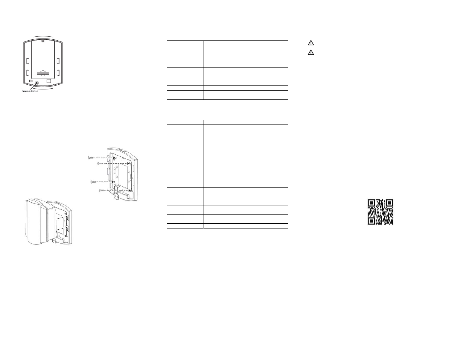
manuals.online logo
Brands
  1. Home
  2. •
  3. Brands
  4. •
  5. Rondish
  6. •
  7. Security System
  8. •
  9. Rondish Nexus ILB-21 User manual

Rondish Nexus ILB-21 User manual

This manual suits for next models

1

Other Rondish Security System manuals

Rondish Nexus WCP-11 User manual

Rondish

Rondish Nexus WCP-11 User manual

Rondish Nexus User manual

Rondish

Rondish Nexus User manual

Popular Security System manuals by other brands

Inner Range Concept 2000 user manual

Inner Range

Inner Range Concept 2000 user manual

Climax Mobile Lite R32 Installer's guide

Climax

Climax Mobile Lite R32 Installer's guide

FBII XL-31 Series installation instructions

FBII

FBII XL-31 Series installation instructions

Johnson Controls PENN Connected PC10 Install and Commissioning Guide

Johnson Controls

Johnson Controls PENN Connected PC10 Install and Commissioning Guide

Aeotec Siren Gen5 quick start guide

Aeotec

Aeotec Siren Gen5 quick start guide

IDEAL Accenta Engineering information

IDEAL

IDEAL Accenta Engineering information

Swann SW-P-MC2 Specifications

Swann

Swann SW-P-MC2 Specifications

Ecolink Siren+Chime user manual

Ecolink

Ecolink Siren+Chime user manual

Digital Monitoring Products XR150 user guide

Digital Monitoring Products

Digital Monitoring Products XR150 user guide

EDM Solution 6+6 Wireless-AE installation manual

EDM

EDM Solution 6+6 Wireless-AE installation manual

Siren LED GSM operating manual

Siren

Siren LED GSM operating manual

Detection Systems 7090i Installation and programming manual

Detection Systems

Detection Systems 7090i Installation and programming manual

Se-Kure Controls MicroMini SK-4841 instructions

Se-Kure Controls

Se-Kure Controls MicroMini SK-4841 instructions

Siemens FDM273 manual

Siemens

Siemens FDM273 manual

DSC PC 4010 Programming manual

DSC

DSC PC 4010 Programming manual

UniPOS 6202L quick start guide

UniPOS

UniPOS 6202L quick start guide

AJAX DoubleButton user manual

AJAX

AJAX DoubleButton user manual

Pego ECP APE03 Use and maintenance manual

Pego

Pego ECP APE03 Use and maintenance manual

manuals.online logo
manuals.online logoBrands
  • About & Mission
  • Contact us
  • Privacy Policy
  • Terms and Conditions

Copyright 2025 Manuals.Online. All Rights Reserved.












WirelessBathroomAlarm
ILB‐21&WCP‐11
Revised on 28/04/2021


Manufactured by RondishCompanyLimited
Unit G&H, 4/F, Block 1, Kwai Tak Ind. Ctr.,
15-33 Kwai Tak Street, Kwai Chung, N.T.
Hong Kong
ProductIntroduction

Your Wireless Bathroom Alarm includes everything you need for an emergency
bathroom alarm. The product can be set up as a stand-alone solution, or you
can configure signals to be received by central monitoring equipment in a
larger building management system.
The indication light can be battery operated, or a power lead is included to
allow connection with a central power supply.
The call/reset point included with your purchase is waterproof to IP65 and is
suitable for use in a shower area. If separate call & reset buttons are required
these are available from Rondish upon request. Additional call points or sensor
devices can be paired with the indication light, up to a maximum of 15.
Potential applications include hospitals, schools, elderly homes, hotels,
government offices, and anywhere else an alarm is required to be installed in
toilet or shower areas.
This product was designed to conform with BS 8300-2:2018
























Operation

Bathroom
To raise an alarm – press the CALL button on the WCP-11. A reassurance LED
on the button will stay on while transmitting.
To reset an alarm – press the RESET button on the WCP-11. The ILB-21 can
also be done by touching a magnet to the blue dot on the front of the light, or
pressing the PROGRAM button on the back.
Advanced
Pause – if a bed monitor unit with a pause button has been paired with the ILB-
21, alarms from passive sensors can be disabled to allow a caregiver to attend a
patient without triggering any alarms. This will prevent any bed sensorpads,
floor mat sensors, motion sensors or door sensors from alarming while a
caregiver moves about a patient room. Call buttons will continue to function.

SystemSetup

Step1:Powerthelight – Insert 6 x
C-type alkaline batteries into the
ILB-21. A lead is also provided to
connect with a 12V power source if
the alarm will be frequently used.



Step2:Selectsettings – Remove
front lens using a 2mm flat-head
screwdriver and select light
settings. The dip switches control
whether the ILB-21 will forward
alarms to a central monitor unit or
as a night light. The buzzer volume
is adjustable from 89-108dB.
Switch 1 – far left: Call Forward (On/Off)
 Controls whether alarms from paired devices are forwarded to
Nexus
 Includes WCP-03, WCP-11, TXP-11 and DMS-02
Switch 2 – left center: Signal Bump (On/Off)
 Controls whether signals unpaired devices are forwarded to Nexus
 Includes TXP-11 and bed monitors
Switch 3 – right center: Group Reset (On/Off)
 When set to On position, a reset button will clear alarms from any
device paired with the ILB-21.
Switch 4 – far right: Alternating Lights (On/Off)
 Controls whether lights alternate when in alarm state

Step3:Enterpairing– Press the
Program button on the back of the
indication light. The red and white
sections will both stay ON to indicate
the light is ready for pairing.




Step4:Read‐inwirelessdevices – Trigger an alarm from the sensor you
want to add into memory. If the device code is accepted into memory the ILB-
21 will beep three times and flash either the red or white section. The WCP-11
call/reset button provided will flash the white LED to confirm they are paired;
other wireless devices will flash the red LED to confirm.
The ILB-21 has a memory capacity for 15 devices. In the event the light
memory is already full, an attempt to read in another device will result in a long
beep to indicate is has not been accepted.



Step5:Securemountingplate –
Screw the plastic mounting plate to
the wall where you will want to locate
the indication light. Make sure the
plate is secured before mounting the
light.
Step6:Mountthelight – Snap the
indication light onto the mounting
plate. You will hear a “click” when
the light is securely in place.





OtherFunctions

Clear memory – while already in programming mode hold the Program button
~10s. The red and white LEDs will both flash several times, then turn OFF.
Note that this will remove all paired devices from the memory, so you will need
to re-pair any devices that will continue to be used.
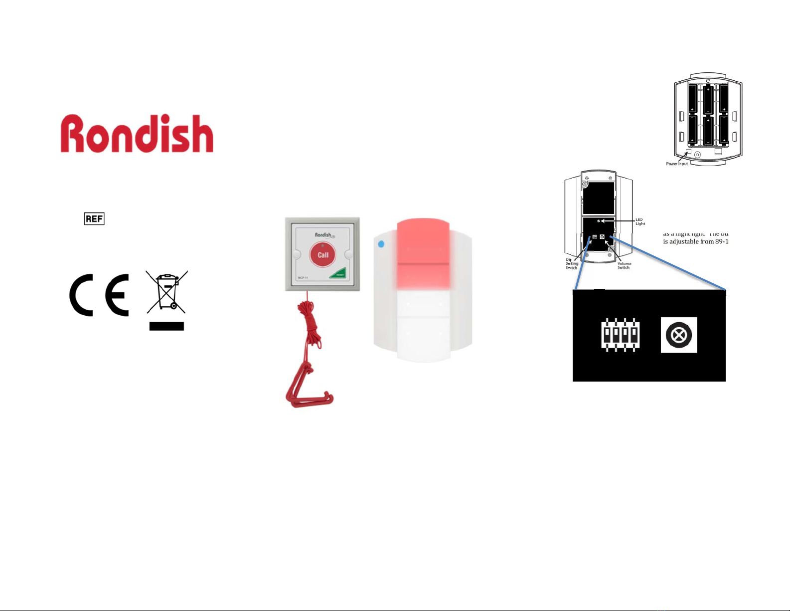
Low battery – The ILB-21 has a red LED indication inside the white section of
the light, which will blink and beep when low battery is detected. The
assurance LED on the WCP-11 will blink once every 5s when low battery is
detected.
ProductSpecifications

Light Indications General alarm LED – Red (top) segment
Bath alarm LED – White (bottom) segment
Low bat LED – Flashes yellow every 10s to
indicate normal status
Red to indicate light low battery, Yellow to
indicate low battery on paired device
Volume 89 – 108dB
Operating Radio
Fre
q
uenc
y
Transmitter: 435MHz
Receiver: 433MHz
Power input 12VDC, 800mA
Batteries 6 x C-t
yp
e alkaline
Dimensions 16 x 11 x 6cm
Weight 680g (with batteries)
CompatibleDevices

OrderReference DeviceDescription
WCP-11
Waterproof call/reset point with pull cord. This
will trigger a bath alarm on the light, and can
reset an alarm from any additional devices that
have triggered the ILB-21. One has been
included with your purchase.
WCP-03, WRE-03 Call & Reset buttons are available as separate
units if necessary.
TXP-11

Panic button with lanyard and man-down alert.
This will activate a general alarm on the light. In
this configuration it is recommended to have a
reset button or monitor paired with the light and
activate Group Reset.
DMS-02

Door strip sensor. This will activate a general
alarm on the light
TM-11(V3) Cordless bed sensorpads can be paired to the
ILB-21 by pressing and releasing. In this
configuration you will need a reset button paired
with the light and activate Group Reset
DON-30 An indication light can forward an alarm signal
to a Nexus terminal with DON-30 connected to i
t
NGM-21 CordFree wireless monitor. This can reset an
alarm on the ILB-21 if it has been paired
AC-04 12V, 800mA power adapter
Warnings

Test regularly to ensure alarms are working properly.

This product uses radio frequency signals, which can be affected by
building layout and construction materials. The manufacturer cannot
guarantee the wireless range you get will match the estimates provided.
You should test that there are no “dead areas” in your facility where
alarms cannot be received.
FAQ/Support
Q. How far away can a call button or sensor be from the Indication Light and
still receive the alarm?
A. Wireless devices will typically have 15~25m indoor range, depending on
the shape and construction of the building. The actual range will vary, so
always test that a call point will trigger the indication light before using the
system.
Q. How long will the batteries last?
A. This will vary greatly depending on the product usage. If infrequently
used as only an emergency alarm, the light has enough battery power to
last one year. When used as an indication light for a frequently used call
system, batteries are projected to give ~6 months of operation. It is
recommended to use a power supply for this type of application, with
batteries as back up in case of power loss.

Q. What devices can I pair with the indication light?
A. A list of products with ordering codes is shown in the Compatible Devices
section of this instruction manual.

For additional product information, scan the QR code below. Rondish will post
information to our website to help address Frequently Asked Questions and
technical support.
