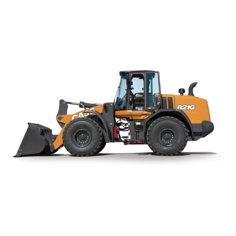
ATTACK 810 Series User manual

Page 1/57
810,820 Series wheel loader operation manual
Updated 8/27/2013
Wheel loader
JST
Series
810,820 Series Wheel Loader
Operation Manual

Page 2/57
810,820 Series wheel loader operation manual
Updated 8/27/2013
Wheel loader
JST
Series
0B
FOREWORD
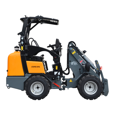
810,820 Series loader is one of ATTACK self-developed new less t an 1ton multi-function mini-
loaders, t is loader is a ideal product for material loading and unloading, s ort-distance transport,
can be matc ed wit many tools, can be realized more kinds of uses, suc as lifting, pulling,
clamp old, digging drill, ground, weeding, feeding fodder, etc. It can widely used in farm, ranc ,
infrastructure, road construction, stations, boatyard and ot er work places, t is mac ine as t e
c aracteristics of t e best economy, safety, and driving comfort. And t ese good c aracteristics
depend on you, loaders and ot er operators to maintain, fully play during operating.
T is manual covers all important knowledge of t e starting use of t e new loader, driving and
operation, care and maintenance for 810,820 series w eel loaders. Please follow t e instructions
of t e loaders, regular inspect and maintenance t e working content specified on t e table, and
use t e provisions of t e working media.
T is manual can be used for 810, 820 model.
For some special tec nical skills and knowledge about maintenance and repair, because of
needing to use special tools, be not mentioned in t is statement, please contact t e
ATTACK dealer.
Loader maintenance and repair work is only allowed to be done by qualified professionals w o
are aut orized by ATTACK.
In order to make your loader to obtain a valid warranty services, t e maintenance must be must
be done on time by qualified professionals w o is aut orized by ATTACK.
T is loader already passed t e CE certification of European Certification Organization and got
certificate of conformity.
T is manual follows t e CE directive relative safety requirements of. Arrangement of information
corresponds to t is accepted format. Page numbers run consecutively wit in eac c apter. Pages
are identified in t e lower corner of eac page wit c apter number, section number, page
number wit in t at section, and t e date of publication or revision.

Page 3/57
810,820 Series wheel loader operation manual
Updated 8/27/2013
Wheel loader
JST
Series
U
EC DECLARATION OF CONFORMITY
HEREBY DECLARES THAT THE PRODUCT DESCRIBED
BELOW:
Description: Eart -moving mac inery – W eel loader
Model: 810 Serial number: 2013/1642
Engine model: Endot ermic cycle diesel Engine power and speed: 24.5Kw/3000rpm
Manufacturing year: 2013.07
COMPLIES WITH THE PROVISIO S OF THE FOLLOWI G EUROPEA DIRECTIVES:
2006/42/EC Mac inery Directive
2004/108/EC EMC Directive
97/68/EC Engine pollutant
emission Directive
2000/14/EC & 2005/88/EC OISE DIRECTIVE
Equipment according to t e definition given by: Annex I, item 37 of Noise Directive
Conformity assessment procedure followed: Annex VI of Noise Directive
Notified body: European Certifying Organization S.p.A., No.0714, Via Mengolina 33,Faenza(RA),
Italy.
Measured sound power level: Guaranteed sound power level:
Holder of t e tec nical documentation: Manufacturer
COMPLIES WITH THE PROVISIO S OF THE FOLLOWI G HARMO IZED STA DARDS:
EN 474-1:2006+A1:2009 Eart -moving mac inery — Safety — Part 1: General
requirements
EN 474-3:2006+A1:2009 Eart -moving mac inery — Safety — Part 3: Requirements for
loaders
THE TECH ICAL DOCUME TATIO WAS COMPILED BY THE EUROPEA BODY:
Name:
Address:
PERSO RESPO SIBLE FOR MAKI G THIS DECLARATIO :
Name: Title:
_____________ __________ __________________
Done at (place): On (date): Signature and stamp:

Page 4/57
810,820 Series wheel loader operation manual
Updated 8/27/2013
Wheel loader
JST
Series
1BU
CO TE T
FOREWORD
U
2
EC DECLARATIO OF CO FIRMITY 3
CO TE T 4
TU
SECTION 1 RECORD OF REVISIONS ___________________________________________ 6
TU
SECTION 2 GENERAL WARRANTY CONDITIONS _________________________________ 7
TU
SECTION 3 GENERAL WARNING _______________________________________________ 9
TU
SECTION4 INFORMATION AND OPERATION ___________________________________ 12
UT
TU
A. MAIN CONFIGURATION _______________________________________________ 12
TU
B.OPERATOR’S RESPONSIBILITY_________________________________________ 13
TU
C.MAC INERY RESPONSIBILITY __________________________________________ 15
TU
C APTER 1 _________________________________________________________________ 17
TU
GENERAL INFORMATION & OPERATING INSTRUCTIONS__________________________ 17
TU
SECTION 1 MAIN COMPONENTS _______________________________________________ 18
TU
A. ENGINE AND PUMP ___________________________________________________ 18
T
B.CYCLOID MOTOR AND DRIVE AXLE
U
18
TU
C.BRAKE SYSTEM ______________________________________________________ 18
TU
D.W EEL AND TYRE_____________________________________________________ 18
TU
E.OIL TANK ____________________________________________________________ 18
TU
F.ELECTRIC SYSTEM ____________________________________________________ 18
TU
G.QUICK REMOVAL DEVICE ______________________________________________ 18
TU
.SEAT ________________________________________________________________ 18
TU
I.ATTAC MENT _________________________________________________________ 19
TU
J.MULTI-FUCTION CONTROL ANDLE _____________________________________ 19
TU
K.PARKING BRAKE______________________________________________________ 19
TU
L.PEDAL _______________________________________________________________ 19
TU
M.
UT
STEERING W EEL ___________________________________________________ 19
N. INSTRUMENT PANEL 19
SECTION 2 OPERATING PROCEDURE 21
SECTION 3 SPECIFICATIONS AND PERFORMANCES______________________________ 29
SECTION 4 TRANSPORT PROCEDURE __________________________________________ 35
SECTION5 TRAILER PROCEDURE 36
SECTION6 STORAGE PROCEDURE_____________________________________________ 36
C APTER 2 _________________________________________________________________ 38
MAINTENANCE PARTS _______________________________________________________ 38
SECTION 1 SERVICE _________________________________________________________ 41
A.USING PREPARATION 41
B. REGULAR MAINTENANCE TABLE 42

Page 5/57
810,820 Series wheel loader operation manual
Updated 8/27/2013
Wheel loader
JST
Series
C.OIL&LUBRICATING OIL ________________________________________________ 45
SECTION2: TROUBLES OOTING ______________________________________________ 47
A
.
..
.
Energy to reduce ____________________________________________________ 47
B
.
..
.
DRIVE AXLE ________________________________________________________ 48
C
.
..
.
BRAKE SYSTEM _____________________________________________________ 49
D
.
..
.
GENERATOR________________________________________________________ 50
E
.
..
.
BATTERY ___________________________________________________________ 51
C ART 1
:
::
:
810 YDRAULIC DIAGRAM 52
C ART 2
:
::
:
820 YDRAULIC DIAGRAM 53
C ART 3
:
::
:
ELECTRIC DIAGRAM _______________________________________________ 54
C ART 4
:
::
:
FRAME LABLE DIAGRAM ___________________________________________ 55
ANNEX 1:DAILY EQUIPMENT INSPECTION ______________________________________ 56

Page 6/57
810,820 Series wheel loader operation manual
Updated 8/27/2013
Wheel loader
JST
Series
2B
SECTIO 1:RECORD OF REVISIO S
Continuing improvement and advancement of product design may cause c anges to t e model
group w ic may not be included in t is publication.
Eac publication is reviewed and revised, as required, to update and include t e c anges in later
additions.
We reserves t e rig t to modify or make c anges wit in a specific model group wit out notice
and wit out incurring any liability to retrofit tractors previously s ipped from t e factory.
Contact your ATTACK dealer for maintenance t at is not covered in t is publication.
ISSUE DATE
UPDATE
NUMBER DISASSEMBLY INSERTED DESCRIPTION OF CHANGE

Page 7/57
810,820 Series wheel loader operation manual
Updated 8/27/2013
Wheel loader
JST
Series
3B
SECTIO 2:GE ERAL WARRA TY CO DITIO S
T is document presents t e warranty conditions offered to any customer for all t e pieces of
equipments manufactured in t e ATTACK facilities and sold to im t roug t e aut orized Sales
and Service network.
T e general warranty conditions ereunder described do govern t e relations ip between
final customer of a ATTACK product, ereunder called “t e buyer” and ATTACK factory, called
“t e manufacturer“.
T e fact t at t e buyer places an order of a ATTACK product means t at e as read t e
present policy and does accept its provision. Any ot er general or particular provision, t at differs
from or contradicts one of t e general or particular conditions described ereafter w ic may
appear in any document from t e buyer and especially in its general purc asing conditions,
cannot be used against t e manufacturer unless accepted by ATTACK in a written agreement.
ARTICLE 1:
ATTACK warrants t at eac new item of equipment is of good workmans ip and is free from
mec anical defects provided t at:
1) T e product is installed and operated in accordance wit printed FIRST AVENUEE quipment’s
instructions.
2) T e product is used under normal operating conditions, for w ic it is designed,
3) T e product is not subject to misuse, negligence or accident,
4) T e product receives proper care, lubrication, protection and maintenance under t e
supervision of trained personnel,
5) T e product is normally protected from exterior aggressions w atever t eir origin.
ARTICLE 2:
T is warranty expires, unless ot erwise agreed by ATTACK in a special provision, 15 mont s
after s ipment by t e manufacturer, or 12 mont s after being placed in service, or after 1000
operating ours.
ARTICLE 3:
T e ATTACK Warranty is strictly limited to t e replacement of defective parts and if t e repair
does justify it, to t e assistance of a tec nician. Parts s ipping expenses, traveling and ousing
expenses of personnel are to be paid by customer.
ARTICLE 4:
T e ATTACK Warranty does not apply to fluids, oils, fuses, bulbs, accumulators, paint, seals,
tires, bumpers, pads and ot er consumables or normally wearing type items unless found to be
defective prior to use.
ARTICLE 5:
All warranty claims from t e Buyer must be sent by written to Seller w o will be in c arge of
dealing wit t e Manufacturer to address t e problem in a timely manner.
ARTICLE 6:
All t e expenses related to a warranty claim will be invoiced to t e buyer until ATTACK
employees ave evaluated t e claim. W atever t e circumstances, t e buyer s ould not refuse or

Page 8/57
810,820 Series wheel loader operation manual
Updated 8/27/2013
Wheel loader
Series
delay t e payment. If t e evaluation concludes to ATTACK’ s full responsibility, a credit memo
will be issued in favor of t e buyer. JST
Under no circumstance ot er t an t ose accepted by ATTACK, t e buyer of t e
defective parts at t e manufacturer address can accept wit out a formal letter from t e buyer and
wit out t e effective return no warranty claim.
ARTICLE 7:
T is warranty is extended by ATTACK only to t e buyer of new products from ATTACK or of its
aut orized distributors. T e products purc ased under t is warranty are intended for use
exclusively by t e buyer and is employees and by no ot er person. T erefore, t ere s all be no
t ird party beneficiary of t is warranty.
ARTICLE 8:
T is warranty does only apply to t e primeval reason. In ot er words, t e consequences on t e
product linked to its use after first problem are not covered by t is warranty.
ARTICLE 9:
Under no circumstances w atever s all ATTACK and t e seller be liable for any special or
consequential damages, w et er based on lost goodwill, lost resale profits, work stoppage,
impairment of ot er goods or ot erwise, and w et er arising out of breac of any express or
implied warranty, breac of contract, negligence or ot erwise, except only in t e case of personal
injury as may be required by applicable law
ARTICLE 10:
T e warranty is automatically void in t e following cases:
1) T e product as received some modification, not advised by ATTACK or not done
following ATTACK requirements
2) Some original parts ave been replaced by parts not provided by ATTACK.
ARTICLE 11:
T is warranty and all undertaking of ATTACK s all be governed by t e laws of
manufacturer’s country and discussed in front of nearest court from t e manufacturer’s facility
even in case of multiple of defenders.

Page 9/57
810,820 Series wheel loader operation manual
Updated 8/27/2013
Wheel loader
JST
Series
4B
SECTIO 3 GE ERAL WAR I G
FOREWORD
T is instruction manual is intended for all users of t e mac ine: t e company manager, t e Department
Head, t e driver, as well as t e w ole personnel w o works wit or near to t e equipment
GENERAL WARNING:
1. Before using t e mac ine, go t roug t is manual and comply wit all its instructions
2. Also carefully read t e instructions t at appear on t e plates fixed onto t e mac ine and keep
t em readable
3. Keep t is instruction manual at t e disposal of all operators
4. Make sure t at any person to w om you entrust t e mac ine is qualified to fulfill t e safety
requirements linked to its use
5. Avoid unsupervised interventions on your equipment w en not being used
6. Never use a mac ine w ic does not looks to be in good condition
7. Never apply a load or a stress exceeding t e maximum operating load of t e mac ine
8. Never use t e mac ine for an operation it is not designed to perform
9. Become t oroug ly familiar wit t e safety regulations applicable to t e mac ine and enforce
t em scrupulously
10.T e manufacturer declines is responsibility for t e consequences of a disassembly of t e
mac ine or any modification made wit out is supervision
OBLIGATION TO GO THROUGH THE USER’S MANUAL
T e company manager is compelled to make t e operators fully acquainted wit t e
regulations of t e instruction manual.
Read t is entire c apter BEFORE attempting to operate t is loader
T e company manager is responsible for t e enforcement of t e applicable “user’s
regulation”
T e user must imperatively read and assimilate t is instruction manual in order to be able to
comply wit it during start- up and use
T e instruction manual must be kept during t e life- span t e mac ine, including in t e event
of a resale, of a c ange of user or manager
T e instruction manual is not a training manual but it specifies, w en required, if a training is
necessary.

Page 10/57
810,820 Series wheel loader operation manual
Updated 8/27/2013
Wheel loader
JST
Series
GENERAL INSTRUCTION
Te company manager must make sure t at t e mac ine is delivered wit t e instruction
manual and t e certificate of conformity for t e member states of t e European Community
* T e location of t e instruction manual is specified on t e dispatc note w en leaving
t e factory
T e certificate of conformity is placed wit t e dispatc note
Only trained and qualified operators wit appropriate driving license and accredited by t e
company manager may operate t e ve icle wit in t e scope of t e use for w ic it as been
designed
T e loader may only be used in accordance wit t e conditions establis ed by t e
manufacturer in t is instruction manual and declines t e manufacturer is responsibly. Any
use t at does not comply wit t e regulations of t is instruction manual mig t cause risks of
injury to people, property and t e environment
T e manufacturer’s responsibility is limited to t e assembly configuration of t e equipment as
described in t e certificate of conformity. Before eac use, t e driver s ould c eck t at t e
mac ine is in good condition
T e certificate of conformity is placed wit t e dispatc note
MACHI E ORMAL USI G DOMAI
810,820 LOADER – THE ALLOWED MAXIMAL LOAD A D THE
GE ERAL USI G CO DITIO S ARE I CLUED I THIS DOCUME TATIO
PROHIBIT THE USE OF LOADERS TO LOAD A YTHI G OTHER THA THE SCOPE
THE ADAPT TEMPERATURE RA GE OF THIS LOADER IS ---- 3
3330
000℃
℃℃℃-
---5
5550000℃℃℃℃
MAKE I THESE CIRCO STA CES CA ’T BE HELD TO RESPO SIBLILITY OFATTACKE.
MODIFICATION OF THE LOADER
T e manufacturer is not responsible in case of any modification, addition or combination wit equipment
from anot er origin.
T e manufacturer declines any responsibility for consequences resulting from c anges in t e
c aracteristics or modifications made wit out is written consent, and concerning eit er t e mec anical,
electrical, ydraulic part or t e mec anically welded structure.
If t e client wants a modification to be made, e must imperatively consult t e manufacturer.
For your safety and in order to benefit from t e total guarantee of t e manufacturer, you must only use
guaranteed genuine spare parts.

Page 11/57
810,820 Series wheel loader operation manual
Updated 8/27/2013
Wheel loader
JST
Series
NOTE
Safety is more t an quality design and construction. It also requires proper operation and maintenance
practices.
Every component is specifically designed and carefully built by FIRST AVENUEto produce t e safest
equipment available
Your responsibility is operating safely.
Good understanding of t e instructions mentioned below will enable operators to use t e loader in safe
Warning: Pro ibit welding for Roll Over Protection Structure (If assembled)
Any system damage, capsized and roll over protection and any conflict c ange, replacement or
non-correct repair for t e falling object protection certification maybe will damage t e structure’s protective
performance. Pro ibit welding or drilling in t is structure. Pleas contact wit ATTACK agency about t e repair
limit, to avoid conflicting wit ROPS certification.
SAFETY INFORMATION
T is manual provides important information to familiarize you wit safe operating and maintenance
procedures for ATTACK loader.
Even t oug you may be familiar wit similar equipment, you must read and understand t is manual
before operating t is loader.
Safety is everyone's business and must be one of your primary concerns.
Knowing t e guidelines covered in t is manual will elp provide for your safety, for t e safety of t ose around
you, and for t e mac ine's proper operation
Safety is a very important aspect w ic affects t e life of your loader. Before you operate, maintain or in
any ot er way, use t is loader, READ and STUDY t is manual, KNOW ow to safely use t e loader's controls
and w at you must do for safe maintenance. If you ave ANY QUESTION about t e safe use or maintenance
of t is tractor ASK YOU SUPERVISOR -
NEVER GUESS - ALWAYS CHECK!
REMEMBER t at a careful driver not only protects imself, but also ot er people wit w om e works; at
t e same time, e avoids dangers w ic could damage t e loader and t e goods.

Page 12/57
810,820 Series wheel loader operation manual
Updated 8/27/2013
Wheel loader
JST
Series
SECTIO 4: I FORMATIO A D OPERATIO
A. STA DARD CO FIGURATIO
T e following features are standard equipment on t e Loader series:
1. Diesel engine
2. Hydrostatic traveling drive system
3. Power steering
4. Recessed multi-function rear lig ts
5. Mec anically operated parking brake
6. Lig ted transmission s ift control
7. Multi-function ydraulic control joystick
8. Fast c ange and lock attac ment system
9. Adjustable absorbing seat wit belt
10. Eig t linkage lifting system
11. Anti-skid floor
12. Combined ead lig ts
13. Roll cage wit s ade cover
14. Turn signals wit azard warning
15. Working lig ts
16. Combination meter
17. Adjustable steering w eel
18. Double-ball inge system

Page 13/57
810,820 Series wheel loader operation manual
Updated 8/27/2013
Wheel loader
JST
Series
B.OPERATOR RESPO SIBILITIES
T is c apter must be read and t oroug ly understood prior to operating or performing any
maintenance on t is equipment.
WARNING: FAILURE TO COMPLY WITH THE FOLLOWING SAFETY
PRECAUTIONS CAN RESULT IN SERIOUS INJURY OR DEATH AS WELL AS
EQUIPMENT DAMAGE.
• Always follow t e global safety rules applicable in your field.
●
Before using t is loader, always c eck for proper operation and condition of t e lig ts,
brakes, steering, transmission s ifter, park brake and tires.
• Do not operate a loader wit defective features; refer to t e maintenance section of t e
Operation and Service Manual.
●
Always wear suitable footwear w en operating t is equipment and avoid loose fitting
clot ing t at mig t get caug t in moving parts.
Before starting t is loader, s ould wear seat belts, and confirm t e lock ad been fastened.
●
Always bring t e unit to a complete stop, place t e transmission in neutral, and set t e
park brake before quit t e unit.
• Always bring t e unit to a complete stop before s ifting from forward to reverse or from
reverse to forward.
• Always c eck t e pat clear prior to backing.
• W en loading t e speed s ould be reduced to 5KM / H
• Lift the bucket up to the transport position (about 20cm from the ground )
• In crowded areas and w en close to t e Blind corners and a row of car ,be more careful.
be vigilant to ot er equipment and personnel .
• Do not operate w en t e speed does not meet t e operational conditions. Always limit a
good speed in order to ensure sufficient time for emergency braking.
• Do not allow to use loaders to transport azardous materials.
• Do not allow to carry person by t is loader.
• T e loader does not allow to drive on t e soft road if do not know very clearly about t e
road condition.
• Before operating t is loader, t e roll cage must be raised, and make sure t e pin in t e
locking position.
• In addition to t e dragging outside ook, any form of traction is not allowed in loaders.
• Do not remove t e radiator cap w en t e engine is ot, ot erwise, can cause severe
burns. Allow to remove t e radiator cap after cooling.
• Do not try to touc t e just being run or down engine ex aust pipe and muffler, ot erwise
it will cause serious burns.
• After open t e engine back cover, do not try to start t e engine, if must start, take care
t e urt from t e fan to and.
• Never refuel t e unit w ile t e engine is running.
• W en injecting t e fuel, it can stop w en t e refueling gun automatic cut off, don’t inject
too muc . W en refueling, no smoking, don’t storage or use t e fuel at fire place.
●
do not fill t e fuel cell above t e bottom of t e filler screen. Do not overfill. Clean off any
spilled oil or fuel. Do not smoke w ile refueling. Do not store, spill or use fuel near an open flame.
• Do not c eck t e engine oil w ile t e engine is running.
• Do not use t e battery in t is unit to start ot er ve icles.
Before starting t is loader, s ould wear seat belts, and confirm t e lock ad been
fastened.

Page 14/57
810,820 Series wheel loader operation manual
Updated 8/27/2013
Wheel loader
JST
Series
T e maximum ear noise measured value of t is loader is 88dB, for your good ealt ,
pls wear personal protective equipment (suc like t e earplug isolated t e noise)
w en controlling t e mac ine, to reduce t e urt of t e mac ine noise to your body.
•
Always exercise good common sense, stay alert and be aware of w at is appening
around t e loader all times.
W en a ve icle roll or roll-over, t e loader roll cage can protect driver’s safety
completely, do not jump. At t is point your ands s ould get old of t e steering
w eel; feet clamp t e mounting bracket under t e Orientation column.
T e damaged roll cage can’t be reused after repair, unless get t e written
aut orization or approval from FIRST AVENUEGroup.
T e rated capacity of t is manual mentioned is based on t e mac ine located in t e
solid level ground, w en operating on non-standard ground (suc as t e soft, uneven
ground, or on slopes), s ould consider fully about t ose factors impact on t e load
capacity.

Page 15/57
810,820 Series wheel loader operation manual
Updated 8/27/2013
Wheel loader
JST
Series
9B
C.MECHA ICAL RESPO SIBILITIES
T is c apter must be read and t oroug ly understood prior to performing any maintenance on
t is equipment.
WARNING: FAILURE TO COMPLY WITH THE FOLLOWING SAFETY
PRECAUTIONS CAN RESULT IN SERIOUS INJURY OR DEATH AS WELL AS
EQUIPMENT DAMAGE.
1. Always follow t e Station Safety Rules. If a written list of safety rules is not posted at t e
station, obtain one prior to operating t is loader.
2. Always review t e Operator Responsibilities Section prior to operating t is equipment.
3. Always keep ands and feet away from rotating parts and tires. Wear secured clot ing.
4. Always wear suitable footwear w en operating or servicing t is equipment. Avoid wearing
loose-fitting clot ing t at mig t get caug t in moving parts.
5. Always stop t e engine w en adjusting fan and alternator belts.
6. Always keep ands clear of t e cooling fan.
7. Do not remove radiator cap w en t e engine is ot, as serious burns may result. Allow
t e radiator to cool before removing t e cap.
8. Do not run t e engine long time in t e closed room.
9. Do not start t e engine in t e easy explosion environment.
10. Do not c eck t e engine oil w ile t e engine is running.
11. Always disconnect t e battery positive cable w en working on t e engine or under t e
ood.
12. if electrolyte is spilled, always was ands or clot ing immediately.
13. Do not touc t e engine, ex aust or ydraulic components w en t ey are ot as serious
burns may result.
14. Do not smoke near t e battery. Fumes from c arging electrolyte are explosive. Always
keep t e battery away from sparks, flame and smoking materials.
15. Always remove metal bracelets, watc bands, etc. prior to installing, removing or
servicing t e battery.
16. Do not s ort circuit t e battery terminals.
17. W en connecting t e battery, t e positive terminal must always be connected first
prevent sparks from accidental grounding.
18. Do not substitute t e t rottle return springs wit lig ter or ot er springs.
19. C eck all lig ts.
20. C eck t e orn operation.
21. C eck t e neutral start only switc for proper adjustment and operation.
22. C eck tire and w eel condition along wit proper inflation pressures. Unless beads are
seated w en mounting tires, over-inflation can result in explosion.
23. Torque all lug nuts to 372N.m. C eck again t e torque after 5 ours of operation.
24. Always use proper lifting equipment safely w en removing or replacing eavy
components.
25. W en working underneat t e loader, be sure it is supported properly on secure jack
stands. Do not rely on ydraulic jacks to support t e loader.
26. If t e loader is on a ydraulic or air operated lift, always be sure t e safety support or lock
is in position prior to working under t e loader.
27. Always use a proper transmission jack, and secure t e transmission w en removing or
replacing it.
28. Always jack t e drive w eels off t e floor w en troubles ooting t e drive system.
29. Never refuel t e unit w en t e engine is running.
30. Do not smoke w ile refueling.

Page 16/57
810,820 Series wheel loader operation manual
Updated 8/27/2013
Wheel loader
JST
Series
31. Do not store, spill or use fuel near an open flame.
32. Do not use t e battery in t is unit to start ot er ve icles.
33. Do not attempt to install or adjust control cables wit t e engine running.
34. Always replace a control cable w ic ex ibits any gradual or sudden increase in no-load
friction or resistance or decrease in usable stroke, or w ic ave moisture inside or ave
been frozen.
35. Do not use eat to attempt to dry or t aw a control cable.
36. Do not remove t e seals from a control cable or attempt to lubricate it. Any control cable
w ic ex ibits possible lubrication problems s ould be replaced.
37. Do not attempt to repair or modify a control cable. Any damaged control cable s ould be
replaced immediately.
38. Always avoid exposing control cables to fuels, oils, c emicals, paint, water or dirt as
damage may result.
39. Always adjust eac control cable so t at t e utilized stroke of t e cable is centered wit in
t e cable’s available stroke.
40. Always deflate a tire and w eel assembly prior to removing it for servicing or dismounting.
41. Do not use w eels or w eel components t at are cracked, bent pitted or corroded. Insure
t at all w eel components are of t e same type and size, and t at w eel size and tire
size matc . Inspect all components carefully prior to use.
42. Do not attempt to seat a tire by using explosive substance.
43. Do not ammer, pry or weld on or near an inflated or partially inflated w eel and tire
assembly.
44. Do not rework, weld, eat or braze any w eel parts for any reason.
45. Always use a safety cage and a clip-on air c uck wit a remote valve and pressure
gauge w en inflating a tire. Insure t e tire and w eel assembly is properly assembled
prior to inflating it. Visually inspect it for proper seating of beads or sides or lock rings
prior to removing it from t e cage.
46. Do not add air to a tire t at as been in service wit less t an 80% pressure wit out first
fully deflating, removing, disassembling and inspecting t e tire assembly for damage.

Page 17/57
810,820 Series wheel loader operation manual
Updated 8/27/2013
Wheel loader
JST
Series
CHAPTER 1.
GE ERAL I FORMATIO &
OPERATI G I STRUCTIO S

Page 18/57
810,820 Series wheel loader operation manual
Updated 8/27/2013
Wheel loader
JST
Series
SECTIO 1: MAI COMPO E TS
T e LOADER is a four-w eel drive mini-loader. It contains:
o 4-cylinder diesel engine,
o Hydrostatic travel drive system,
o Multi-function operating andle,
o 12 Volt electrical system.
•
15B
A. E GI E A D PUMP
T e loader is powered wit industrial engines, wit four stroke cycle and direct injection. T e
engines are certified by t e manufacturer to meet t e more advanced emissions standards.
810,820 Series loader as an automatically variable piston pump.
B. MOTOR A D DRIVE AXLE
T e front and back drive axle for 810 are drive by two ydraulic motor cycloids, and drive axle
contains differential, reduction gears and axles.
T e back drive axle for 820 is supplying power to front drive axle t roug piston motor driving to
transmission axle.
C.BRAKI G SYSTEM
Hydrostatic drive can serve as a driving brake, and be installed on t e input of t e drive axle as a
parking brake.
D.WHEELS A D TIRES
Four bolts are used to fix t e tires on t e drive w eel.
T e LOADER tires are pneumatic type w ic gives a smoot ride combined wit maximum
drawbar pull. Remember to c eck t e pressure of your pneumatic tires regularly. Uneven tire
pressure will not only increase tire wear, but will also decrease tractive performance.
T e size for 810 tire is 26x12-12AS, rated pressure is 3.0bar;
T e size for 820 tire is 10-16.5NHS /31x15.5-15AS, rated pressure is 5.2bar;
16B
E.FUEL CELL
T e fuel cell is integrated in t e front frame, and it is equipped wit a filler cap and a fuel gauge.
17B
F.ELECTRICAL SYSTEM
T e tractor uses a 12 Volt, automotive type, negative ground, electrical system. T e system
includes a 60 A. battery, ignition switc , two eadlig ts, amber flas ing lig t, turn signals,
taillig t, orn, various gauges and ot er circuits.
18B
G. QUICK REMOVAL DEVICE
T e demolition equipment of t e tool is controlled by a Joint Multi-way valve, w ic can realize a
quick assembly and disassembly.

Page 19/57
810,820 Series wheel loader operation manual
Updated 8/27/2013
Wheel loader
JST
Series
19B
H.SEAT
Seats of t e loader wit seat belts can be adjusted forward and backward. T e class of seat is
EM8(option).As an option t e loader can be fitted wit a comfortable suspended seat.
20B
I.ATTACHME T
Loader is equipped wit a standard six-bar working device w ic can maintain t e balance of t e
bucket w ile in t e rising process.
21B
J.MULTI-FU CTIO AL CO TROL HA DLE
T e control andle is on t e rig t of t e driver's position. As a standard, t e switc es on t e
device can control t e gears on t e loader, t ere are t ree gears: forward, neutral, back and reset
button. Handle can even control two-way multi-c annel valve, to make raise and tilt movements
can be separated or join toget er.
22B
K.PARKI G BRAKE LEVER
T e parking brake lever is connected by a rod to t e park brake drum mounted on t e drive axle.
T e park brake is used for parking or olding t e loader on grades and s ould always be set for
parking and released before driving. T e brakes are engaged as t e lever is pulled toward t e
operator. Pus t e lever away from t e operator (down) to release t e brake.
23B
L.PEDALS
T e accelerator pedal on t e rig t of t e driver is connected to t e engine via a cable, w ic can
control t e engine speed, so as to control t e speed of t e loader.
T e foot brake pedal on t e left of t e driver is connected to t e Pump, w ic can control t e oil
supply, so as to control t e speed of t e loader.
24B
M. STEERI G WHEEL
T e operation for steering w eel is t e same as normal, w ic means t e loader is turning rig t
w en t e steering w eel turned rig t; t e loader is turning left w en t e steering w eel turned left.
25B
.I STRUME T PA EL
T e control layout is designed to combine maximum driving comfort wit maximum efficiency.
IT IS ESSENTIAL THAT THE OPERATOR BECOMES ACCUSTOMED TO BOTH
THE LOCATION AND OPERATION OF THE CONTROLS, BEFORE ATTEMPTING
TO DRIVE THE LOADER FOR SAFE OPERATION.
T e root mean square value of mac ine vibration acceleration to t e arm is lower t an
2.5m/s
P
2
T e root mean square value of mac ine vibration acceleration to t e body is lower
t an 0.5m/s
P
2
Switc es
Ignition Switc ● Waterproof loader ignition switc , including t e
anti-re-start function.
Horn control switc ● Installed in t e back of t e instrument panel
Headlamp Switc ● Installed in t e back of t e instrument panel

Page 20/57
810,820 Series wheel loader operation manual
Updated 8/27/2013
Wheel loader
JST
Series
Direction-indicator switc ● Installed in t e back of t e instrument panel
After-work lig t switc ● Installed in t e back of t e instrument panel
lig t
Pre eat indicator lig t ● Instructs w en t e engine is warm
Parking brake lamp ● S ow if t e parking brake brings
Low battery capacity lig t ● S ow w en t e battery level is low
Turn signal / warning lig ts ● S ow w en t e turn signal / warning lig ts are
lig t
Low oil pressure lig t ● S ow w en t e engine pressure is low
Hig -temperature lig t ● S ow w en t e coolant temperature is above
115 ℃
Indicator
Fuel Level Indicator ● Read t e status of t e remaining fuel
Engine timer ● Read t e cumulative time w en t e ve icle is
running
T e engine coolant temperature indicator
● Measure t e temperature of t e engine cooling
system
1— our meter;2—backward indication lig t; 3—fuel meter; 4—turning rig t-alert indicator;
5—parking brake lamp 6—per eat indicator lig t; 7— ig temp. Water alert lig t; 8—
battery c anging meter; 9—low-oil pressure lig t; 10—turning left-alert indicator ;11—
temperature meter; 12—forward indication lig t;
This manual suits for next models
1
Table of contents
