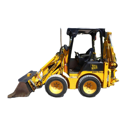
Koyker 510 User manual

OWNERS MANUAL
MANUAL NO. 670209
LOADER
IMPORTANT-KOYKER DEALER
BE SURE THIS MANUAL IS GIVEN TO THE
PURCHASER FOR FUTURE REFERENCE
KOYKER MANUFACTURING CO., P.O. BOX 409
LENNOX, SD 57039
11/15/2013


CONTENTS
CONTENTS PAGE
Introduction............................................................................................................................................ 1
SAFETY INFORMATION
Safety Alert Symbol............................................................................................................................... 2
Safety Information ...............................................................................................................................3-5
Safety Decals ......................................................................................................................................... 6
Tractor & Safety Pointers ...................................................................................................................... 7
ASSEMBLY INSTRUCTIONS
Attaching Loader ................................................................................................................................... 8
Attaching Fast Attach Bucket................................................................................................................ 9
Attaching Euro Bucket.......................................................................................................................... 10
Detaching Loader.................................................................................................................................. 11
Detaching Fast Attach Bucket .............................................................................................................. 12
Detaching Euro Bucket......................................................................................................................... 13
OPERATING INSTRUCTIONS
Operation............................................................................................................................................... 14
SERVICE AND MAINTENANCE
Specifications........................................................................................................................................ 15
Loader Inspection, Service, and Maintenance...................................................................................... 16
Hydraulic System Parts Diagram.......................................................................................................... 17
Hydraulic System Parts List.................................................................................................................. 18
“510” Loader Parts Diagram................................................................................................................. 19
Parts Identification Schedule ..............................................................................................................20-21
Fast Attach Adapter Parts Diagram & Schedule................................................................................... 22
Fast Attach Bucket Parts Diagram........................................................................................................ 23
Fast Attach Bucket Parts Schedule ....................................................................................................... 24
Euro Adapter Parts Diagram & Schedule............................................................................................. 25
Euro Bucket Parts Diagram .................................................................................................................. 26
Euro Bucket Parts Schedule (Grapple Compatible).............................................................................. 27
Euro Bucket Parts Schedule (Grapple Non-Compatible) ..................................................................... 28
Hydraulic Cylinder Information ........................................................................................................... 29
Hydraulics Information......................................................................................................................... 30
3” Cylinder Service Kit......................................................................................................................... 31
Hydraulic Cylinder Parts List ............................................................................................................... 32
Hydraulic Cylinder Parts Diagram........................................................................................................ 33
Piston and Gland Diagram ................................................................................................................... 34
LIMITED WARRANTY INFORMATION
Limited Warranty.................................................................................................................................. 35
TORQUE SPECIFICATIONS
Torque Specifications ........................................................................................................................... 36


INTRODUCTION
During a considerable period of time, Koyker Manufacturing Company of Lennox, South Dakota, made a
study of the farm loader industry and concluded that the farmer needs a loader that provides fast
attachment, quality, dependability, few parts, ruggedness, good delivery, and ease of maintenance, all at a
fair price. The fast attaching “510” Farm Loader has achieved these goals. With proper care and handling,
it will give many years of good service in normal farm operations.
Please be sure to follow the manual and give it proper care.
TO THE PURCHASER
You have purchased an excellent product. With proper care and use, it will give you years of good safe
service. Use only KOYKER or KOYKER approved parts in the general maintenance and repair of your
equipment. Please fill out ownership registration card as soon as possible.
Should you have any questions, comments, improvements, or suggestions regarding the contents of any of
the manuals provided, please contact Koyker Manufacturing Company. (800-456-1107 or E-mail
koyker@koykermfg.com)
We care about your safety!
Remember ALL safety decals are no charge from the factory. Please replace all safety decals if
missing or damaged. Your safety in important to us.
Page 1

SAFETYALERT SYMBOL
The symbol shown below is used to call your attention to instructions concerning your personal safety.
Watch for this symbol it points out important safety precautions. It means ATTENTION! Become Alert!
Your Personal Safety Is Involved!
Read the message that follows and be alert to the possibility of personal injury or death.
DANGER: Indicates an imminently hazardous situation that, if not avoided, will result in death or serious
injury.
WARNING: Indicates a potentially hazardous situation that, if not avoided, could result in death or
serious injury.
CAUTION: Indicates a potentially hazardous situation that, if not avoided may result in minor or
moderate injury.
WARNING!
Anyone who will operate or work around a front-end loader should first read this
manual.
Page 2

SAFETY
Improper use of a loader can cause serious injury or death. The following safety precautions, and those
given on the tractor mount installation instructions, should be thoroughly understood before attempting to
operate this machine.
BEFORE OPERATING:
Carefully study and understand this manual, the specific tractor mount instructions, and the
attachment(s) manual(s).
Prior to operation, inspect the loader for system leaks and damaged, missing, or malfunctioning
components in an effort to avoid the possibility of a dangerous failure involving structural
members or hydraulic system components.
Be certain any repairs necessary are completed prior to loader operation.
Follow recommended maintenance procedures and precautions on Page 13.
Completely familiarize yourself and others involved with the operation of the hydraulic control
valve before operating the loader.
Be certain all bystanders are clear of the machine and operation area prior to operation.
It may be necessary to add wheel ballast or rear weights as recommended by the tractor
manufacturer to maintain stability of the machine to prevent tipping or upset which could result in
serious injury or death. See mounting instructions for specific information.
It is recommended that both front and rear wheel treads be set to the widest recommended width to
prevent tipping or upset which could result in serious injury or death.
This loader is designed for farm type operations such as snow removal, barn and feedlot cleaning,
light commercial or light grading and digging. It’s design is NOT intended for industrial use.
DURING OPERATION:
Never operate the machine other than from the tractor operator’s seat.
Be sure operating area is clear of others during machine operations.
Never lift, hoist, or carry humans in the bucket or on any portion of the loader or loader
attachments. Failure to heed, may result in serious injury or death.
Page 3

SAFETY CONTINUED
Transport the machine load at the slowest speed possible and with the loader boom at the lowest
transport position to avoid tipping or upsetting, which may result in serious injury or death.
Be extremely careful when working on inclines or near loose fill, rocks, and holes as they can cause
tipping or upsetting which may result in serious injury or death.
Be certain to avoid overhead electrical wires when operating loader. Contact with power lines may
cause serious injury or death.
Avoid sudden stops when lowering or lifting the loader boom to prevent loss of control over the
machine and/or load, which may result in serious injury or death.
Use maximum ballast and the widest recommended wheel setting on your tractor when handling
large shiftable loads.
Never attempt to ram with the bucket at high speed or full tractor power. Sudden impact may result
in structural failure and possible serious injury or death.
Never adjust or perform maintenance on the loader or tractor with the unit in motion, or without
power source locked out.
Never get under bucket or lift arms or reach through the lift arms or bucket linkage when the loader
is in operation. Inadvertent movement may cause serious injury or death.
FOLLOWING OPERATION:
Whenever the machine is not in operation, lower the loader boom and set the tractor brakes,
disengage drive, shut the engine off, and remove the ignition key before dismounting the tractor.
If loader is to be disengaged from tractor, be sure the loader is securely supported on a hard, level
surface and the stand is securely engaged. Be certain all connections between tractor and loader are
free before disengaging.
TRANSPORTING:
Use safety lights and SMV emblem in addition to whatever local codes require when equipment is
being transported on the road or highway. Check with proper authorities for legal limitations.
Transport all loads at a slow and safe speed.
Carry the load as low as possible and maintain adequate visibility and good round clearance at all
times.
Page 4

SAFETY CONTINUED
PERFORMING MAINTENANCE:
Carefully review, understand, and follow the “maintenance” section in this owners manual before
attempting to service loader.
Lower the bucket or attachment to the ground, shut off tractor engine, and relieve pressure in the
hydraulic system before adjusting, lubricating, or servicing the loader.
Escaping hydraulic oil under pressure can penetrate the skin. Never use any part of your body to
check for hydraulic leaks. Use cardboard when checking for leaks. See Fig. 5-1. Relieve hydrau-
lic pressure before disconnecting any hydraulic line. Failure to heed may result in serious injury or
death.
Before disconnecting hydraulic lines, lower the loader and attachments. Lock out the hydraulic
supply and relieve all hydraulic pressure.
Replace any damaged or painted-over decals. See Page 8 for replacement decals.
REMEMBER:
1. Move Slowly!
2. Always use care and common sense!
3. Be careful for your own sake and for that of others!
4. Koyker Mfg. Co. includes all reasonable means for accident prevention except a safe and
careful operator.
FIG. 5-1
Page 5

SAFETY DECALS
Page 6

The use of good judgment and common sense is necessary by the operator in using this loader. The front
and rear wheels should be set for the widest wheel tread to assure best stability. Use extra caution when
rear wheel weights and tire ballast are added to a loader-equipped tractor. DO NOT ram into frozen dirt
piles, frozen manure piles, ice, etc., with great momentum where sudden shock loads are encountered.
Serious and costly damage may result to both the loader and the tractor.
When scraping or back dragging do not extend the attachment cylinders more than one half of the
cylinder’s stroke. A limited amount of leveling may be done, when the loader valving is arranged with a
float control. This will prevent damage to cylinder rods. Never ride in the bucket.
Before operating the loader, be sure no one is standing near it. Only one person, the operator, should be on
the tractor. Remain at the controls and under no circumstances leave the tractor unattended with the bucket
in a raised position.
Never lift a person in the bucket or walk under a raised bucket.
Never drive your loader-equipped tractor down a hill that is steeper than 15 degrees. Carry all loads low
and use care on side hills.
Always keep unused PTO shaft clutch levers disengaged.
Keep hands, feet, and clothing away from all moving parts.
Hydraulic oil, under pressure, can cause injury. Be sure that all connections are tight and that all pressure
is relieved before disconnecting any lines.
Care must be taken with your loader cylinders. Nicks, scratches, rust, or other shaft damage can result in
worn packing causing cylinder leakage and subnormal performance.
MOVE SLOWLY
USE COMMON SENSE
BE CAREFUL FOR YOUR OWN SAKE AND THAT OF OTHER PEOPLE
TRACTOR & SAFETY POINTERS
Page 7

ATTACHING LOADER
IMPORTANT:
Never attempt loader attachment on grades which are not reasonably level.
1. Check to be sure that the top surface of both mounting plates are free of bolts, screws or other
obstructions.
2. Drive the tractor carefully between the loader arms far enough to permit hookup of the hydraulic
hoses.
3. Once the hoses have been properly coupled, drive the tractor forward into the loader making sure
the loader members clear all parts of the tractor.
4. Use the bucket cylinders and lift cylinders to align the front yoke of the loader with the yoke
receiver on the tractor. Drive forward until the yoke is fully engaged into the receiver.
5. Use the bucket and lift cylinders to rotate the uprights back onto the mount plates. Make sure the
locator pins fully engage into the holes on the mount plates.
6. To secure loader, install the 3/4 x 2” Grade 8 bolts (included in mount kit) through the mount plate
and into the upright.
7. Prior to operation, be certain to review all safety and operation information contained within this
manual.
Page 8

ATTACHING THE FASTATTACH BUCKET
Page 9
1. For pin on buckets, assemble pins and retaining bolts as shown in the Parts Diagram of this manual.
Make sure all retaining bolts are secure and lubricate necessary points. Inspect pin and bolts
periodically for tightness and wear.
2. For Fast Attach Buckets, first tilt the bucket adapter forward so the top round pipe slides into the
receiver on the bucket (Fig. 9-1). Rotate the bucket back so the two rear pins line up with the holes
on the base plates of the bucket (Fig. 9-2). Turn both pins on bucket adapter so they drop through
the holes in the base plate of the bucket (Fig. 9-3). Put #6 hitch pin in place (Fig 9-4).
Fig 9-3
Fig 9-1 Fig 9-2
Fig 9-4

ATTACHING THE EURO BUCKET
Page 10
1. Prior to attaching the bucket, prepare the adapter for engagement by pulling the adapter handle
back (towards the operator) into it’s cocked position. With the bucket positioned on level ground,
tilt the bucket adapter forward approximately 45º. (Fig 10-1) Slowly drive forward into the bucket,
centering the adapter with the bucket as you go and position the top mount bar of the adapter
just below the hooks on the back side of the bucket. (Fig 10-2) Slowly raise the loader paying
attention that both hooks are engaged. With the top mount bar fully engaged, slowly roll the
bucket back. The bottom mount bar of the adapter will come in contact with the bottom of the
bucket. (Fig 10-3) Place the handle back in its engaged position (Fig 10-4). Ensure that the pins are
fully engaged thru the bottom hooks on the bucket.
Fig 10-2Fig 10-1
Fig 10-3
Fig 10-4

DETACHING LOADER
Page 11

DETACHING THE FASTATTACH BUCKET
Page 12
1. With the bucket resting on the ground, first remove #6 Hitch pin clip (Fig 12-1). Then lift and turn
both pins on the bucket so that they rest on top of the Latch Stop Pin (Fig 12-2). Put the #6 Hitch pin
clip back in place to prevent the locking pins from engaging (Fig 12-3). Slowly lower and dump your
way out of the bucket (Fig 12-4). Slowly back away from the bucket until you are clear of the bucket
and safe to maneuver.
Fig 12-1 Fig 12-2
Fig 12-3 Fig 12-4

DETACHING THE EURO BUCKET
Page 13
1. Prior to detaching the bucket, prepare the adapter for disengagement by pulling the adapter handle back
(towards the operator) into it’s cocked position (Fig 13-1) . The bucket should be resting on level
ground (Fig 13-2). Slowly lower and dump your way out of the bucket (Fig 13-3). Slowly back away
from the bucket until you are clear of the bucket and safe to maneuver (Fig 13-4).
Fig 13-1
Fig 13-2
Fig 13-3 Fig 13-4

OPERATION
WARNING:
Never allow anyone to operate the loader until they have carefully reviewed and
understood this owners manual.
FILLING THE BUCKET:
When manure is piled on a slope, it is best to drive tractor up the slope straight into the pile. Operating
sideways on a slope has a tendency to tip the loading unit. Drive tractor straight into the pile, raise the
bucket about six inches, then drop bucket and drive forward until the bucket is filled. Tilt bucket
completely back, raise main frame and back away from manure pile.
DUMPING THE BUCKET:
When dumping, bring the bucket to proper dumping height which is just high enough so it will not strike
the spreader as the load is being dumped. With the bucket tipped, drive tractor forward and raise the
bucket at the same time to distribute the load evenly into spreader or conveyance.
RAISING THE BUCKET:
WARNING:
Make sure material in bucket cannot spill out on to tractor when loader boom is raised.
Keep clear of overhead obstructions such as trees, limbs or power lines when raising
the bucket.
Side cutting is the best method of reducing large stockpiles. If the sides of the pile are
too high, use the loader to pull them down and reduce the possibility of slides.
Make sure you keep all lines, cylinders, and complete hydraulic system free of all sand, dirt, and
foreign matter. Use only clean oil in the hydraulic system. When removing the loader from the
tractor, be sure to plug all open ports. If the loader will be out of service for several days or longer,
grease the exposed polished piston shafts on the bucket and the lift cylinders.
WARNING:
NEVER attempt to operate the loader with someone near the loader frame or bucket.
If this loader is equipped with a Grapple fork, be sure Grapple teeth are closed before leaving seat of
tractor.
Page 14

SPECIFICATIONS
Page 15
KOYKER 510 LOADER SPECIFICATIONS
Description of Equipment Rated
Loader Model..................................................................................................................... 510
Attachment Adapter & Bucket Size.....................................................................................6’
Rated Flow......................................................................................................................20 GPM
Maximum Pressure ........................................................................................................2500 PSI
Lift Cylinder Dia.............................................................................................................3” Bore
Attachment Cylinder Dia................................................................................................3” Bore
Tractor Horsepower Range...........................................................................................60-160 HP
Dimensional Specifications
(A) *Maximum Lift Height to Pivot Pin......................................................................... 12’ 10”
(B) *Lift Height under Level Bucket..................................................................................12’
(C) *Clearance with Bucket Fully Dumped........................................................................10’
(D) *Reach at Maximum Lift Height................................................................................ 3’ 1”
(E) Maximum Dump Angle................................................................................................45°
(F) *Reach with Bucket on Ground.................................................................................. 6’ 1”
(G) Maximum Rollback Angle...........................................................................................28°
(H) *Digging Depth.............................................................................................................9”
(J) *Overall Height in Carry Position.............................................................................. 5’ 10”
Operational Specifications
(U) *Lift Capacity to Maximum Height at Pivot Pin ....................................................5540 lbs.
(V) *Lift Capacity to Maximum Height 31.5” Forward of Pivot Pin............................3850 lbs.
(Y) *Breakout Force at Ground Line at Pivot Pin........................................................10300 lbs.
(Z) *Breakout Force at Ground Line 31.5” Forward of Pivot Pin.................................7820 lbs.
*Raising Time................................................................................................................7 seconds
*Lower Time..................................................................................................................5 seconds
*Attachment Dumping Time .........................................................................................5 seconds
*Attachment Rollback Time..........................................................................................3 seconds
*Specifications based on ASABE standards S301.3 (Front-End Agricultural Loader Ratings) The above
information is based on testing done by Koyker Mfg. Variations in maximum lift height and other specs for
different tractors are due to tire sizes, variations in loader mounting locations and hydraulic system
efficiency.
Specifications are subject to change without notice and without liability therefore.

LOADER INSPECTION, SERVICE, AND MAINTENANCE
Lower the bucket to the ground, shut off tractor engine, and relieve the pressure in the hydraulic
system before adjusting, lubricating, or servicing the loader.
Inspect all pins and grease fittings before each use and lubricate with heavy duty grease as
indicated in this manual.
Periodically check all bolts for looseness and re-torque if necessary.
Before storage, be certain all hydraulic cylinders are fully collapsed so that the rod will not be
exposed to the elements or damaged.
Be certain hydraulic system remains sealed at all times to prevent contamination.
Check and maintain an adequate fluid level in the tractor reservoir prior to use.
Inspect all hydraulic system hoses and fittings. Replace prior to further operation if damaged.
WARNING!
Escaping hydraulic oil under pressure can penetrate the skin. Never use body to
check for hydraulic leaks. Use cardboard when checking for leaks. See Fig. 13-1.
Relieve hydraulic pressure before disconnecting any hydraulic line. Failure to
heed may result in serious injury or death.
FIG. 13-1
Page 16

HYDRAULIC SYSTEM PARTS DIAGRAM
Page 17
Table of contents
Other Koyker Compact Loader manuals
Popular Compact Loader manuals by other brands

Worldwide Construction And Forestry Division
Worldwide Construction And Forestry Division 444K Technical manual

Komatsu
Komatsu WA500-6H Operation & maintenance manual

Nortrac
Nortrac 20 HP Mini-Track Gas Loader owner's manual

Southworth
Southworth PalletPal Stack-n-Go FPS3000-43 NAS owner's manual

jcb
jcb 407 Quick reference guide

Toro
Toro 22305 Operator's manual