ATTACK 13212 User manual

Owners Manual
ATTACK13212

Important Safety Information 3-4
Before You Start 5
Assembly Instruction
Console Instruction
Parts List
Exploded View
6-10
11-13
14-16
17

WARNING! Before using this bike or starting any exercise programme, consult your appropriate
medical practioner. This is especially important for persons of a senior age and/or persons who
have not exercised recently and/or persons with pre-existing health problems. The manufacturer
or distributor assumes no responsibility for personal injury or property damage sustained by or
through the use of this product.
SAFETY PRECAUTIONS AND TIPS
1. It is the owner's responsibility to ensure that all users of this bike have read the Owner's Manual
and are familiar with warnings and safety precautions.
2. This bike has a user maximum weight capacity of 300 pounds. (136 Kilograms)
motion, the pedals will be in motion. Do not attempt to stop the bike by applying backward
pressure to pedals while they are turning as injury may occur.
4. Do not attempt to turn the pedal cranks by hand. Do not touch any driving
mechanism while the bike is in motion as possible injury could occur.
5. In a home setting, keep children away from the bike when it is not in use. Keep children
and pets away from the bike while it is in use.
6. Do not attempt to perform dip movements on handlebars.
7. The bike should only be used on a level surface and is intended for indoor use only. It should not
be placed in a garage, patio, or near water and should never be used while you are wet.
8. Wear comfortable, good-quality walking or running shoes and appropriate clothing. Do not
use the bike with bare feet, sandals, socks or stockings.
9. Always examine your bike before using to ensure all parts are in working order.
10. Allow the bike to fully stop before dismounting.
11. Pets should never be allowed near the bike.
12. Do not leave children unsupervised near or on the bike.
13. Never operate the bike where oxygen is being administered, or where aerosol products are
being used.
14. Never insert any object or body parts into any opening on the bike.
15. For safety and to prevent damage to your bike, no more than one person should use it at any
time.
16. Service to your bike should only be performed by an authorised service representative, unless
authorised and/or instructed by the manufacturer.
17. Failure to follow these instructions will void the unit warranty.

Before You Start
Thank you for purchasing this new AIR BIKE !! This quality product you have chosen was designed to
meet your needs for cardiovascular exercise. Before you start, please read the owner's manual and
become familiar with the operation of your new bike.
Proper installation and regular maintenance are required to ensure user’s safety. Maintenance is
the sole responsibility of the owner.
Remember to take the time to perform the stretching exercises provided to avoid injury.
If you are taking medication, consult with your medical practitioner to see if the medication will
If you have heart problems, you are not active, and/or of a senior age, do not use the pre-set
your medical practitioner.
To avoid the risk of electrical shock, always keep the console dry. Do not spill liquids on the console.
We recommend a sealed water bottle for beverages consumed while using the bike.
Please review the following drawing below to familiarise yourself with the listed parts.

Assembly Instruction
FIGURE 1: Stabilizers Assembly STEP 1
(D03) four spring washer (D06) and four screws (B06) as show on the diagram below .
NOTE:
1. Each stabilizer (A06 & A07) have two foot adjusters (E10) You can turn foot adjusters to adjust
each side balance for the bike when the ground is uneven.
Assembly Instruction (A01) before riding on the bike.
Remove All Security Wrapping
And Tape Before Beginning

Assembly Instruction
Step 1: Install the right handlebar assembly (A02) onto the U shape tube of the main frame (A01) by
threading the back part of the foot peg into the position A. Then hold the foot peg and turn
clockwise until tight with an Allen Key.
(B14) two washers (D01), the bearing (E24) and one nylock nut (C02) as shown as in the
drawing below.
Step 3: Repeat step1 through step 2 for the left side assembly.
FIGURE 2: Right & Left Handlebars Assembly

Assembly Instruction
FIGURE 3: Right & Left Pedals Assembly
Step 1: Thread the right pedal (G11) into the hole of the right crank (E05). Secure in place by turning it
clockwise to tighten.
Note: Right pedal (G11) is marked with an “R”.
Step 2: Thread the left pedal (G10) into the hole of the left crank (E04). Secure in place by turning it
clock wise to tighten.
Note: Left Pedal (G10) is marked with an “L”
the lock nuts beside the seat pad to tighten
Assembly Instruction
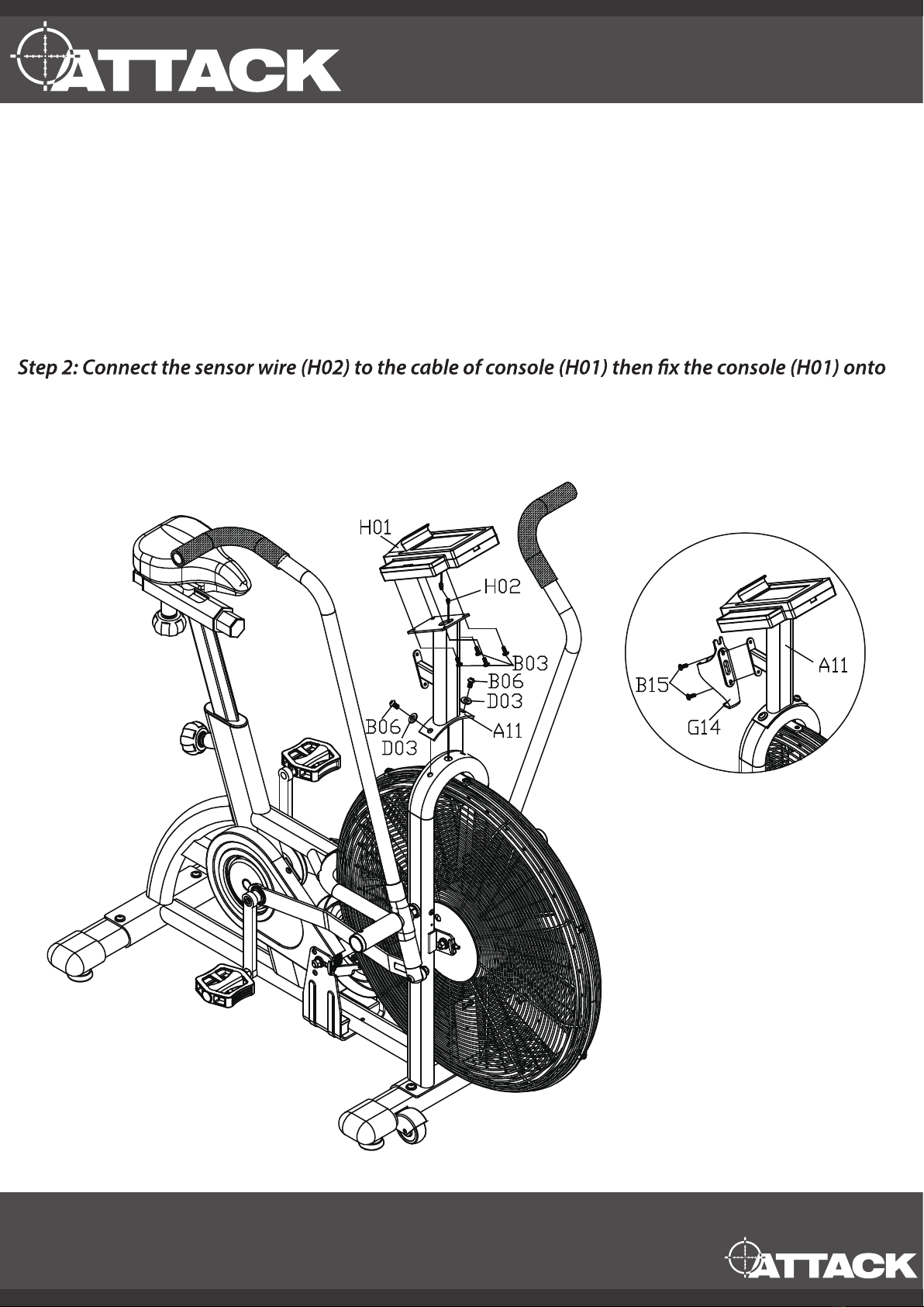
FIGURE 4: Monitor & Water Bottle Holder Assembly Step
Step 1: Thread the sensor wire (H02) which is out from the main frame (A01) through the
console mast (A11) until it reaches the top opening of the console mast (A11)
Assemble the console mast (A11) onto the main frame (A01) with two screws (B06) and two
washers (D03) as show in the below picture.
the console mast (A11) as per the four screws (B03).
Step 3: Fix the water bottle holder (G14) to the console mast (A11) with two screws (B15).

Congratulations!
You have completed the assembly of your new Air Bike!

START:Press “Start” to enter ready mode, then choose the desired programme and
also push this key to end the pause situation.
STOP : Press “Stop” for 1or 2 secs. This will cause the programmes to halt
temporarily. After 2 seconds of pressing all data will be cleared and settings will go back
to ready mode.
ENTER : Press “Enter key” to con rm all your desired values.
UP & DOWN : Set your desired value by pressing the UP or Down key.
Note: The ready mode is showing and skipping o the value on the screen. The sleep
mode is showing
Console Instruction
Key Functions:
How to Operate
1st press the START key then press UP/DOWN keys to set the users age, then press ENTER to
2nd press the START key to start exercise for manual operation. Or select programme (7
Programmes) on the right side of the console for exercise.

THE INTERVAL DISPLAY PANEL
Programme:
Interval 20/10 (Work:20 seconds, rest:10 seconds)
Interval 10/20 (Work:10 seconds, rest:20 seconds)
Interval User
The above three programmes all displayed on this interval display panel.
(A) The upper banner will signal which interval programme is running and tell you whether
the currently running interval is a work or rest period. (Programme (1) and (2) work and
rest interval are set to 8 circles, while the programme (3) is 1 circle pre-set)
(B) The Total Time display will count up the total programme run time while the large
numeric display will count up the work or rest segment time.
(C) The 88/88 Display -- will show the current interval and the total number of intervals in
the programme.
THE TARGET TIME, DISTANCE & CALORIES DISPLAY PANEL
Target Time
Target Distance will be displayed in miles or kilometres depending upon how the console
was programmed during the initial setup.
Target Calories will track the number of calories burned during the work out.
Three programmes all displayed on this target display panel.
A top banner shown as right diagram will signify which target programme is running
Programme:
WATTS/ SPEED / RPM DISPLAY
Regular display: Watt, speed, RPM. The above will be displayed during all programmes
Watts are a measurement of energy generation and will track the amount of work
generated at any given time during a workout.
Speed display will post a value which simulates that of riding a standard bicycle and is
derivative of the current RPM or pedal speed.
RPM relates to the speed at which the cranks are spinning
Under active situation: Watts, Speed and RPM will offer currently active value.
Under pause mode or stop situation: Watt, speed and RPM display will show the max
value, summarized value and average value
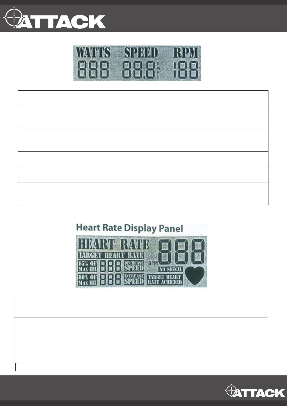
HEART RATE DISPLAY PANEL
This console has a implanted wireless receiver, so pulse can be read per wearing wireless
pulse belt ( optional accessory)
When the user’s pulse is detected by the console, it will display the current heart rate value
and the heart icon will flash. There is BPM range control, from 65% of max HR to 80% of
max HR. The users target heart rate value will bring out the BPM range, and SPEED
BANNER (increase or decrease) will signal the user to speed up or slow down when they
are not in the BPM range. When the user’s heart rate is within the target range, the target
heart rate achieved banner will post.
+44 01538 387960

ADDITION INFORMATION:
In any condition, press the “stop” key for over 2 seconds. This will reset this console.
After 30 seconds of not touching the keys on the console the console will go into sleep
mode.
The console will be active if any key is pressed during the sleep mode.
The preset pause situation is only 1 minute long, after 1 minute the console will enter sleep
mode. The user can press “ start” mode to start the training again.
Once the user stops running the console will sense no RPM for over 1 minute and will then
automatically go into sleep mode
The switch for Kilometres to miles is available by pressing “ Start key” and “Enter key”
simultaneously, then pressing “ Up “ or “ Down “ to chose the kilometres or miles. Finally
press “Enter “to confirm measurement.
+44 01538 387960

Part List
+44 01538 387960
ITEM
PART NAME
QTY
A01
Main Frame
1
A02
Right Handle Bar
1
A03
Left Handle Bar
1
A04
Chain Transmission Axle
1
A05
Linkage Arm
2
A06
Front Stabilizer
1
A07
Rear Stabilizer
1
A08
Seat Post
1
A09
Seat Post Slider
1
A10
Fan Steel Bracket Set
1
A11
Console Mast
1
A12
Fan Netting fixed plate
7
A13
*None*
*
B01
10x16x17mm Screw
7
B02
TP4x16L Screw (black)
1
B03
M5x10L Phillips Screw
4
B04
M5xP0.8x8L Phillips Screw (black)
7
B05
M5xP0.8x8L Phillips Screw (stainless)
1
B06
M8x20L Hex Round Head Screw (DIA 6mm)
6
B07
M8x45L Hex Round Head Screw (carbon)
2
B08
M22 x17x91.4 Hex Head Screw
2
B09
M6x12L Hex Head Screw (Loctite, silver)
4
B10
M6x16L Hex Head Screw (carbon , silver)
4
B11
M6x6L Hex Round Head Screw (black)
2
B12
Crank Fixing Bolt
3
B13 M6xP1.0x15L Socket Head Screw 4
B14 M10x40 Hex Flat Head Screw 2
B15
M5x12LHex Round Head Screw
2
B16
*None*
*
C01
3/8x26” Acorn Nut Cap
4
C02
M10 Nylon Nut (thin) (black)
2
C03
M14xP1.5 , R Locknut (Loctite)
2
C04
M6 Hex Nut (Black)
4
C05
M6 Nylon Nut (silver)
4
C06
M8 Nylon Nut (thick)
2
C07
* None*
*
C08
* None*
*
C09
M16 Hex Nut (thin)( black
2

D01
10x19x2.0t Washer (black)
4
D02
16x21.8x2.0t Washer ( black)
2
D03
8x19x1.0t Washer (black)
10
D04
5x1t Spring Washer (black)
7
D05
6x1t Spring Washer (black)
4
D06
8x2t Spring Washer (black)
4
D07
* None *
*
D08
16x21.8x1.0t Washer ( black)
2
E01
Foot Peg (38.4x32x110.6mm)
2
E02
Crank Fixed Round Plate (L)
1
E03
Crank Fixed Round Plate( R)
1
E04
Left Crank
1
E05
Right Crank
1
E06
Seat Fixing Rod
1
E07
C Retainer ( S-20)
1
E08
Adjustment Channel
4
E09
Pop Pin Knob
2
E10
Foot Adjuster
4
E11
Chain Tensioner
4
E12
#6004 Precise Bearing
2
E13
#6803 Precise Bearing
8
E14
#99502ZZ Ball Bearing
2
E15
Cir –Clip
4
E16
* None *
*
E17
Inner Lock Tablet (
ψ
23*ψ9*23L)
1
E18
Inner Lock Tablet (
ψψ
23*ψ9*37.5L)
1
E19
Front Chain Wheel
1
E20
*None*
*
E21
*None*
*
E22
Rear Chain Wheel
1
E23
*None*
*
E24
POS10 Bearing (M16x1.5)
2
F01
Chain Guard (Left)
1
F02
Chain Guard (Right )
1
F03
Fan Cage (Left )
1
F04
Fan Cage (Right )
1
G01
Transportation Wheel
2
G02
Seat Post Support Bushing
1
G03
DIA 50 Hex End Plug
2

G07
V-Belt
1
G08
Fan Cage Cover (Left )
1
G09
Fan Cage Cover (Right )
1
G10
Left Pedal
1
G11
Right Pedal
1
G12
Seat Pad
1
G13
Stabilizer End Cap
4
G14
Water Bottle Holder
1
G15
*None*
*
G16
Steel Chain
1
G17
*None*
*
G18
*None*
*
G19
Wire Plug
1
H01
Console
1
H02
Sensor Wire
1
H03
Magnet
1
G04
Seat Fixed Hex Spacer
1
G05
DIA38 Hex End Plug
2
G06
Handlebar Sleeve
2

Exploded Drawing
+44 01538 387960
Table of contents
Popular Exercise Bike manuals by other brands


Sportplus
Sportplus SP-HT-0001 user manual

Tunturi
Tunturi Star Fit X100 X-Bike user manual

NordicTrack
NordicTrack Gx4.1 Bike HASZNALATI UTASITAS

Sunny Health & Fitness
Sunny Health & Fitness P8150 user manual

Weslo
Weslo Easy Fit WLIVEX57010.0 user manual

Sport-thieme
Sport-thieme H700ST Instructions for assembly and use


