ATV ATV110-M User manual


BRIEF INTRODUCTION TO FOUR-WHEELED
CROSS-COUNTRY VEHICLE MODELATV110-M
Four-wheeled cross -country vehicle, modelATV110-M is a full road condition vehicle
which can be driven on every kinds of road conditions such as sand beach, grassland, forest,
village,constructionsitecountryroad,This maintenancemanualoffour-wheeledvehiclemodel
ATV110-M(Hereaftercalledcross-countryvehicleforshort) compiledbyChongqingIndus-
tries Co., Ltd is specially provided for saler and technical staff of our Group. This manual
mainlyintroducethemaintenance,removingandrepairingmethodofcross-countryvehicleand
providesomerelativetechnologyandperformancedata.Becausethismanualcan’tcollectthe
wholecontentofcross-countryvehicle,itcan only help maintainer of our groupandit’ssaler
haveabasicunderstanding on working principle, maintenanceprocedureandrepairing tech-
nologyofcross-countryvehicle.Ifyoudon’thavethisknowledge,whenrepairingcross-coun-
tryvehicle,theconditionofimproperassemblinganddangeroccursafterassemblingareeasily
happened. Proper operation and maintenance are the advance of your safely driving cross-
country vehicle, it also can reduce the troubles of cross-country vehicle and keep the best
performance of it. The specification, performance and explanation stated in the manual are
determined according to newly design of the vehicle, which are subject to changes without
notce.
Inthismanual,forspeciallyimportant requirement,thewordsof“Warning”“Caution”are
labelledtopromptrelativemaintainer toabideit.
Inthemanual
Caution
Showthatif thecontentof“Warning”isn’tobeyed, thedriver,maintainer,
checkerwillbeheavilyinjuried,evendead.
Showthatyoumust be carefultopreventthe vehicle from beingdamaged.
Warning
Maintenancemanualoffour-wheeledcross-countryvehiclemodelATV110-M
Firstedition Aujust 2005
This manual is published by publishing factory. maintain the copyright of
publishing. Without permitted, publishing is prohibited.

Content
Content ...............................................................................................................................................I
Chapter I General description..............................................................................................................1
Section 1 Description ..........................................................................................................................1
Section 2 Special tools, instruments & meters ....................................................................................2
(I) Special tools ........................................................................................................................2
(II) Instruments & tools ...........................................................................................................3
Section 3 Identification code, label of model and engine No. .............................................................4
Section 4 Points for attention in maintenance..................................................................................... 4
Section 5 Specification ........................................................................................................................8
I. How to use conversion table of unit ....................................................................................8
(1)How to use conversion table...............................................................................................8
(2)Definition of unit .................................................................................................................8
II. Basic specification...............................................................................................................9
III.ATV body...........................................................................................................................10
V. Maintenance specification of engine ..................................................................................11
Section 6 Wiring diagram ofATV........................................................................................................14
Section 7 Requirements for torque of fastener ....................................................................................15
Section 8 Lubrication ..........................................................................................................................16
Section 9 Lubrication point and type of lubricants .............................................................................17
(1) Lubrication point and type of lubricants(ATV body).........................................................17
(2) Lubrication point and type of lubricants(Engine)...............................................................18
Chapter II Maintenance and adjustment of vehicle ............................................................................19
Section 1 Periodic maintenance/ lubrication .......................................................................................19
Section 2 Disassembly and assembly of cushion, fender and fuel tank..............................................20
(I) Cushion...............................................................................................................................20
(II) Rear fender.........................................................................................................................20
(III) Front fender .....................................................................................................................22
(IV)Fueltank ............................................................................................................................23

Section 3 Maintenance and adjustment of vehicle body ....................................................................26
(I) Wear inspection of front and rear brake ..............................................................................26
(II) Adjustment of front brake..................................................................................................26
(III)Adjustment of free clearance of left lever and rear brake pedal .........................................27
(IV) Inspection of steering system ..........................................................................................29
(V) Adjustment of toe-in of front wheel..................................................................................30
(VI) Adjustment of rear shock absorber ..................................................................................31
(VII)Inspection of tire ..............................................................................................................32
(VIII) Inspection of rim ............................................................................................................33
Section 4 Maintenance and adjustment of electrical appliance...........................................................34
(I) Inspection of battery...........................................................................................................34
(II) Inspection of fuse ..............................................................................................................35
Section 5 Maintenance and adjustment of engine ..............................................................................36
(I) Adjustment of clutch ..........................................................................................................36
(II) Clean of air filter .................................................................................................................36
(III) Inspection of spark plug ...................................................................................................37
(IV) Adjustment of idle speed..................................................................................................38
(V) Adjustment of free clearance of throttle grip .....................................................................38
(VI) Adjustment of speed limitator ..........................................................................................39
(VII) Adjustment of valve clearance ........................................................................................39
(VII) Inspection of ignition timing ...........................................................................................41
(IX) Measuring of compressive force ......................................................................................42
(X) Inspection oil quantity of engine.......................................................................................43
(XI) Replacement of engine oil and inspection of oil flow .......................................................44
Chapter III Repair and maintenance of vehicle body ..........................................................................46
Section 1 Rear driving gearcase and driving shaft..............................................................................46
(I) Disassembly ........................................................................................................................46
(II) Inspecting procedures .......................................................................................................48
(III) Installation procedure.......................................................................................................51
Section 2 Rear wheel/Rear brake/Rear wheel axle...............................................................................54
(I) Removal steps....................................................................................................................54

(II) Inspection steps ...............................................................................................................55
Section 3 Steering operation system..................................................................................................57
(I) Removal steps of steering bar............................................................................................57
(II) Removal steps of steering vertical column welding ..........................................................58
(III) Inspection content...........................................................................................................59
(IV) Installment steps..............................................................................................................60
(V) Installation steps of steering bar ......................................................................................63
Section 4 Front shock absorber and front wheel fork ........................................................................64
(I) Disassembly .......................................................................................................................64
(II) Inspection steps ...............................................................................................................65
(III) Installment steps..............................................................................................................66
Section 5 Rear shock absorber and rear wheel fork............................................................................69
Chapter IV Electric appliance .............................................................................................................70
Section 1 Inspect switch ....................................................................................................................70
(I) Inspect switch....................................................................................................................70
Section 2 check lamp(headlight) ........................................................................................................71
Section 3 Troubleshooting the ignition system failure ......................................................................75
Section 4 Troublshooting electric starting system ............................................................................76
Section 5 Check starting motor ..........................................................................................................79
Section 6 No charging in the battery .................................................................................................81
Section 7 Troubleshooting ................................................................................................................83
Section 8 Inspection of lighting system.............................................................................................85
Chapter V Engine ............................................................................................................................... 86
Section 1 Disassembly of engine ....................................................................................................... 86
(I) Remove the engine from finishedATV .............................................................................. 86
(II) Disassembly of engine......................................................................................................88
section 2 Inspection and maintenance of engine ............................................................................... 96
Chapter VI Vecicle ordinary trouble and its judgement ...................................................................... 116
(I) Starting trouble/difficulty................................................................................................... 116
(II) Poor idle speed performance............................................................................................. 117

(III) Poor middle and high speed performance........................................................................ 117
(IV) Shifting troubler ............................................................................................................... 117
(V) Clutch slips ....................................................................................................................... 118
(VI) Clutch is locked ............................................................................................................... 118
(VII) Engine is overheat .......................................................................................................... 118
(VIII)Brake trouble ................................................................................................................. 118
(IX) Shock absorber failure/improper operation ..................................................................... 118
(X) Lighting system ................................................................................................................ 119

Chapter IGeneral description
Section 1Description
1. Front wheel
2. Shift pedal
3. Fuel cock
4. Cushion
5. Rear wheel
6. Exhaust silencer
7. Rear fender
8. Rear brake pedal
9. Front fender
10. Bumper
11. Left lever of rear brake
12. Left switch unit
13. Fuel tank cover
14. Throttle grip
15. Right lever of front brake
Caution:
The ATV you purchased maybe slightly differ from the pictures in the manual due to im-
provement or other changement.
12345
67 8 109
11 12 13 14 15
-1-

Section 2 Special tools, instruments and meters
(I) Special tools
Special tools is the necessary tools used for accurately adjustment and assembly, it is
helpfultopreventthemaintenancedefectsandcomponentsdamagecausedbyusingimproper
tools.
1.Wrenchfor valve adjustment mainly usedforadjustingvalveclearance.Specification:
3mm 90890-01311
2.Pullerforpistonpin,mainlyusedofremovingpistionpin.
3.Removerfor rotator,mainlyusedforpulling magnetorotatorformcrank.
4.Clamp for rotator, mainlyused for clampingmagneto rotator whenremoving it to pre-
ventit’s rotationdue totorque force.
5.Stoprotatingmeterforrotator,mainlyusedforremovingandassemblingrotatorofkick
starter.
6.Pullerforcrank,mainlyusedfordisassemblingcrankfrom crankcase.
7.Pullerfor rocker shaft,mainlyusedforremovingrockershaft.
8.Compressing tools for spring of valve, mainly used for fixing and compressing spring
whenassemblingvalvelockclamp.
9. Assembling and disassembling tool for valve guide, mainly used for assembling and
disassembling valveguide.
10.Assemblingbuffer,mainlyusedforassemblingcrankandbalancinggear.
11.Hollowsleeve,mainlyusedforassemblingcrankandbalancinggear.
12.Assemblingtoalforcrank,mainlyusedforassemblingcrankandbalancinggear.
13.Assemblinganddisassemblingjointforuniversalcoupling,mainlyusedforassembling
anddismsemblinguniversalcoupling.
14.Assemblinganddisassemblingdisc,mainlyusedforassemblinganddisassembling re-
versegear.
15.Fixedpullerforgear,mainlyusedforassemblinganddisassemblinggear.
For the above tools, you can select with reference to special tools of the same type
of vehicle.
-2-

(II) Instruments and meters
The following instruments and meters can be selected with reference to the same type of
vehicle.
speedometer of engine
(90890-03113) multimeter
Ignition timing meter
(90890-03141) spark tester of spark plug
barometer ignition checker
measuring tool of gasoling
(90890-01312) dialindicator
-3-

Section 3 Identification code, label of model and engine N0.
Section 4 Points for attention in maintenance
der of disassembly, this in assembling, can
not only increase the assembling speed, but also
ensure the rightness of assembling.
2.Replace the components
When replacing the components, be sure to
use qualified products provided by use lubricants
and grease which brank is assigned by lubricate.
3.Oil seal, shim, o-ring clip split pin,
elastic washer.
3.1 When disassembling to maintain the
engine, in order to ensure that the reassembled
engine have good sealing and connecting part is
fixed and reliable, all the oil seal, shim, o-ring,
clip, split pin and elastic washer should be
replaced, be sure to keep lip of oil seal surface
of shim and o-ring in cleaning condition.
3.2 When reassembling, apply lubricants to
lubricate all the mated components and bearing,
apply grease for oil seal.
-4-
1.Preparation when disassembling
1.1 First clean the dirt, mud and attachment
on the vehicle befor removing or disassembling.
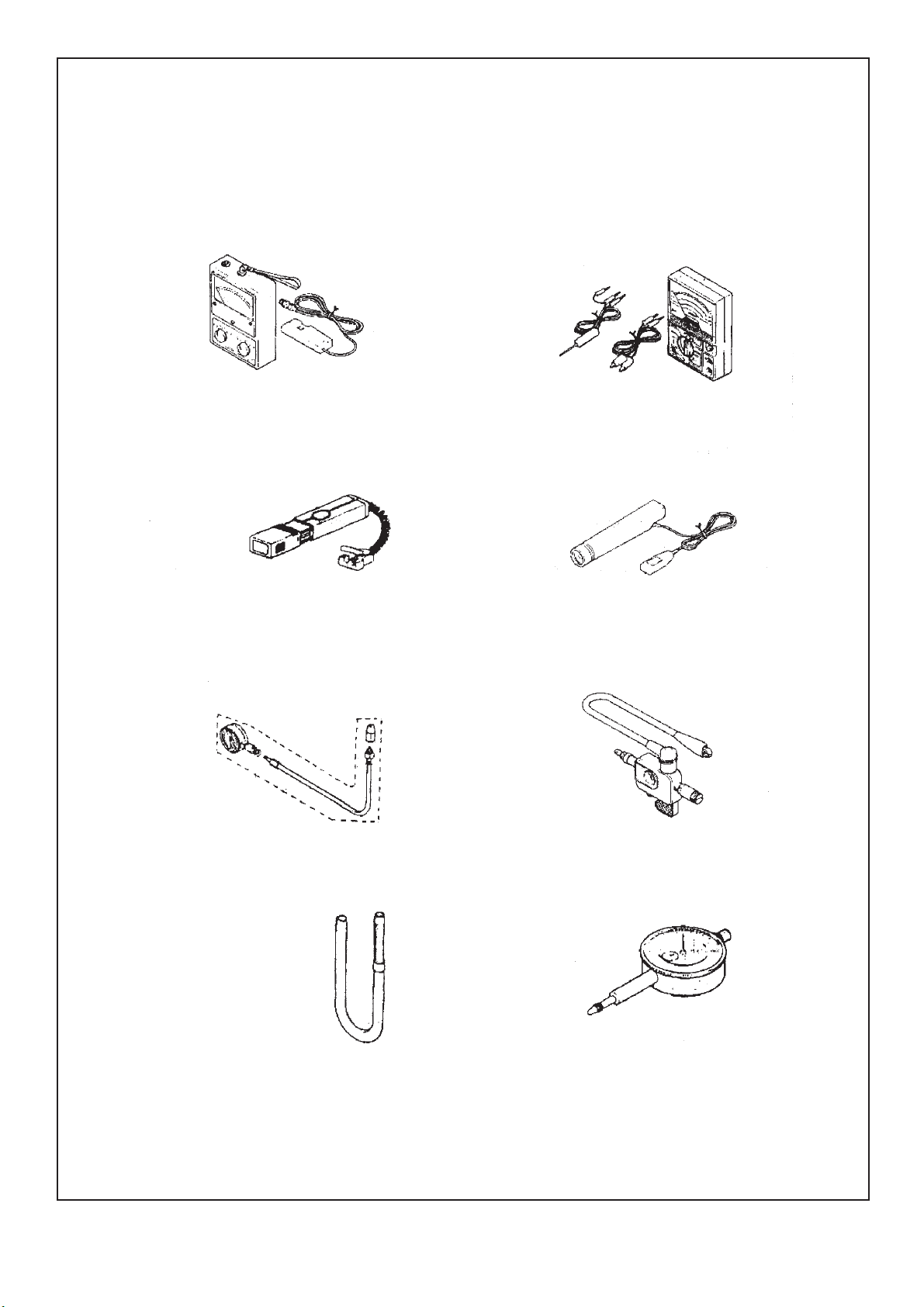
1.2 Use proper special too cleaning device
and means.
1.3 Keep all the components away from fire
source. Pay attention to the safety, Don’t be
burned by the high temperation portion of engine,
exhuaster and silencer etc. Be sure to take care
of each other when operation with other people.
1.4 When disassembling the ATV, put the
mated components, such as gear pairs, cylinder,
piston and other “mated” components by nor-
mal running in together, When assembling or
replacing these components, they should be in
pairs.
1.5 When disassembling the engine, clean
all the components and put in the tray in the or
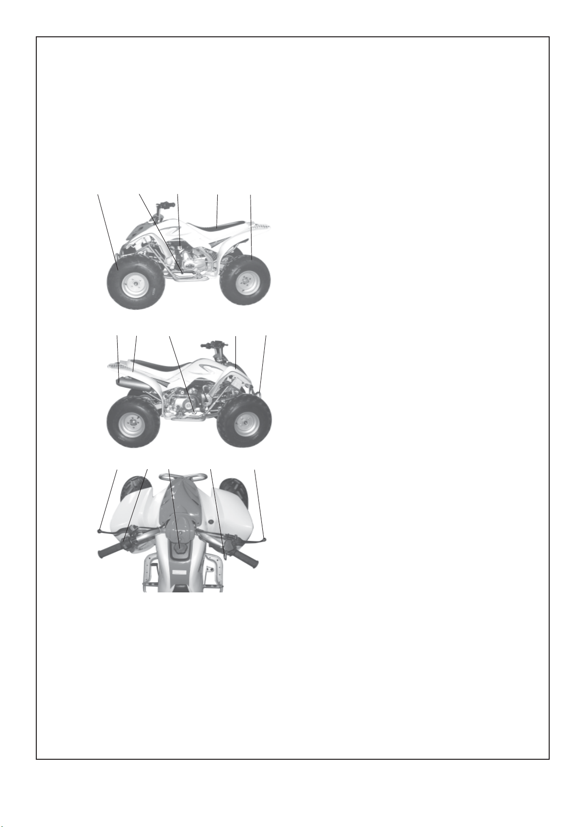
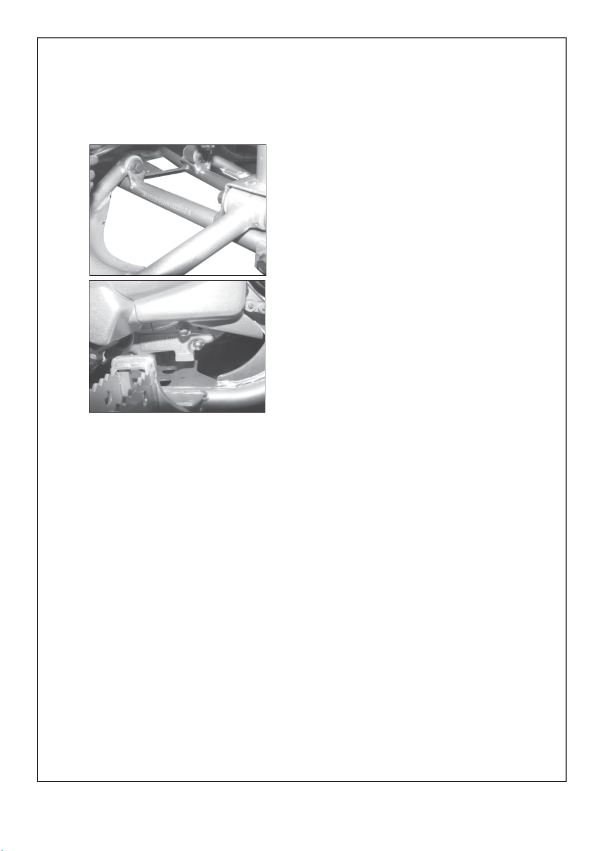
Identification code
It is engraved in the left or right side of front
supporting main take of engine of frame.
Engine N0.
The engine No. engrave onthe narrow point
position.

4. Clip
4.1Before assembling, be sure to check all
the clips carefully.Use a new one after remov-
ing the clip of piston pin. When mounting clip
ring ¢Ùmake the sharp face ¢Úon the opposite
position of impacted face ¢Ûof clip.(see left
fig)
5.Locking washer /shim and location pin
5.1When reassembling after disassembling.
be sure to replace all the locking washer /shim
and location pin @ After bolt or nut is fixed on
the locking position. be sure to bend and fix both
ends of locking shim along head of bolt or di-
rection of nut.
6.Bearing and oil seal
6.1 When assembling bearing and oil seal
put the mark or specification of manufacturer
outside, When assembling oil seal apply a thin
film of lithium-base grease on the lip of oil seal.
Caution:
Don’t blow to dry the inside of bearing with
compressed air, this would damage the surface
of bearing.
-5-

7.Check of electirc parts
7.1 Check the rust, dirt and moisture etc.
of connector, if there is moisture, please blow it
dry and clear the rust and dirt.
7.2 The eclectolyte inside the battery is a
kind of corrosive, when operation exercise shall
be taken not to let the electrolyte splash on the
body.
7.3 When repairing wire on electric parts,
first remove the wire on the termianl of nega-
tive pole of battery(see fig.7.1).When tighten-
ing or loosening bolt of terminal of big capacity
battery, don’t let the wrench contact with en-
gine or other metal parts of vehicle body to
avoid the electric shock.
7.4 When connecting the wire of battery,
first connect the opositive pole wire of battery,
then connect the negative pole wire After con-
necting the wire, apply clean grease on the ter-
minal to avoid the increasing of resistance due
to rust.
7.5 Check the terminal of connector
a Grip two terminals of connector together,
check with the multimeter.(see fig.7.3,fig.7.4)
Fig.7.1Removal of negative pole wire of battery
Fig.7.2 Connection of positive pole wire of battery
Fig.7.3
Fig.7.4
-6-

b. If joint is slack, bend the plug pin
upward, then connect with connector plug(see
fig7.5)
7.6 Before mounting new fuse, check if the
load of fuse of components is right, especially
for the portion being burned broken regularly,
then mount the fuse having proper current value.
7.7Wire connector have two kinds, one is
single-head connector, another is multi -head
one.Before connecting single-head connector ,
check if there is broken on the housing of joints,
the joint is fixed and if there is a broken phe-
nomenon on it. When inserting the joint, it should
be fixed, then put in plastic coating after
inserting.
In general, multi-head connector is plastic
one, and locking catch is designed. When disas-
sembling the connector, first open locking catch
when connecting again, first check if all the joint
is in good condition, if there is bent or twisted
on them. After connecting, align the locking
catch and lock them.
8. Use torque spanner to tighten screw and
nut, and as per specified torque to tighten them.
It should be tightened in steps from big ones to
small ones, from inside to outside and along the
direction of diagonal line to intersect. A s shown
in fig.8.1.
Fig.7.5
Fig.8.1Tightening method of screw and nut.
-7-
Plug pin
According to
intersecting

Section 5 Specification
(I) How to use conversion table of unit
(1)How to use conversion table
AllthespecifieddocumentsinthismanualaretakenSIandMetricasunit.Withthefollow-
ingconversiontable,metricunitcouldbeconversedintoimperialunit.
METRIC MULTIPLY IMPERIAL
mm 0.03937 in
2mm ¡À 0.03937 = 0.08in
Conversiontable
(2)Definitionofunit
Torque
Weight
Length
Volume/capacity
Others
Conversio between metric and imperial
Known unit Multiply produst
m.kg
m.kg
cm.kg
cm.kg
kg
g
km/hr
km
m
m
cm
mm
cc(cm3)
cc(cm3)
lit(liter)
lit(liter)
kg/mm
kg/cm2
Centigrade
7.233
86.794
0.0723
0.8679
2.205
0.03527
0.6214
0.6214
3.281
1.094
0.3937
0.3937
0.03527
0.06102
0.8799
0.2199
55.997
14.2234
9/5(¡æ)+32
ft.lb
in.lb
ft.lb
in.lb
lb
oz
mph
mi
ft
yd
in
in
oz(IMP liq)
cu.in
qt(IMP liq)
gal(IMP liq)
1b/in
psi(1b/in2)
Fahrenheit(0F)
Unit
mm
cm
kg
N
Nm
m.kg
Pa
N/mm
L
cm3
r/min
Read
Millimetre
Centimetre
Kilogram
Newton
Newton meter
Meterkilogram
Pascal
Newtonper millimeter
Liter
Cubic centimeter
Revolutions per minute
Definition
10-3Meter
10-3Meter
103Gram
1 lilo ¡Ámeter /second
Newton ¡Ámeter
Meter ¡Ákilo
Newton/meter2
Newton/centimeter
Measurement
Length
Length
Weight
Force
Torque
Torque
Pressure
Rigid of spring
Volume or capacity
Rotational speed
-8-

II.Basic specification
-9-

III.ATV body
-10-
Item Standard Limit
Front
wheel
Front
brake
Rear
wheel
Rear
brake
Brake
lever and
brake
pedal
Free play of throttle grip
Type
Materialof rim
Size of tire
Radial runout of rim
Lateral swing of rim
Type
Type
Materialof rim
Size of tire
Radial runout of rim
Lateral swing of rim
Type
Free play of brake lever (left)
Free play of brake lever (right)
Free play of rear brake pedal
Spock rim, tubeless tire
Steel plate
AT 19¡Á7-8
Drum type
Spoke rim, tubeless tire
Steel plate
AT 18¡Á8-8
Disce
5-7mm
5-7mm
20-30mm
3-5mm
2.0mm
2.0mm
2.0mm
2.0mm

IV.Maintenance specificationof engine
-11-

-12-

-13-

-14-
1. Front brake cable
2. Throttle cable
3. Rear brake cable
4. Wire of handle bar switch
5. Hight voltage coils and wire
6. Wire of starting motor
7. Wire of gear indicator
8. Rectifier
9. Cable
10. Taillight unit
Section 6 Wiring diagram ofATV
12345678910
Table of contents
Other ATV Offroad Vehicle manuals