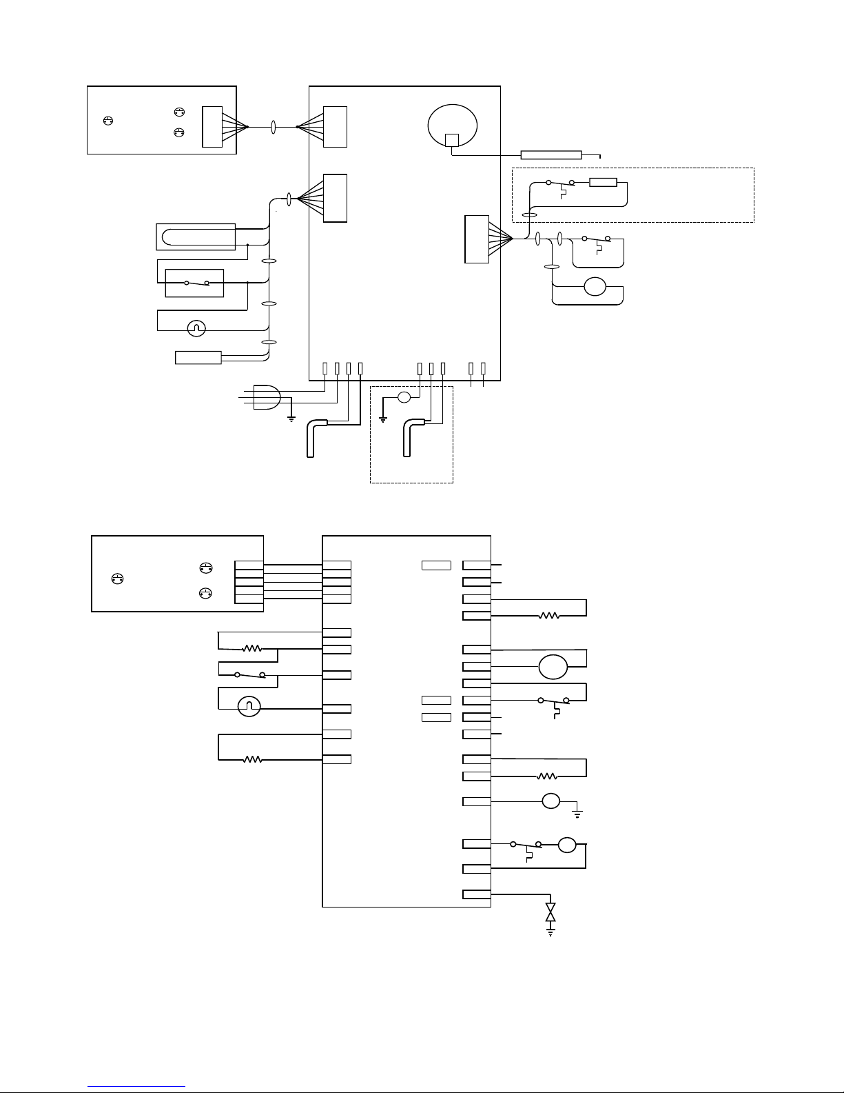
CONTROL PANEL
The refrigerator control panel is located between the
fresh food and freezer compartments of your refrigerator.
The refrigerator control requires +12 volts DC to operate.
There are three pushbuttons.
POWER ON –Pressing this pushbutton turns the
refrigerator on and off.
MODE –Pressing and holding this pushbutton cycles
the mode selections from AUTO, manual GAS, and
manual AC. Releasing the pushbutton selects the last
mode displayed. The selected mode will be displayed
for approx 5 seconds before all the mode indicators are
turned off. The active mode can be displayed at any
time by pressing and releasing the MODE pushbutton.
TEMP –Pressing and holding this pushbutton cycles the
temperature settings from 1 through 5 with 5 being the
maximum cool setting. Releasing the pushbutton
selects the last temperature setting displayed. The
selected temperature setting will be displayed for approx
5 seconds before all the temperature indicators are
turned off. The active temperature setting can be
displayed at any time by pressing and releasing the
TEMP pushbutton.
AUTO MODE
When the refrigerator is in the AUTO mode, the control
automatically selects the best energy source which is
available. When a more efficient energy source
becomes available, the refrigerator automatically
switches to the more efficient source. AC energy is
considered the more efficient energy source and is the
first choice selected by the control. Propane gas is the
second choice and is selected in the AUTO mode only
when AC energy is not available.
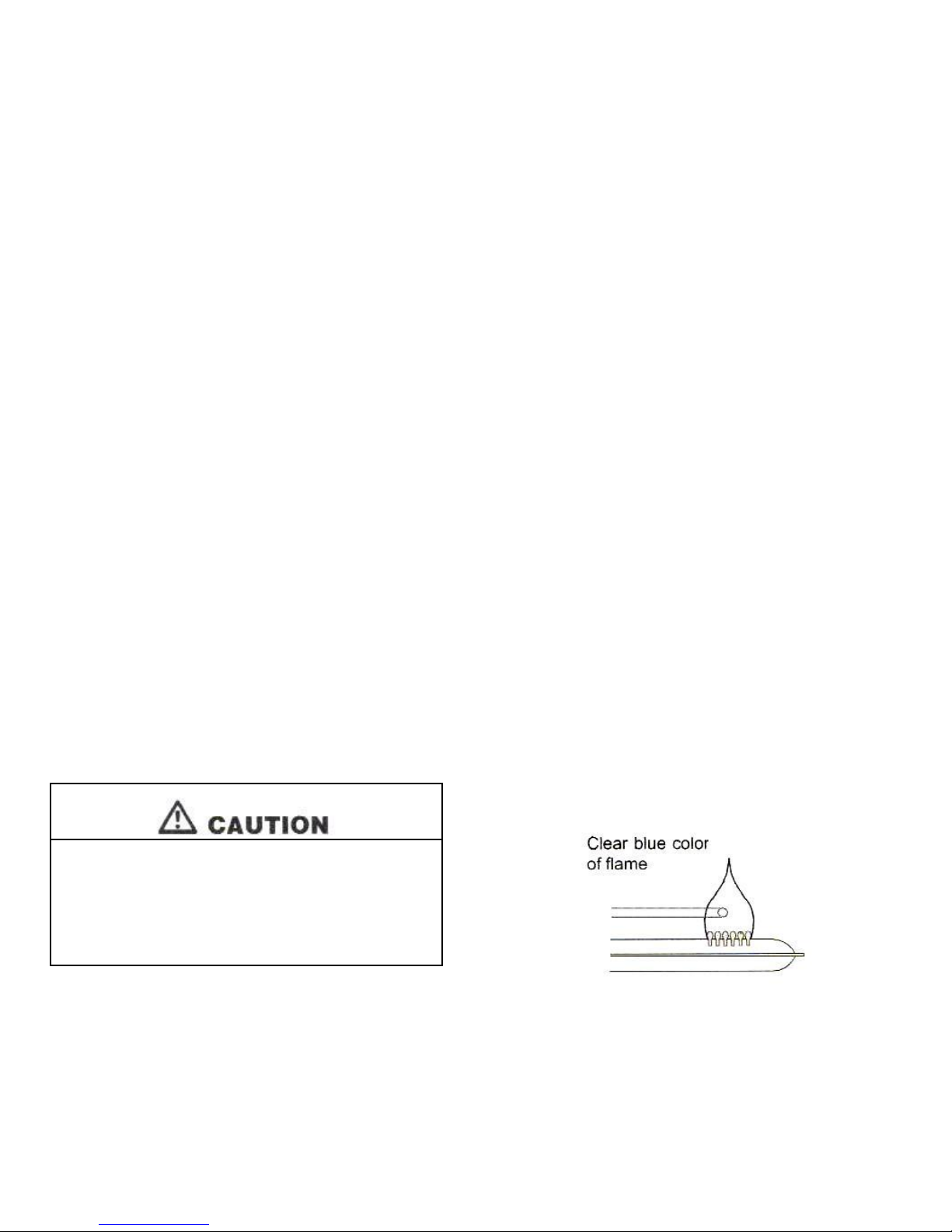
GAS MODE
The GAS mode can be selected either automatically or
manually. When switching to gas operation, the
refrigerator control begins a 40 second trial ignition
cycle. During this period, the control opens the gas
safety valve and begins sparking the burner. If after 40
seconds the control fails to detect the presence of a
flame, the control shuts off the gas safety valve and
stops sparking the burner. The CHECK indicator on the
control panel turns on indicating that the burner failed to
ignite. The CHECK indicator can be reset by turning the
refrigerator off and then back on again and a new 40
second trial ignition cycle begins. On initial start up or
after changing a propane tank, it is possible that air in
the gas supply lines will require 2 or 3 ignition trials
before successfully lighting the burner. If after repeated
attempts, the burner fails to ignite, stop and consult your
local dealer or an authorized Atwood Service Center.
MANUAL MODES
The manual modes allow for selection of either the AC or
GAS modes directly. If the selected mode’s energy
source is not available, the refrigerator is turned off, the
CHECK is turned on and the selected mode indicator flashes on
and off indicating which energy source is not available.
DOOR HANDLES
The door handles latch when closed to prevent the doors from
opening travel. When closing the doors, push each door into the
refrigerator cabinet until you hear a distinct “click” sound which
will indicate that the door is latched. To open a door, pull the
handle away from the refrigerator cabinet to unlatch the handle.
During off-season storage, the handle has a storage latch which
prevents the door from completely closing. Keeping the doors
partially opened during long term storage prevents odors from
building up in the cabinet. To engage the storage latch, open
each door about 1/2 inch, hold the door handle in the open
position, and push the storage latch into the cutout of the strike
plate. Never use the storage latch as a travel latch because the
doors will not be fully closed.
DOOR AJAR ALARM
This refrigerator has an alarm to alert you if the fresh food
compartment door is left not fully closed. If the door is left open
for more than 2 minutes, the CHECK light will be lit and a beeper
will sound a chirp approx every 5 seconds until the door is closed.
The refrigerator will continue to operate normally throughout the
door ajar alarm sequence.
MOISTURE DIVIDER HEATER
This refrigerator has a heater which is automatically controlled
and prevents moisture from forming on the center divider located
between the freezer and fresh food compartments.
BACKUP TEMPERATURE CONTROL SYSTEM
This refrigerator has a backup temperature control system which
allows the owner to have variable temperature control of the
refrigerator even if the temperature sensor should fail.
If the control cannot read the temperature sensor, the control
uses the selected temperature setting to control the refrigerator
cycle and adjust the temperature accordingly.
THERMAL SWITCH MONITOR
This refrigerator has a thermal switch which serves as an
overheating monitor.
TILT SENSOR TECHNOLOGY
This refrigerator control incorporates a patent pending tilt sensor
which enables the control to constantly monitor the angle at which
the refrigerator is operated. This feature is protects the user from
potential hazards attributed to prolonged operation at severe
angles of inclination. This monitoring function is completely
invisible to the user and only becomes apparent to the user in the
rare event that the refrigerator has been operated for prolonged
periods of time at severe tilt angles. Normal care in leveling of
your vehicle will prevent this feature from ever being noticed.